Fused Silica Microlens Arrays
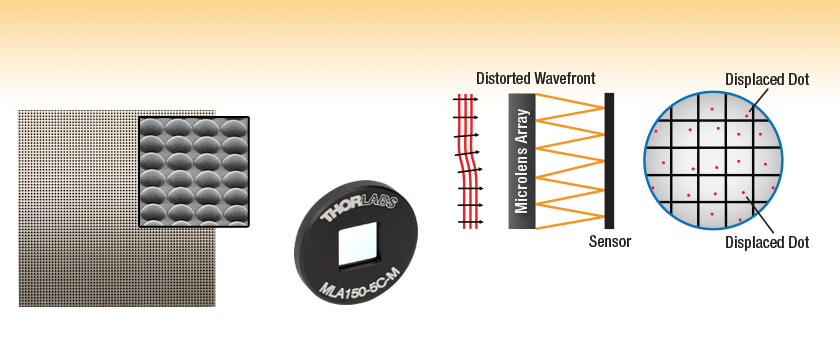
- Plano-Convex Lens Shape
- Near Diffraction-Limited Spot Sizes
- AR Coated or Chrome Masked
- Mounted and Unmounted Versions
Magnified
View
MLA150-7AR
with AR Coating
MLA150-5C-M
Mounted Lens Array
Ideally Suited for Wavefront Sensors

Please Wait
| Item # | MLA150-5C(-M) | MLA150-7AR(-M) | MLA300-14AR(-M) |
|---|---|---|---|
| Substrate Material | Fused Silica (Quartz) | ||
| Focal Length | 5.6 mm | 14.2 mm | |
| Effective (Optimal) Focal Length When Built into a Wavefront Sensor | 4.1 mm | 5.2 mm | 14.6 mm |
| Wavelength Range | 300 - 1100 nm | 400 - 900 nm | |
| Lens Type | Round, Refractive, Plano-Convex | Square, Refractive, Plano-Convex | |
| Lenslet Pitch | 150 µm | 300 µm | |
| Lens Size | Ø140 µm (Cr Mask Hole) |
Ø146 µm (Lens Diameter) |
295 µm (Square) |
| Fill Factor (Approximate)a | 68.4% | 74.4% | 96.7% |
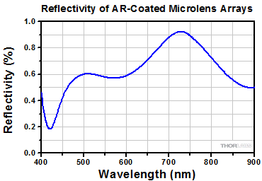
| AR Coating | No | Reflectivity <1% for 400 - 900 nm | |
| Chrome Apertures | Yes, Around Microlenses | No | |
| Reflectivity | <25%b | <1% | |
| Array Size and Type | 10 mm x 10 mm x 1.2 mm, Square Grid | ||
| Mount Window Aperture (-M Versions Only) |
9 mm x 9 mm | ||
Features
- 10 mm x 10 mm High-Quality Microlens Array
- Available Unmounted or in a Ø1" Mount
- Two Wavelength Ranges Available:
- 400 - 900 nm with an AR Coating
- 300 - 1100 nm with a Chrome Mask
- Fused Silica Substrate
- Square Grid Arrangement of Microlenses
- Arrays with 150 µm or 300 µm Lenslet Pitches Available
- Near Diffraction-Limited Spot Size
- High Spot-to-Background Contrast
- Use for Custom-Built Shack-Hartmann Wavefront Sensors
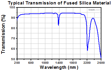
These Fused Silica Microlens Arrays are available mounted or unmounted (click here to see an enlarged photo). Fused silica offers excellent transmission characteristics from the UV to the IR. The microlenses have a plano-convex shape and are arranged in a square grid with a lens pitch of 150 µm or 300 µm. The microlens arrays with a pitch of 150 µm have round lenslets, whereas the microlens arrays with a pitch of 300 µm have square lenslets, allowing for a fill factor of 96.7%.
The MLA150-5C microlens array and its mounted counterpart have a chrome mask that blocks light from being transmitted through the spaces between microlenses, thereby increasing the contrast. The unmounted MLA150-7AR and MLA300-14AR lens arrays and their mounted versions have a broadband AR coating on both sides to reduce the surface reflections in the 400 - 900 nm spectral region to below 1%.
These lenses are formed using photolithographic techniques based on semiconductor processing technology, which allows for excellent uniformity in the shape and position of each microlens. Unlike some microlens arrays produced from molded epoxy, this method produces microlens arrays where the spot size of each microlens is nearly diffraction limited.
For the mounted versions, the microlens is glued into a Ø1", 3.5 mm thick mount plate that is compatible with all standard Ø1" optics mounts. The aperture of the lens window is 9 mm x 9 mm. Their unmounted counterparts are most easily held using one of our cylindrical lens mounts, which are specifically designed to hold square or rectangular optics.
For microlens arrays that are ideal for use in custom-built fly's eye homogenizers, please visit the PMMA Microlens Arrays page.
A microlens array used in conjunction with a CCD array can constitute the core of a Shack-Hartmann wavefront sensor. As seen in the microlens array diagrams, a planar wavefront that is transmitted through a microlens array and imaged on a CCD sensor will form a regular pattern of bright spots. If, however, the wavefront is distorted, the light imaged on the CCD sensor will consist of some regularly spaced spots mixed with displaced spots and missing spots. This information can be used to calculate the shape of the wavefront that was incident on the microlens array. Shack-Hartmann type wavefront sensors can be used to characterize the performance of optical systems. In addition, they are increasingly used in applications where real-time monitoring of the wavefront is used to control an adaptive optic with the intent of removing the wavefront distortion before creating an image.

| Posted Comments: | |
Yingwen Zhang
(posted 2025-09-28 17:13:55.877) Is the size of the MLA300-14AR customizable? The dimensions of 10x10mm is a little small for my camera, can it be made to 20x20mm? jjadvani
(posted 2025-09-29 09:55:07.0) Dear Yingwen, Thank you for contacting Thorlabs. It is possible to have a custom MLA. My colleague from your local team will contact you directly to explore this option further. Roy Maman
(posted 2024-07-04 18:38:54.21) Do you have any zemax file for this lens? if not, can you please provide CAD files?
Thanks jjadvani
(posted 2024-07-05 05:50:37.0) Dear Roy, Thank you for your feedback. I will contact you directly to discuss your requirements. Kevin Heylman
(posted 2022-11-03 12:43:29.45) Do you have data on the AR coating for the for the MLA300-14AR over a wider wavelength range? Specifically, in the NIR at 1064nm? Thanks! dpossin
(posted 2022-11-08 04:40:03.0) Dear Kevin,
Thank you for your feedback. Unfortunately we do not have extended data on the AR coating for the MLA300-14AR. user
(posted 2022-03-17 13:56:44.557) Any idea why these fused silica multi-lens arrays (e.g MLA300-14AR-M) don't work well as homogenizers, while the PMMA multi-lens arrays (eg. MLA1M1) work really well as homogenizers? The application is in generating flat top beams. wskopalik
(posted 2022-03-23 11:37:08.0) Thank you very much for your feedback!
The PMMA arrays have larger microlenses than the fused silica arrays. This makes the alignment much easier with the PMMA arrays and therefore typically leads to better homogenization results.
I will contact you directly to provide further assistance. Jinsub Kim
(posted 2021-08-25 11:29:50.93) I purchased the MLA300-14AR-M product.
1.MLA Lens sag information
2.Lens shape measurement result
can i get information about it?
Also, is there a cover glass over the lens? If yes, how thick is it? MKiess
(posted 2021-08-30 09:03:36.0) Dear Jinsub Kim , thank you very much for your inquiry. All lenslets are made from fused silica and have a plano-convex shape.
Thus, there is no protective glass over these lenses. The SAG can be calculated from the radius of curvature and the diameter of the lenses. These are given in the specification sheet of the lens array, which can be found on our website under documents of the specific item. I have contacted you directly to discuss further details. 任 骥
(posted 2021-02-19 19:51:00.14) what is the f=14.6mm? from the plano-convex surface to focal point? dpossin
(posted 2021-02-24 05:18:14.0) Dear 任 骥,
Thank you for your feedback. 14.6mm refers to the effective focal length when the MLA is mounted into the wavefrontsensor. Antonio Lorca
(posted 2020-12-11 05:07:32.46) I was wondering if it is possible to create other custom microlenses, for example a 20x20 array of microlenses with a pitch of 150 microns and a greater focal length than those provided in the catalog. soswald
(posted 2020-12-14 09:54:36.0) Dear Antonio,
thank you for your feedback. We are generally able to offer a large degree of customization for the micro lens arrays. I have contacted you directly to discuss your requirements in more detail. Minbae Kim
(posted 2020-09-21 03:08:24.523) I want to know Can I get custom MicroLens Array.
For example, Different pitch, Different Sag for Micro Lens Array. dpossin
(posted 2020-09-23 10:01:45.0) Dear Customer,
Thank you for your feedback. Basically we offer customized microlens arrays. I reach out to you to discuss your requirements. Vincenzo Vagnoni
(posted 2020-04-10 14:07:07.61) Let’s consider for example a tile of fused silica with parallel surfaces. A high energy electron impinging with normal incidence onto one face causes the emission of Cherenkov light along it’s trajectory through the fused silica, with wavelength extending to the UV region. Cherenkov photons are emitted at a fixed angle of about 45 degrees with respect to the normal, and they undergo total internal reflection when they reach the exit surface.
I’m wondering whether by applying microlenses on the exit surface it would be possible to reduce the internal reflection of such photons, such that a good fraction of them can make it through the exit surface. nreusch
(posted 2020-04-15 07:03:31.0) This is a response from Nicola at Thorlabs. Thank you for sharing your interesting experiment. Unfortunately, we do not have any experience with this kind of application ourselves, but you might find the following review helpful: B.Ratcliff, J. Va’vra, DIRC: Internally reflecting imaging Cherenkov detectors, Nuclear Instruments and Methods in Physics Research Section A: Accelerators, Spectrometers, Detectors and Associated Equipment, 2020. You preferred not to be contacted, so if you would like to deepen the discussion, please do not hesitate to contact your local Tech Support office. Congli Wang
(posted 2019-08-08 16:16:19.893) Hi,
Quick questions:
- Do parameters (lenslet height, radius) MLA150-7AR-M still the same?
- Do you still have the old document of MLA150-7AR-M (the one says lenslet height is 0.87 um)? I purchased one around Jul 26, 2018.
Thanks,
Congli MKiess
(posted 2019-08-09 10:26:34.0) This is a response from Michael at Thorlabs. Thank you very much for the inquiry. The parameters have not changed. We still offer the same MLA150-7AR Microlens Array. I have contacted you directly to provide further specifications regarding the height of the circle segment of the lens. Jeannine Knight
(posted 2019-07-03 11:43:51.037) Can you provide any information on the safe temperature range for the polymer of the microlens lens array? swick
(posted 2019-07-08 05:05:24.0) This is a response from Sebastian at Thorlabs. Thank you for the inquiry. Our Micro-Lens-Arrays do not have a polymer part, because they are made by etching fused silica. The operating temperature of mounted MLAs are limited by the epoxy used to fix the MLA to the mount. That works up to approx. 120 °C. For high-temperature applications we recommend to use the unmounted MLAs which should work up to several hundreds of °C. user
(posted 2019-04-17 10:27:03.47) Can we purchase the mounting disk only for the micro lens array ? We would like to use the mount to hold a custom made micro lens array with 10mm x 10mm in size. swick
(posted 2019-04-30 06:08:32.0) This is a response from Sebastian at Thorlabs. Thank you for the inquiry.
The mechanical mounts for MLA150-5C-M are available on request.
Please contact your local techsupport group to get an official quotation. richard.graham
(posted 2018-11-20 14:40:50.697) I am wondering if you can let me know exactly how the mounting is achieved. Specifically, I am considering an application where I will have a small amount of water in the recess of the 1" mount, sitting on top of the micro lens array. I am wondering if it is likely to leak. nreusch
(posted 2018-12-07 09:35:01.0) This is a response from Nicola at Thorlabs. Thank you very much for your inquiry! We do not use any kind of seal in the mounts, so it is indeed possible that water would leak through the mount. I will contact you directly with some additional information about how the mounts are assembled. selmantamer
(posted 2018-04-09 13:40:54.17) These micro lens arrays can be used for beam homogenization and flat top beam profile. I think thorlabs should offer other varieties of microlens arrays with different pitch sizes such as 500um or 1mm. YLohia
(posted 2018-04-09 11:53:03.0) Hello, thank you for your feedback. I will go ahead and post this product idea on our internal engineering forum. jag
(posted 2016-06-07 07:31:29.793) Dear Sirs,
do you have a reference where your microlenses array is mounted into a standard CS-mount lens? (In other words, I would like to transform a standard camera into a plenoptic camera)
Thanking in advance for any information,
Jose Gaspar besembeson
(posted 2016-06-09 02:15:19.0) Response from Bweh at Thorlabs USA. We don't provide such a reference, but we do provide the focal length of each of the microlens arrays that we carry. We have several adapters at the following page, (including C and CS adapters) that could be helpful in integrating a suitable microlens arrays to your plenoptic camera application: http://www.thorlabs.us/navigation.cfm?guide_id=2327 user
(posted 2015-04-21 15:23:00.757) Can you kindly give some information the NA of the microlenses? shallwig
(posted 2015-04-23 04:03:36.0) This is a response from Stefan at Thorlabs. Thank you very much for your inquiry. On the website in the specifications table you can find for the different micro lens models the lens diameter and the focal length. With these parameters it is possible to calculate the numerical aperture:
Tan(alpha)=D/2f => NA=sin(arctan(D/2f))
I will contact you directly to check if you need any further information. kaccie
(posted 2014-12-16 16:18:48.303) Hello Thomas,
I would like to a mechanical drawing (a 300 um pitch version) as well if possible.
Thanks shallwig
(posted 2014-12-17 10:24:25.0) This is a response from Stefan at Thorlabs. Thank you very much for your inquiry. You can find a technical drawing of the MLA300-14AR on our website in its spec sheet under the following link:
http://www.thorlabs.de/thorcat/16500/MLA300-14AR-SpecSheet.pdf
I will contact you directly to check if you need any further information and to discuss your application in detail. cohennc
(posted 2013-08-05 02:13:03.293) do yoyu have a zemax file for this?
thanks tschalk
(posted 2013-08-06 10:16:00.0) This is a response from Thomas at Thorlabs. Thank you very much for your inquiry. We don't have the zemax files for these microlens arrays but i will send you the mechanical drawings. cohennc
(posted 2013-08-05 02:10:38.687) Hi
what is the Damage threshold of this micro lens
thanks tschalk
(posted 2013-08-06 10:13:00.0) This is a response from Thomas at Thorlabs. Thank you very much for your inquiry. We do have a value for the damage threshold it is 5J/cm² for 10ns laser pulses at 1064nm. I will contact you directly with more detailed information. jvigroux
(posted 2012-08-01 05:04:00.0) A response from Julien at Thorlabs: Thank you for your feedback! The component that is best suited for holding the microlens arrays are the cylindrical lens mount:
http://www.thorlabs.com/NewGroupPage9.cfm?ObjectGroup_ID=718
I will contact you directly to discuss your exact needs and see if we can offer a customized solution that would fulfill them. b.steel1
(posted 2012-07-30 07:02:33.0) Is there a Thorlabs adaptor which can mount these? I can only find adaptors to hold circular optics. The only other mounting options I know of are V-mounts, rectangular lens mounts, or lots of glue, none of which are ideal! jvigroux
(posted 2012-07-30 06:01:00.0) A response form Julien at Thorlabs: Thank you for your question! The fill factor for the 150µm pitch is roughly 74.5%. This fill factor is related to the fact that the lenses are organized in a square matrix but that the lenses themselves are circular. The arrays having the 300µm pitch use square lenses as opposed to the 150µm ones, such that the fill factor there is 100% b.steel1
(posted 2012-07-27 17:03:21.0) Do you know the fill factor for the two pitch products? ie, What fraction of incident light remains in the focused beams/spots?
Thanks. jvigroux
(posted 2012-06-14 04:41:00.0) A response from Julien at Thorlabs: Thank you for your inquiry! We offer microlens arrays having a pitches of 150µm and 300µm in a square pattern. The linear density of microlens is thus 66 lenses/cm or 33 lenses/cm. The focal lengths that are available are 5.2mm and 6.7mm for the 150µm pitch microlens arrays and 18.6mm for the 300µm array. jaumefolch
(posted 2012-06-13 19:51:56.0) Dear Sirs, We are interested in receiving info on your microlens arrays. Two of the most important data we need to know is the concentration of the microlenses and their focal length. I look forward to receiving your feedback. With best regards, jvigroux
(posted 2011-07-11 06:33:00.0) A response form Julien at Thorlabs: we can offer other sizes, pitch and lens diameter for microlens arrays. I will contact you directly in order to discuss the exact dimensions of the arrays you need. louis.bouet
(posted 2011-07-08 06:54:13.0) I wonder if its possible to have other size for a microlense array? For example : is it possible to have a long line of lense and not a quater of 10*10mm?
Thank you for answer! Laurie
(posted 2009-04-09 11:47:24.0) Response from Laurie at Thorlabs to randall.staver: There are several ways that you can demagnify your beam, but the introduction of any optical elements into the system will introduce small distortions. That will not change the accuracy of the SH wavefront sensor measurement, but it does slightly alter the distortions being measured. To reduce the beam size by a factor of ~2, we offer beam expanders that offer magnification of 2 or 2.5 (depending on the type you choose). If you use these backwards (i.e., allow the light to enter the side with a larger diameter and exit through the side with a smaller diameter), the effect is a magnification of 1/2 or 1/2.5). You can find our line of beam expanders at this link: http://www.thorlabs.com/Navigation.cfm?Guide_ID=2023. These beam expanders use two spherical singlets to obtain the proper expansion or reduction in beam size. If you want to use an optic that would introduce less distortion you could make your own beam expander by using aspheric lenses (which are the best lenses to minimize spherical aberrations), or if you have a broadband light source, you might prefer to use achromatic lenses (which greatly reduce chromatic aberrations). randall.staver
(posted 2009-04-09 10:47:08.0) I have a technical question about using the HS sensor to measure the wavefront profile of a distortive optical element that is about 10 mm across (about twice the aperture of your shack-hartmann sensor). Is there a manner in which I can demagnify the beam onto the sensor and still preserve an accurate measurement of the wavefront? yhy
(posted 2008-08-05 10:38:41.0) I wonder if you have some mount that can hold the microlense array? |


Click to Enlarge
Figure G1.1 The fill factor is dependent upon the geometry of the microlens array in the square grid. The MLA300's square microlens array (left) yields a higher fill factor than the MLA150's round microlens array (right).
- Fused Silica Substrate
- AR Coating (MLA150-7AR and MLA300-14AR) or Chrome Mask (MLA150-5C)
- Array Size: 10 mm x 10 mm x 1.2 mm
- Square Grid Arrangement of Microlenses
- Use in Custom-Built Shack-Hartmann Wavefront Sensors*
*Please Note: Pre-assembled Shack-Hartman wavefront sensors will need to be re-calibrated if these microlenses are used in place of the microlenses already built into the system. To order additional microlens arrays for Thorlabs' Shack-Hartmann Wavefront Sensors, please contact Tech Support

- Compatible with Standard Ø1" Optic Mounts
- Lens Window Aperture: 9 mm x 9 mm
- Array Size: 10 mm x 10 mm x 1.2 mm
- Fused Silica Substrate
- AR Coating (MLA150-7AR-M and MLA300-14AR-M) or Chrome Mask (MLA150-5C-M)
- Square Grid Arrangement of Microlenses
- Use in Custom-Built Shack-Hartmann Wavefront Sensors*
*Please Note: Pre-assembled Shack-Hartman wavefront sensors will need to be re-calibrated if these microlenses are used in place of the microlenses already built into the system. To order additional microlens arrays for Thorlabs' Shack-Hartmann Wavefront Sensors, please contact Tech Support
 Products Home


 Zoom
Zoom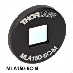
 Fused Silica Microlens Arrays