 Products Home
Quantum Optics Educational Kit
- Designed for Education, Demonstration, and Classroom Use
- Easy-to-Use Kits Include Components Plus Free Educational Materials
Shown with
B60120AX Breadboard
(Not Included)


Please Wait
Click to Enlarge
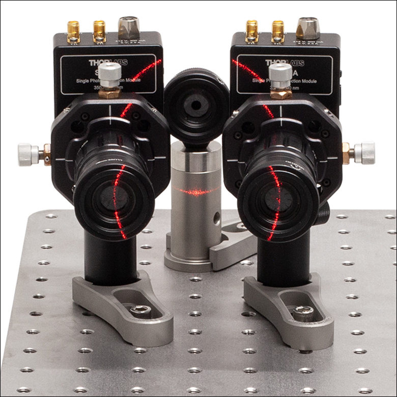
The kit contains several methods and parts that ensure a student-friendly alignment process, including an axicon. With the alignment laser, the axicon generates a light cone with the same opening angle as the photon-pairs, thus helping greatly in alignment. This image shows how the aligned detectors stand in the laser light cone.


Quantum Optics Educational Kit
- Designed for Educational, Demonstration, and Classroom Use
- Complete Photonics Kit Includes Hardware, Tools, and Software (Computer Not Included)
- Extensive Manual and Teaching Materials Provided
- Easy to Assemble and Use
- Choose from Educational Kits Containing Imperial or Metric Components
Quantum Optics Educational Kit Details
- Build a Heralded Single-Photon Source (Spontaneous Parametric Down-Conversion)
- Learn Coincidence Counting Techniques to Distinguish Classical from Non-Classical Light Sources
- Analyze the Polarization State of Single Photons
- Show How a Single Photon Interferes with Itself (Superposition of Quantum States)
- Demonstrate Particle/Wave Duality of Light in the Context of the Quantum Eraser Experiment
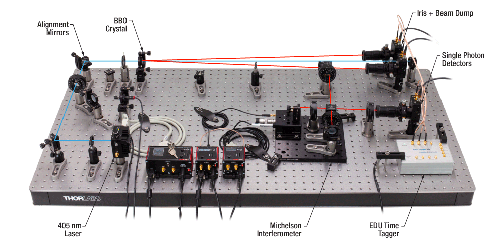
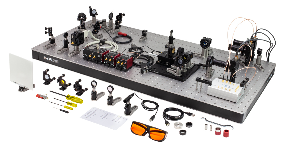
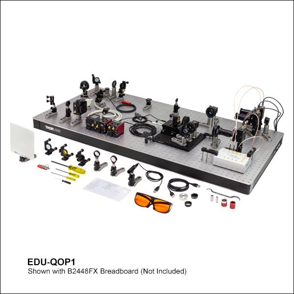
Thorlabs' EDU-QOP1(/M) Quantum Optics Educational Kit includes all the components* needed for students to investigate the quantum properties of light first-hand in an open and accessible environment. From the type-I BBO crystal used to generate photon pairs to the state-of-the-art single-photon detectors, all elements employ free-space optics to clearly show where and when the measurement occurs. Detailed step-by-step alignment instructions using an additional visible laser that mimics the single-photon emission cone ensure short setup times for each experiment. One particularly important aspect of the kit is to educate people about what constitutes a non-classical light source.
*The quantum optics kit must be mounted on an optical table or breadboard, which is not included in this kit. If your lab does not already have a suitable one, we recommend the B2448FX (B60120AX) optical breadboard with the AV5(/M) damping feet, which are available for purchase separately below.
Thorlabs Educational Products
Thorlabs' line of educational products aims to promote physics, optics, and photonics by covering many classic experiments, as well as emerging fields of research. Each educational kit includes a manual that contains both detailed setup instructions and extensive teaching materials. These lab kits are being offered at the price of the included components, with the educational materials offered for free. Technical support from our educational team is available both before and after purchase.
Purchasing Note: Both English and German language manuals are available for our educational kits. The imperial educational kit contains the English manual and US-style power cords. The appropriate manual and power cords will be included in the metric kit based on your shipping location. The power supplies and other electronic devices in both the metric and the imperial kit accept voltages of 230 VAC and 120 VAC. Please contact Tech Support if you would like the German manual included with the imperial version of the kit. As with all products on our website, taxes are not included in the price shown below.
Laser Safety
Thorlabs' Quantum Optics Educational Kit uses the L405P20 laser diode, which requires that all users be trained and follow all necessary safety protocols. This includes wearing the LG3 laser safety glasses shipped with the kit. More details about the laser classification system and Thorlabs laser safety products can be found on the Laser Safety tab.
The EDU-QOP1(/M) kit investigates the quantum properties of light, starting from the generation of (heralded) single photons and detection techniques up to experiments that demonstrate fundamental quantum mechanical concepts such as the superposition of states. Below is a brief overview of this kit; see the EDU-QOP1(/M) manual for more details.
Click to Enlarge
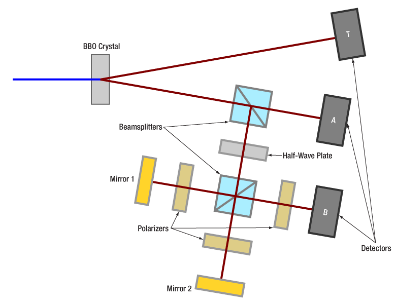
Figure 1: An overview of the kit, set up for the single photon quantum eraser experiment.
Click to Enlarge
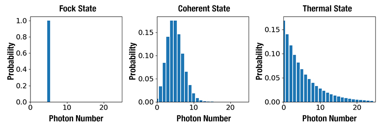
Figure 2: Photon number probabilities for a Fock state (left), a coherent state (center), and a thermal state (right), all with the same mean photon number <n> = 5.
Click to Enlarge
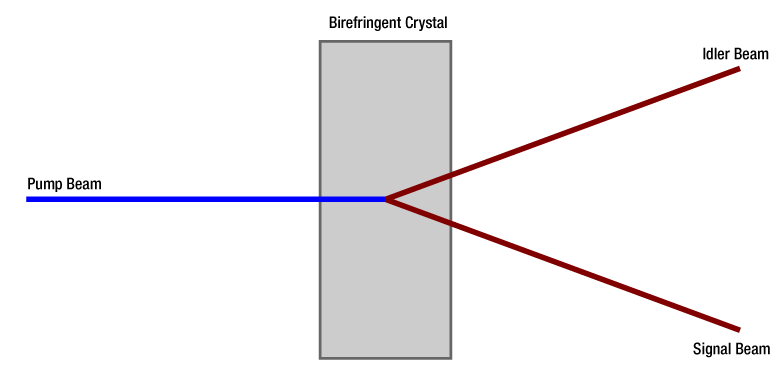
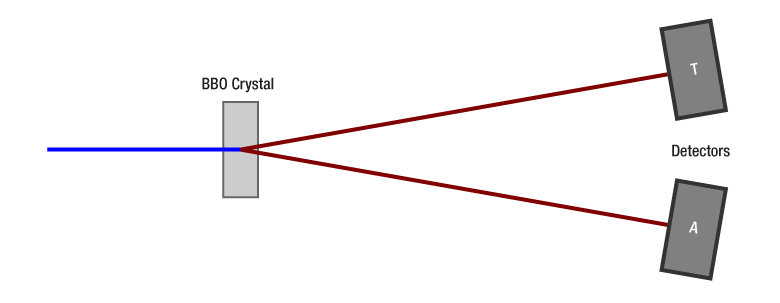
Figure 3: An idler and a signal beam are generated from a pump beam in a birefringent crystal.

Click to Enlarge
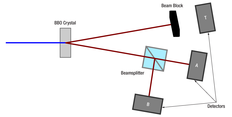
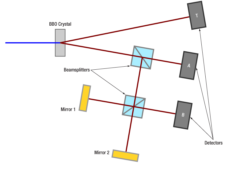
Figure 4: Measurement setup to verify operation of a heralded single photon source (Grangier-Roger-Aspect experiment). Coincidences between the three single photon detectors are analyzed.
Click to Enlarge
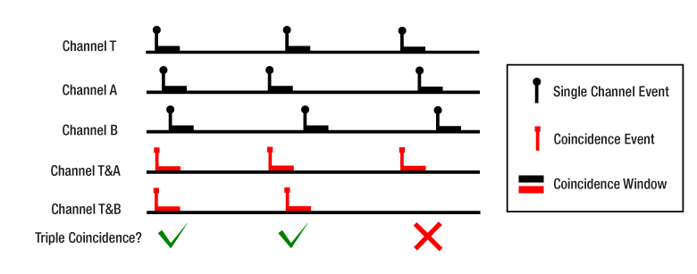
Figure 5: Definition for coincidences.
Click to Enlarge
Figure 7: How the aligned detectors stand in the laser light cone.

Click to Enlarge
Figure 6: Schematic of how light passes through an axicon.
Quantum Description of Light
In quantum mechanics, light is described by quantized excitation of the electromagnetic field, where the smallest possible excitation is a single photon (with quantum number n = 1). Fock states are non-classical light states with a well-defined photon number (see the left graph of Figure 2).
Classical light, on the other hand, does not exhibit such a well-defined photon number. For example, light generated by a laser is in a coherent state. For a given mean photon number, the actual photon number follows a Poisson distribution (see the middle graph of Figure 2). Attenuation of the laser can only reduce the mean photon number while the underlying statistic remains Poissonian. Hence, an attenuated laser can never be used as a single photon source for quantum experiments.
Other classical light sources, such as LEDs or blackbody radiation, are described by thermal states, which are mixed quantum states, and exhibit an even larger variance of in photon number compared to laser light (see the right graph of Figure 2).
Generation of Single Photons
The term “single photons” refers to Fock states with photon number n = 1. A range of different sources can be used to generate single photons. Nowadays, most experiments use a process called Spontaneous Parametric Down-Conversion (SPDC) to generate photon pairs. The EDU-QOP1(/M) kit makes use of such a source, as it is rather simple to set up and offers stable operation, which makes it ideal for lab courses.
In SPDC, pump light generates two photons inside a nonlinear crystal, as seen in Figure 3. These photons are created virtually simultaneously, so that one of the photons can be used to signal the existence of the other, making it possible to perform measurements on single photons. For this reason, such a source is also called a heralded single photon source.
The EDU-QOP1 kit uses a β-Barium borate (BBO) crystal designed for a pump wavelength of 405 nm and a degenerate pair wavelength of 810 nm. The crystal is designed for a pair opening angle of 6° for spatially separated detection of both photons.
Coincidence Detection
Three SPDMA single photon detectors are used in the kit, as seen in the schematic in Figure 4. Similar to a Geiger-Müller counter, an incoming photon creates an electron avalanche in the detector, which is detected and converted into a TTL level output signal.
These three signal channels are analyzed by an educational-grade time tagger for coincidences between the detected events, as shown in Figure 5: for each event on the Trigger channel T it checks whether there is another event on channel A or B within a few nanoseconds wide window before or after. This time period is called the coincidence window. If the condition is met, a coincidence event is generated at the coincidence channels T&A or T&B. A triple coincidence occurs if all three detectors register a photon within the coincidence window.
For a pair source, the coincidences measured between both arms occur more often than for an uncorrelated light source. This can be characterized by the second order correlation function, g(2), which compares the expected coincidences for an uncorrelated light source with the measured coincidences:

where RA and RB are the average count rates of detectors A and B, respectively, RAB is the count rate of coincidences, and Δt is the time window.
In the Grangier-Roger-Aspect experiment (see the Experiments tab), the triple coincidences are compared to the rate expected for an uncorrelated (classical) light source by using the second order correlation function g(2)GRA:

where RTAB is the triple coincidence rate, RT is the count rate of the trigger detector T, and RTA and RTB are the coincidendence rates of detectors T and A and T and B, respectively. As a single photon pair is not able to trigger events on all three detectors, the triple coincidence rate is close to zero for a heralded single photon source and thus g(2)GRA << 1.
Easy Alignment
The kit uses two iris apertures to define a common beam path for the pump and alignment lasers. For each laser, two mirrors are used for beam walking, ensuring fast and repeatable alignment of the system using visible light.
An axicon is placed at the position of the BBO crystal to generate a cone of red light from the alignment laser, which mimics the cone of photon pairs from the BBO. Using this visible indicator, the detectors can be reliably aligned at the correct positions and orientations. The laser light cone can further be used for demonstration purposes.
| Exercise | Experiment | Experiment Design | Experiment Details |
|---|---|---|---|
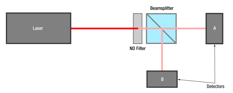
| 1 | Attenuated Laser | Experiment Description: Hanbury-Brown-Twiss (HBT) experiment with a strongly attenuated laser as light source. The light is split evenly at the beam splitter to hit both detectors A and B. The coincidence rate of both detectors is analyzed. Learning Goal: Attenuated laser light is not a single photon source. Possible Misconceptions: People tend to have the misconception that laser light is just a barrage of photons, visualized as little dots. In that image, attenuation leads to a reduction of photons, eventually just leaving “individually flying dots.” This image disregards the fact that photon arrival at a detector follows an underlying statistic. The attenuation of the laser light does not change the underlying statistic from a coherent to a non-classical source. |
|
| 2 | Pair Source | Experiment Description: A 405 nm laser hits a BBO crystal. Detectors T and A measure photons generated in the BBO by spontaneous parametric down-conversion (SPDC). The coincidences of both detectors are analyzed to characterize the light source. Learning Goal: The BBO crystal generates photon pairs. Due to their simultaneous arrival at two detectors, the coincidence counts well exceed the expected value for an arbitrary/thermal light source. Possible Misconceptions: N/A |
|
| 3 | HBT in One Arm of the Pair Source | Experiment Description: The HBT experiment (Exercise 1) is repeated within one arm of the photon pair source. Detector T is not used. Learning Goal: When only one arm of the pair source is considered, the light still shows classical characteristics. Possible Misconceptions: The misconception here is that, once the pairs are generated, we have “two single photon sources,” namely one in each arm. This is not true. When only one arm is considered, the statistics of the light are still classical. |
|
| 4 | HBT with Pair Source (GRA Experiment) | Experiment Description: The previous experiment is extended to the Grangier-Roger-Aspect (GRA) experiment by use of all three detectors. Analyzing the T&A, T&B, and triple coincidences enables characterization of the photon pair states. Learning Goal: When both photons of the pair are considered, the light in one arm shows non-classical properties. This constitutes a photon pair source, also called a heralded single photon source. Possible Misconceptions: N/A |
|
| 5 | Fluorescent Filter | Experiment Description: The previous GRA experiment is repeated with a fluorescent light source instead of the BBO pair source. Learning Goal: A measurement of light coming from a fluorescent filter similar to exercise 4 (i.e., with three detectors) does not yield a non-classical light source. Possible Misconceptions: This exercise demonstrates to students that it is really the pair source property of the light coming from the BBO that induces the non-classical nature (and not the three-detector arrangement). If a classical light source is measured in the three-detector arrangement, the properties are still classical. |
|
| 6 | Malus' Law | Experiment Description: The GRA experiment with the BBO crystal (Exercise 4) is repeated with a rotatable linear polarizer in front of detector B. The T&B coincidence rate dependence on the polarizer angle is analyzed. Learning Goal: Behavior of single photons at a polarizer. Possible Misconceptions: In classical wave theory, light that is incident on a polarizer can be split into parts that are parallel and perpendicular to the polarizer’s orientation. One is absorbed, the other transmitted. But how does this work for single photons since they cannot be split into two parts? In quantum optics, the photon’s polarization state is expressed by a superposition of base states. The proportionate transmission of a classical wave is replaced by the probability of transmitting through the polarizer. If the photon is transmitted, it retains its energy and has the polarization set by the polarizer. Otherwise, it is absorbed. |
|
| 7 | Single Photon Michelson Interferometer |
Experiment Description: A Michelson interferometer is introduced in front of detector B. The T&B coincidence rate is monitored while moving one of the interferometer mirrors. Learning Goal: Even single photons exhibit interference. Possible Misconceptions: Here, the misperception of a photon as a little flying dot is revealed: similar to a double slit, a dot-like photon would only pass through either arm of the interferometer. Thus, it would not have information about the second arm and not show interference. However, an interference behavior is observable even with a heralded single photon source. The average amount of photons in the setup is about 0.02 (even less in the Michelson interferometer part), so two photons interfering with each other can be ruled out. |
|
| 8 | Quantum Eraser | Experiment Details: Additional polarizers are introduced into both arms of the Michelson interferometer (Exercise 7). The interference signal is investigated for parallel and crossed polarizers. A third measurement is taken with a polarizer set to 45° in front of detector B. Learning Goal: Orthogonal polarizers in two interferometer arms yield path information, resulting in a loss of interference. A suitable polarizer at the output of the interferometer can erase that path information, thus recovering the interference. Possible Misconceptions: Suppose the eraser is not yet in the system. The misconception is that the photon would have to decide on one of the paths. This misconception is debunked by the fact that the polarizer at the output of the interferometer can retrieve the interference. Fundamentally, the photon is a superposition of states, and an individual state is assumed only once it is measured. If the measurement is not designed in this regard, the photon does not have to “decide” on a specific path in the interferometer. |


Learning Goals:
- Path and polarization properties of a single photon can be used to represent qubits.
- Common optical elements can be used to build quantum logic gates.
- Application Example: Understand what happens in the Deutsch algorithm from quantum mechanical and pure optical perspectives.
- Observe the importance of initial state preparation and phase noise in quantum computing applications.
In the "Additional Experiments" section of the manual, there is a detailed description of how to extend the kit to a two-qubit quantum computer that runs the Deutsch algorithm. The Deutsch algorithm is a quantum computing algorithm designed to determine whether an unknown input function, operating on one bit, is either constant or balanced. While a classical computer would need to calculate both function values f(0) and f(1) and do a comparison, the Deutsch algorithm can theoretically solve this problem in a single run.
The following additional components (not included) are required to build the algorithm based on the EDU-QOP1(/M) kit:
- Two LCC1111-B* Half-Wave LC Retarders
- Two KLC101 K-Cube Controllers
- One TPS002 Power Supply
- Two RS1.5P8E (RS1.5P4M) Ø1" (Ø25.0 mm) Pedestal Pillar Posts
- Two RS4M Ø25.0 mm Post Spacers
- Two 8-32 (M4) Setscrews, 3/4" (20 mm) Long (Packs of 50 are Available by Ordering Item # SS8S075 (SS4MS20))
- Two RSP1D(/M) Ø1" (Ø25.4 mm) Rotation Mounts
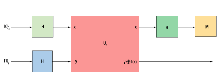
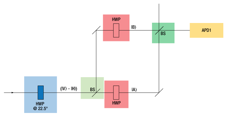
The Deutsch algorithm can be set up with half-wave plates (HWPs) and two beamsplitters (BSs) in a Mach-Zehnder interferometer configuration. In that case, there is a one-to-one correspondence between logic gates in the quantum circuitry and the optical elements. The colored logic gates in Figure 1 correspond to the color-coded elements in the optical setup in Figure 2 below. Figure 1 shows a quantum circuit that solves the Deutsch problem based on two qubits, |x> and |y>. Figure 2 describes a Mach-Zehnder interferometer configuration, where |H> and |V> are polarization states that represent the |y> qubit, and |A> and |B> are path states that represent the |x> qubit.
Click to Enlarge
Figure 1: Quantum circuit to solve the Deutsch problem, based on two qubits labeled x and y. It uses three Hadamard gates (H) and a two-qubit gate (Uf) described in the manual. The result is obtained from measuring the state of qubit x (M).
Click to Enlarge
Figure 2: Scheme for the optical implementation of the Deutsch algorithm in a Mach-Zehnder interferometer configuration. The color-highlighted elements correspond to the colored elements in Figure 1, with the result being measured at the avalanche photodiode (APD) detector.
Based on the EDU-QOP1(/M) kit, the optical implementation is set up in a Michelson interferometer configuration, due to the easier alignment and phase control of the interferometer. This means that instead of the two beamsplitters in Figure 2, only one beamsplitter is required. As the optical elements in both interferometer arms are passed twice in the Michelson configuration, the half-wave plates in the interferometer must be replaced with quarter-wave plates. Apart from that, the setup and interpretation for the Deutsch algorithm remains identical.
An example measurement is shown in Figure 3. The logic level output of the algorithm is shown, which distinguishes the two classes of functions that the Deutsch algorithm analyzes.
Click to Enlarge
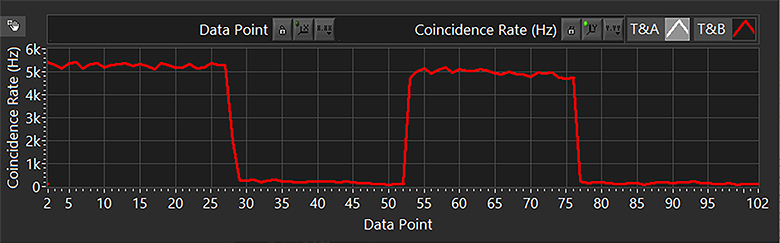
Figure 3: T&B Coincidence Signal for All Four Functions of the Deutsch Algorithm
For more details, including a more detailed theoretical description, please refer to the “Additional Experiments” chapter of the manual.
*This previous generation item is now offered as a special and can be ordered by contacting Tech Sales.
Quantum Optics Kit Components
The EDU-QOP1(/M) Quantum Optics Kit must be mounted on an optical table or breadboard. As these are common in many labs, we have not included a breadboard in this kit. If you need to purchase a breadboard separately, we recommend the B2448FX (B60120AX) optical breadboard with the AV5(/M) damping feet, which are available separately below.
Thorlabs Quantum Optics Kit is available in imperial and metric versions. In cases where the metric and imperial kits contain parts with different item numbers, metric part numbers and measurements are indicated by parentheses unless otherwise noted.
| Item # | Description | Qty. |
|---|---|---|
| Pump and Alignment Laser | ||
| LDM9T (LDM9T/M) | Laser Diode Mount with Integrated Temperature Controller | 1 |
| L405P20 | 405 nm, 20 mW, Ø5.6 mm, B Pin Code, Laser Diode | 1 |
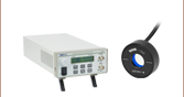
| KLD101 | K-Cube™ Laser Diode Driver | 1 |
| C230TMD-A | f = 4.51 mm, NA = 0.55, WD = 2.43 mm, Mounted Aspheric Lens, ARC: 350 - 700 nm | 1 |
| S1TM09 | SM1 to M9 x 0.5 Lens Cell Adapter | 1 |
| TPS002 | ±15 V/5 V Power Supply Unit with Mini-DIN Connectors for up to Two K- or T-Cubes | 1 |
| CAB400 | Cable for Current Controller with 9-Pin D-Sub Connector, 1.5 m | 1 |
| PL202 | Compact Laser Module with USB Connector, 635 nm, 0.9 mW (Typ.) | 1 |
| AD11NT | Ø1" Unthreaded Adapter for Ø11 mm Cylindrical Components | 1 |
| KM100CP (KM100CP/M) | Kinematic Mirror Mount for Ø1" Optics with Post-Centered Front Plate, 8-32 (M4) Taps | 1 |
| DS5 | 5 VDC, 2 A Regulated Power Supply with USB Type-A Port, 100/240 VAC | 1 |
| RS2P8E (RS2P4M) | Ø1" (25 mm) Pedestal Pillar Post, 8-32 (M4) Taps, L = 2" (50 mm) | 1 |
| RS1.5P8E (RS1.5P4M) | Ø1" (25 mm) Pedestal Pillar Post, 8-32 (M4) Taps, L = 1.5" (38 mm) | 1 |
| KB1X1 (KB25/M) | Complete 1" x 1" (25 mm x 25 mm) Kinematic Base, Top and Bottom Plates, #8 (M4) Counterbores | 1 |
| KBB1X1 (KBB25/M) | Bottom Plate Only of the KB1X1 Kinematic Base, #8 (M4) Counterbore | 1 |
| PH1E (-a) | Ø1/2" Pedestal Post Holder, Spring-Loaded Hex-Locking Thumbscrew, L = 1.19" | 1 |
| TR1 (TR30/M) | Ø1/2" (12.7 mm) Optical Post, SS, 8-32 (M4) Setscrew, 1/4"-20 (M6) Tap, L = 1" (30 mm) | 1 |
| Crystal and Adjustment Aids | ||
| - | 3 mm Thick Type-I BBO Crystal, Cutting Angle: 29.2° | 1 |
| FGL515 | Ø25 mm OG515 Colored Glass Filter, 515 nm Longpass | 1 |
| KM100CP (KM100CP/M) | Kinematic Mirror Mount for Ø1" Optics with Post-Centered Front Plate, 8-32 (M4) Taps | 2 |
| - | Kinematic Mirror Mount for Ø1" Optics with Post-Centered Front Plate, 8-32 (M4) Taps with Extra Markings | 1 |
| KB1X1 (KB25/M) | Complete 1" x 1" (25 mm x 25 mm) Kinematic Base, Top and Bottom Plates, #8 (M4) Counterbores | 1 |
| KBT1X1 (KBT25/M) | Top Plate Only of the KB1X1 Kinematic Base, #8 (M4) Counterbore | 2 |
| - | Ø1/2" Axicon, 3° Half Opening Angle of Light Cone for 635 nm | 1 |
| SM05L10 | SM05 Lens Tube, 1" Thread Depth, One Retaining Ring Included | 1 |
| SM05S5M | Ø1/2" Brass Optic Spacer, 5 mm in Length | 1 |
| SM05S10M | Ø1/2" Brass Optic Spacer, 10 mm in Length | 1 |
| AD1T | Ø1" OD Adapter for Ø1/2" Optic, Internally SM05 Threaded, 0.23" Thick | 1 |
| PH1E (-a) | Ø1/2" (12.7 mm) Pedestal Post Holder, Spring-Loaded Hex-Locking Thumbscrew, L = 1.19" (30.1 mm) | 1 |
| TR1 (TR30/M) | Ø1/2" (12.7 mm) Optical Post, SS, 8-32 (M4) Setscrew, 1/4"-20 (M6) Tap, L = 1" (30 mm) | 1 |
| Optics | ||
| PF10-03-F01 | Ø1" UV-Enhanced Aluminum Mirror | 4 |
| KM100 | Kinematic Mirror Mount for Ø1" Optics | 4 |
| KCP1 (KCP1/M) | Centering Plate for Kinematic Mirror Mount for Ø1" Optic | 4 |
| RS2P8E (RS2P4M) | Ø1" (25 mm) Pedestal Pillar Post, 8-32 (M4) Taps, L = 2" (50 mm) | 5 |
| RS1.5P8E (RS1.5P4M) | Ø1" (25 mm) Pedestal Pillar Post, 8-32 (M4) Taps, L = 1.5" (38 mm) | 1 |
| KB1X1 (KB25/M) | Complete 1" x 1" (25 mm x 25 mm) Kinematic Base, Top and Bottom Plates, #8 (M4) Counterbores | 1 |
| CCM5-BS017 (CCM5-BS017/M) |
16 mm Cage Cube-Mounted Non-Polarizing Beamsplitter, 700 - 1100 nm, 8-32 (M4) Tap | 1 |
| RS2.5P (RS2.5P/M) | Ø1" (25 mm) Pedestal Pillar Post, 1/4"-20 (m6) Taps, L = 2.5" (65 mm) | 1 |
| -b | Post-Mountable Iris, Ø15.0 mm Max Aperture, 8-32 (M4) Threaded Stud | 1 |
| -c | Post-Mountable Iris, Ø25.0 mm Max Aperture, 3/4" (20 mm) Long 8-32 (M4) Setscrew | 1 |
| RSP1D (RSP1D/M) | Rotation Mount for Ø1" (Ø25.4 mm) Optics with Adjustable Zero, 8-32 (M4) Tap | 1 |
| WPH10ME-405 | Ø1" Mounted Polymer Zero-Order Half-Wave Plate, SM1-Threaded Mount, 405 nm | 1 |
| LMR1 (LMR1/M) | Lens Mount with Retaining Ring for Ø1" Optics, 8-32 (M4) Tap | 1 |
| VRC4D1 | Ø1" Alignment Disk, S,C, & L Bands (790 - 840, 870 - 1070, 1500 - 1590 nm) | 1 |
| EDU-VS1 (EDU-VS1/M) |
Post-Mountable White Polystyrene Viewing Screen, 5.91" x 5.91 (150 mm x 150 mm) | 1 |
| SMR1 (SMR1/M) | Ø1" Lens Mount with SM1 Internal Threads and No Retaining Lip, 8-32 (M4) Tap | 1 |
| SM1D12D | SM1 Ring-Actuated Iris Diaphragm (Ø0.8 - Ø12.0 mm) | 2 |
| SM1CP2 | Externally SM1-Threaded End Cap | 1 |
| SM05CP2 | Externally SM05-Threaded End Cap | 1 |
| PH2E (PH50E/M) | Ø1/2" (12.7 mm) Pedestal Post Holder, Spring-Loaded Hex-Locking Thumbscrew, L = 2.19" (54.7 mm) | 1 |
| TR2 (TR50/M) | Ø1/2" (12.7 mm) Optical Post, SS, 8-32 Setscrew, 1/4"-20 Tap, L = 2" (50 mm) | 1 |
| PH1.5E (PH40E/M) | Ø1/2" (12.7 mm) Pedestal Post Holder, Spring-Loaded Hex-Locking Thumbscrew, L = 1.69" (44.7 mm) | 1 |
| TR1.5 (TR40/M) | Ø1/2" (12.7 mm) Optical Post, SS, 8-32 Setscrew, 1/4"-20 Tap, L = 1.5" (40 mm) | 2 |
| PH1E (PH30E/M) | Ø1/2" (12.7 mm) Pedestal Post Holder, Spring-Loaded Hex-Locking Thumbscrew, L = 1.19" (34.7 mm) | 1 |
| PH082E (PH20E/M) | Ø1/2" (12.7 mm) Pedestal Post Holder, Spring-Loaded Hex-Locking Thumbscrew, L = 1" (25 mm) | 1 |
| TR075 (TR20/M) | Ø1/2" (12.7 mm) Optical Post, SS, 8-32 Setscrew, 1/4"-20 Tap, L = 0.75" (20 mm) | 1 |
| RS4M (RS5M) | Ø25.0 mm Post Spacer, Thickness = 4 mm (5 mm) | 1 |
| RS10M | Ø25.0 mm Post Spacer, Thickness = 10 mm | 2 |
| RS3M (RS1M) | Ø25.0 mm Post Spacer, Thickness = 3 mm (1 mm) | 1 |
| RS06M | Ø24.5 mm Post Spacer, Thickness = 0.6 mm | 1 |
| AP8E25E (AP6M4M) | Adapter with External 8-32 (M4 x 0.7) Threads and External 1/4"-20 (M6 x 1.0) Threads | 1 |
| SM1L03 | SM1 Lens Tube, 0.30" Thread Depth, One Retaining Ring Included | 1 |
| EBP1 | Economy 30:70 Beamsplitter, Ø1", AOI: 45° | 1 |
| NE30A | Ø25 mm Absorptive ND Filter, SM1-Threaded Mount, Optical Density: 3.0 | 1 |
| SM1A1 | Adapter with External SM05 Threads and Internal SM1 Threads | 1 |
| Item # | Description | Qty. |
|---|---|---|
| Detectors | ||
| SPDMA | Single Photon Detection Module, 350 - 1100 nm, Ø500 µm Active Area | 3 |
| CXY1A | 30 mm Cage System, XY Translating Lens Mount for Ø1" Optics | 3 |
| SM1NR05 | SM1 Zoom Housing for Ø1/2" Optics | 3 |
| AC127-050-B | f = 50.0 mm, Ø1/2" Achromatic Doublet, ARC: 650 - 1050 nm | 3 |
| - | Ø1" Bandpass Filter, CWL = 810 ± 2 nm, FWHM = 10 ± 1 nm | 3 |
| SM1D12D | SM1 Ring-Actuated Iris Diaphragm (Ø0.8 - Ø12.0 mm) | 3 |
| SM1L05 | SM1 Lens Tube, 0.50" Thread Depth, One Retaining Ring Included | 3 |
| - | Dovetail Adapter | 3 |
| DTSM1 | External SM1 Threads to Female D4T Dovetail Adapter | 3 |
| SM1NT1 | SM1 (1.035"-40) Locking Ring, 1.25" Outer Diameter, Slots for Spanner Wrench | 3 |
| PH2E (PH50E/M) | Ø1/2" (12.7 mm) Pedestal Post Holder, Spring-Loaded Hex-Locking Thumbscrew, L = 2.19" (54.7 mm) | 3 |
| TR2 (TR50/M) | Ø1/2" (12.7 mm) Optical Post, SS, 8-32 Setscrew, 1/4"-20 Tap, L = 2" (50 mm) | 3 |
| AP8E4M (Metric Kit Only) |
Adapter with External 8-32 Threads and External M4 x 0.7 Threads | 3 |
| Michelson Interferometer | ||
| MB8 (MB2020/M) | Aluminum Breadboard 8" x 8" x 1/2" (200 mm x 200 mm x 12.7 mm), 1/4"-20 (M6) Taps | 1 |
| NFL5DP20S (NFL5DP20S/M) | NanoFlex™ 5 mm Travel Translation Stage with Diff. Drive and Closed-Loop 20 µm Piezo Actuator | 1 |
| NFL5P1 (NFL5P1/M) | NanoFlex™ NFL5D Series Base Plate | 1 |
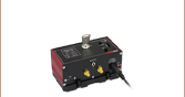
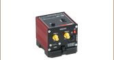
| KPZ101 | K-Cube Piezo Controller | 1 |
| KSG101 | K-Cube Strain Gauge Reader | 1 |
| TPS002 | 15 V/5 V Power Supply Unit with Mini-DIN Connectors for up to Two K- or T-Cubes | 1 |
| PF10-03-M01 | Ø1" Protected Gold Mirror | 2 |
| KM100 | Kinematic Mirror Mount for Ø1" Optics | 2 |
| KCP05 (KCP05/M) | Centering Plate for Kinematic Mirror Mount for Ø1/2" Optic | 1 |
| RS1.5P8E (RS1.5P4M) | Ø1" (25 mm) Pedestal Pillar Post, 8-32 (M4) Taps, L = 1.5" (38 mm) | 1 |
| RS6M | Ø25.0 mm Post Spacer, Thickness = 6 mm | 1 |
| CCM5-BS017 (CCM5-BS017/M) |
16 mm Cage Cube-Mounted Non-Polarizing Beamsplitter, 700 - 1100 nm, 8-32 (M4) Tap | 1 |
| RS2P (RS2P/M) | Ø1" (25.0 mm) Pedestal Pillar Post, 1/4"-20 Taps, L = 2" (50 mm) | 1 |
| AP8E25E (AP6M4M) | Adapter with External 8-32 (M4 x 0.7) Threads and External 1/4"-20 (M6 x 1.0) Threads | 1 |
| RS3M | Ø25.0 mm Post Spacer, Thickness = 3 mm | 1 |
| LEDMT1F | USB-Powered LED Mount, 62 Ω Resistor | 1 |
| LED660L | 660 nm LED with a Glass Lens, 13 mW, TO-18 | 2 |
| SMR05 (SMR05/M) | Ø1/2" Lens Mount with SM05 Internal Threads and No Retaining Lip, 8-32 (M4) Tap | 1 |
| SM05L10 | SM05 Lens Tube, 1" Thread Depth, One Retaining Ring Included | 1 |
| USB-C-72 | 72" USB 2.0 Type-A High Speed Extension Cable, Black | 1 |
| LMR1 (LMR1/M) | Lens Mount with Retaining Ring for Ø1" Optics, 8-32 (M4) Tap | 1 |
| LB1471 | N-BK7 Bi-Convex Lens, Ø1", f = 50.0 mm, Uncoated | 1 |
| -a | Post-Mountable Iris, Ø8.0 mm Max Aperture, 8-32 (M4) Threaded Stud | 1 |
| PH2E (PH50E/M) | Ø1/2" (12.7 mm) Pedestal Post Holder, Spring-Loaded Hex-Locking Thumbscrew, L = 2.19" (54.7 mm) | 2 |
| TR2 (TR50/M) | Ø1/2" (12.7 mm) Optical Post, SS, 8-32 Setscrew, 1/4"-20 Tap, L = 2" (50 mm) | 2 |
| PH1.5E (PH40E/M) | Ø1/2" (12.7 mm) Pedestal Post Holder, Spring-Loaded Hex-Locking Thumbscrew, L = 1.69" (44.7 mm) | 1 |
| TR1.5 (TR40/M) | Ø1/2" (12.7 mm) Optical Post, SS, 8-32 Setscrew, 1/4"-20 Tap, L = 1.5" (40 mm) | 1 |
| CA2912 | SMA Coaxial Cable, SMA Male to SMA Male, 12" (304 mm) | 1 |
| Time Tagger and Software | ||
| - | EDU Kit Time Tagger | 1 |
| CA2924 | SMA Coaxial Cable, SMA Male to SMA Male, 24" (609 mm) | 3 |
| - | USB Stick w/ EDU-QOP1 Software Package | 1 |
| Quantum Eraser | ||
| LPNIRB050 | Ø1/2" Unmounted Linear Polarizer, 650 - 1100 nm | 2 |
| LPNIRE100-B | Ø1" Linear Polarizer with N-BK7 Windows, 600 - 1100 nm | 1 |
| WPH10ME-808 | Ø1" Mounted Polymer Zero-Order Half-Wave Plate, SM1-Threaded Mount, 808 nm | 1 |
| RSP1D (RSP1D/M) | Rotation Mount for Ø1" (Ø25.4 mm) Optics with Adjustable Zero, 8-32 (M4) Tap | 4 |
| SM1A6T | Adapter with External SM1 Threads and Internal SM05 Threads, 0.40" Long | 2 |
| RS1.5P8E (RS1.5P4M) | Ø1" (25 mm) Pedestal Pillar Post, 8-32 (M4) Taps, L = 1.5" (38 mm) | 2 |
| RS2P8E (RS2P4M) | Ø1" (25 mm) Pedestal Pillar Post, 8-32 (M4) Taps, L = 2" (50 mm) | 2 |
| RS4M (RS5M) | Ø25.0 mm Post Spacer, Thickness = 4 mm (5 mm) | 2 |
| RS4M | Ø25.0 mm Post Spacer, Thickness = 4 mm | 2 |
| PS3 | Mounting Post Spacer, Height = 1/2" | 1 |
| Mounting and Tools | ||
| CF125-P5 | Clamping Fork, 1.24" Counterbored Slot, Universal, 5 Pack | 5 |
| - | Clamping Fork, 0.40" Counterbored Slot, Universal | 2 |
| CL2 (CL2/M) | Heavy-Duty Variable Height Clamp, 1/4"-20 (M6) Tapped | 2 |
| CL5A | Table Clamp, L-Shape, Rounded Lip | 2 |
| SPW606 | Spanner Wrench for SM1-Threaded Retaining Rings, Length = 1.00" | 1 |
| SPW909 | Spanner Wrench for SM1-Threaded Adapters, Length = 1" | 1 |
| SPW603 | Spanner Wrench for SM05-Threaded Retaining Rings, Length = 1.00" | 1 |
| SPW301 | Spanner Wrench for an M9 x 0.5 Optics Housing | 1 |
| SPW502 | Spanner Wrench for Slotted SM05, SM1, and C-Mount Locking Rings | 1 |
| CS1 | Screw-On Cable Straps (Qty. 15) | 1 |
| LG3 | Laser Safety Glasses, Light Orange Lenses, 48% Visible Light Transmission, Universal Style | 1 |
| - | Label Sheet | 1 |
Imperial Kit: Included Hardware and Screws
| Item # | Description | Qty. | Item # | Description | Qty. |
|---|---|---|---|---|---|
| Screws and Washers | |||||
| SH8S025a | 8-32 Cap Screw, 1/4" Long |
14 | SH25S025b | 1/4"-20 Cap Screw, 1/4" Long |
14 |
| SH8S0625a | 8-32 Cap Screw, 5/8" Long |
1 | SH25S038b | 1/4"-20 Cap Screw, 3/8" Long |
37 |
| SS8S050a | 8-32 Setscrew, 1/2" Long |
2 | SH25S100b | 1/4"-20 Cap Screw, 1" Long |
2 |
| SS8S0625a | 8-32 Setscrew, 5/8" Long |
1 | SH25S200b | 1/4"-20 Cap Screw, 2" Long |
2 |
| SS8S075a | 8-32 Setscrew, 3/4" Long |
6 | - | 1/4"-20 Cap Screw, 2.5" Long |
2 |
| - | W25S050c | 1/4" Washer | 100 | ||
| Hex Keys, Ball Drivers, and Screwdriver | |||||
| BD-5/64 | 5/64" Balldriver | 1 | - | 0.050" Hex Key | 1 |
| BD-9/64 | 9/64" Balldriver | 1 | - | 1/16" Hex Key | 1 |
| BD-3/16 | 3/16" Balldriver | 1 | - | 1.8 mm x 0.5 mm Slit Screwdriver |
1 |
Metric Kit: Included Hardware and Screws
| Item # | Description | Qty. | Item # | Description | Qty. |
|---|---|---|---|---|---|
| Screws and Washers | |||||
| SH4MS06a | M4 Cap Screw, 6 mm Long |
14 | SH6MS06b | M6 Cap Screw, 6 mm Long |
14 |
| SH4MS16a | M4 Cap Screw, 16 mm Long |
1 | SH6MS10b | M6 Cap Screw, 10 mm Long |
37 |
| SS4MS12a | M4 Setscrew, 12 mm Long |
2 | SH6MS25b | M6 Cap Screw, 25 mm Long |
2 |
| SS4MS16a | M4 Setscrew, 16 mm Long |
1 | SH6MS50b | M6 Cap Screw, 50 mm Long |
2 |
| SS4MS20a | M4 Setscrew, 20 mm Long |
6 | - | M6 Cap Screw, 65 mm Long |
2 |
| - | W25S050c | M6 Washer | 100 | ||
| Hex Keys, Ball Drivers, and Screwdriver | |||||
| BD-2M | 2 mm Balldriver | 1 | - | 1.3 mm Hex Key | 1 |
| BD-3M | 3 mm Balldriver | 1 | - | 1.5 mm Hex Key | 1 |
| BD-5M | 5 mm Balldriver | 1 | - | 1.8 mm x 0.5 mm Slit Screwdriver |
1 |
| Recommended System Requirements | |
|---|---|
| Operating System | Windows® 10 and Higher (64-Bit) |
| Interface | Four Free USB 2.0 Ports (Or Suitable USB Hub) |
Software
Each kit includes a USB Stick with the free EDU-QOP1 software package, which is used to set the acquisition parameters and record the measurements. A computer running Windows® 10 or higher is required, as well as four USB 2.0 ports (or a suitable USB hub) for connecting the coincidence counter and K-Cube controllers (included with the kit). Measurements can be saved as .csv files and measurement parameters are saved as a .xml file.
The software requires an installation of Kinesis® and Swabian Instruments Time Tagger software packages (all installers included on the USB stick). The software is written in LabVIEW and built as a Windows-executable file. Please contact Tech Support for a copy of our LabVIEW code if you plan to expand upon our experiment.
Kinesis Software
Version 1.14.47
The Kinesis Software Package, which includes a GUI for control of Thorlabs' Kinesis and APT™ system controllers.
Also Available:
- Communications Protocol
EDU-QOP1 Software
Version 1.0.0.15
The EDU-QOP1(/M) Software includes a GUI for monitoring the detector signals during alignment, setting measurement parameters, and acquiring the coincidence counts.

Click to Enlarge
Figure 1: Alignment Tab of Software
Alignment Tab
This tab, which is shown in Figure 1, is used to align the setup before taking measurements. The count rates of the three detectors T, A, and B are shown in the upper graph, while the lower graph can be selected to either show the coincidence count rates between T&A and T&B, respectively, or the second order correlation g(2)(0) for these detector pairs. Count rates are measured over intervals of 0.5 s and both graphs are updated at the corresponding rate (twice per second).

Click to Enlarge
Figure 2: GRA Tab of Software
HBT/GRA Tab
In these tabs the Hanbury-Brown-Twiss experiment and the Grangier-Roger-Aspect experiment can be performed. Both tabs have a similar structure, only differing in the shown quantities.
The g(2)(0) values calculated by the software are displayed together with all raw data that is required for statistical error analysis. The graph below plots the g(2)(0) value over time, making it possible to see how the correlation function stabilizes with increasing measurement duration.

Click to Enlarge
Figure 3: Malus' Law Tab of Software
Malus Tab
This tab is used for the measurement of Malus’ law for single photons. In this tab, you can perform several Grangier-Roger-Aspect-like measurements for different angles of a polarizer in front of detector B and add those data points to the two plots on the right side of the tab. The collected results can then be saved in a single file.
The upper plot shows the T&B coincidence count rates, which are the detected heralded single-photon events. The lower plot shows the g(2)(0) values calculated from the count rates and is used to verify the non-classical properties of the light source for all of the above measurements.

Click to Enlarge
Figure 4: Michelson Interferometer Tab of Software
Michelson Tab
In this tab, the single-photon interference experiments as well as the quantum eraser experiment can be performed.
The graphs show the coincidence count rate of detectors T&B (upper graph) and the correlation g(2)(0) (lower graph) as a function of the stage position of the Michelson interferometer.
Video Tutorials
In addition to the step-by-step alignment guides in the manual that are tailored to the kit, we recommend the following Video Insights. This selection covers tips and tricks about alignment skills which are useful when setting up the kit.
This Video Insight demonstrates two methods for aligning a laser beam so that it propagates parallel to the surface of the optical table.
This Video Insight demonstrates how to install a TO can laser diode in a mount and set it up to run under temperature and current control; it also includes tips for keeping humans and laser diodes safe from harm.
This Video Insight shines a spotlight on common building-block optomechanical components (such as posts, post holders, and bases) and includes tips learned though long experience designing and working with them.
This Video Insight demonstrates a procedure for optically aligning the axis of a polarizer to be perpendicular to the optical table.
Thorlabs' Quantum Optics Educational Kit uses the L405P20 laser diode, which requires that all users be trained and follow all necessary safety protocols. This includes wearing the LG3 laser safety glasses shipped with the kit. More details about the laser classification system and Thorlabs laser safety products can be found on the Laser Safety tab.
Laser Safety and Classification
Safe practices and proper usage of safety equipment should be taken into consideration when operating lasers. The eye is susceptible to injury, even from very low levels of laser light. Thorlabs offers a range of laser safety accessories that can be used to reduce the risk of accidents or injuries. Laser emission in the visible and near infrared spectral ranges has the greatest potential for retinal injury, as the cornea and lens are transparent to those wavelengths, and the lens can focus the laser energy onto the retina.
 |
 |
 |
 |
 |
 |
 |
 |
 |
Safe Practices and Light Safety Accessories
- Laser safety eyewear must be worn whenever working with Class 3 or 4 lasers.
- Regardless of laser class, Thorlabs recommends the use of laser safety eyewear whenever working with laser beams with non-negligible powers, since metallic tools such as screwdrivers can accidentally redirect a beam.
- Laser goggles designed for specific wavelengths should be clearly available near laser setups to protect the wearer from unintentional laser reflections.
- Goggles are marked with the wavelength range over which protection is afforded and the minimum optical density within that range.
- Laser Safety Curtains and Laser Safety Fabric shield other parts of the lab from high energy lasers.
- Blackout Materials can prevent direct or reflected light from leaving the experimental setup area.
- Thorlabs' Enclosure Systems can be used to contain optical setups to isolate or minimize laser hazards.
- A fiber-pigtailed laser should always be turned off before connecting it to or disconnecting it from another fiber, especially when the laser is at power levels above 10 mW.
- All beams should be terminated at the edge of the table, and laboratory doors should be closed whenever a laser is in use.
- Do not place laser beams at eye level.
- Carry out experiments on an optical table such that all laser beams travel horizontally.
- Remove unnecessary reflective items such as reflective jewelry (e.g., rings, watches, etc.) while working near the beam path.
- Be aware that lenses and other optical devices may reflect a portion of the incident beam from the front or rear surface.
- Operate a laser at the minimum power necessary for any operation.
- If possible, reduce the output power of a laser during alignment procedures.
- Use beam shutters and filters to reduce the beam power.
- Post appropriate warning signs or labels near laser setups or rooms.
- Use a laser sign with a lightbox if operating Class 3R or 4 lasers (i.e., lasers requiring the use of a safety interlock).
- Do not use Laser Viewing Cards in place of a proper Beam Trap.
Laser Classification
Lasers are categorized into different classes according to their ability to cause eye and other damage. The International Electrotechnical Commission (IEC) is a global organization that prepares and publishes international standards for all electrical, electronic, and related technologies. The IEC document 60825-1 outlines the safety of laser products. A description of each class of laser is given below:
| Class | Description | Warning Label |
|---|---|---|
| 1 | This class of laser is safe under all conditions of normal use, including use with optical instruments for intrabeam viewing. Lasers in this class do not emit radiation at levels that may cause injury during normal operation, and therefore the maximum permissible exposure (MPE) cannot be exceeded. Class 1 lasers can also include enclosed, high-power lasers where exposure to the radiation is not possible without opening or shutting down the laser. |  |
| 1M | Class 1M lasers are safe except when used in conjunction with optical components such as telescopes and microscopes. Lasers belonging to this class emit large-diameter or divergent beams, and the MPE cannot normally be exceeded unless focusing or imaging optics are used to narrow the beam. However, if the beam is refocused, the hazard may be increased and the class may be changed accordingly. | 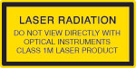 |
| 2 | Class 2 lasers, which are limited to 1 mW of visible continuous-wave radiation, are safe because the blink reflex will limit the exposure in the eye to 0.25 seconds. This category only applies to visible radiation (400 - 700 nm). | 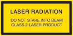 |
| 2M | Because of the blink reflex, this class of laser is classified as safe as long as the beam is not viewed through optical instruments. This laser class also applies to larger-diameter or diverging laser beams. | 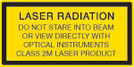 |
| 3R | Class 3R lasers produce visible and invisible light that is hazardous under direct and specular-reflection viewing conditions. Eye injuries may occur if you directly view the beam, especially when using optical instruments. Lasers in this class are considered safe as long as they are handled with restricted beam viewing. The MPE can be exceeded with this class of laser; however, this presents a low risk level to injury. Visible, continuous-wave lasers in this class are limited to 5 mW of output power. | 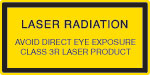 |
| 3B | Class 3B lasers are hazardous to the eye if exposed directly. Diffuse reflections are usually not harmful, but may be when using higher-power Class 3B lasers. Safe handling of devices in this class includes wearing protective eyewear where direct viewing of the laser beam may occur. Lasers of this class must be equipped with a key switch and a safety interlock; moreover, laser safety signs should be used, such that the laser cannot be used without the safety light turning on. Laser products with power output near the upper range of Class 3B may also cause skin burns. | 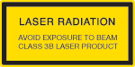 |
| 4 | This class of laser may cause damage to the skin, and also to the eye, even from the viewing of diffuse reflections. These hazards may also apply to indirect or non-specular reflections of the beam, even from apparently matte surfaces. Great care must be taken when handling these lasers. They also represent a fire risk, because they may ignite combustible material. Class 4 lasers must be equipped with a key switch and a safety interlock. |  |
| All class 2 lasers (and higher) must display, in addition to the corresponding sign above, this triangular warning sign. |  |
|

Dr. Rüdiger Scholz

Dr. Kim-Alessandro Weber
We are grateful for the various insights we have collected over the years from numerous committed educators who have taken on the challenge of experimentally teaching quantum optics to students.
The experimental realization in this kit was heavily influenced by our collaborators from the Leibniz University Hannover. We cordially thank Dr. Kim-Alessandro Weber and Dr. Rüdiger Scholz for their outstanding contributions to this kit. Between them, they have more than 40 years of experience in designing quantum optics and photon statistics experiments. This kit’s design borrows many ideas from the experiments they set up to teach both college students as well as teachers and students from high schools. We are grateful for their enthusiasm to share this experience with the rest of the teaching community by means of this kit. Finally, we thank them for testing and providing extensive feedback on the SPDMA single-photon detector incorporated into this kit during its development.
We cordially thank Paul Schlummer, Adrian Abazi, Carsten Schuck, and Wolfram Pernice from the University of Münster for supporting the development of this educational quantum optics setup. We acknowledge countless fruitful discussions, both on the physical as well as the teaching aspects of quantum systems. In particular, we are grateful for the thorough comparison to a type-II BBO system and their detailed feedback on our SPDMA single photon detector.
We also gratefully acknowledge the contributions of Prof. Dr. Jan-Peter Meyn who was one of the early adopters of real quantum optics experiments in the German teaching community (e.g., P. Bronner et al 2009 Eur. J. Phys. 30 1189). His expertise and the optical design of his setups helped spread knowledge among educators and was also an inspiration to certain design elements in the setups from Dr. Kim-Alessandro Weber and Dr. Rüdiger Scholz.
Do you have ideas for an experiment that you would like to see implemented in an educational kit? Contact us at techsupport@thorlabs.com; we'd love to hear from you.
| Posted Comments: | |
user
(posted 2024-01-29 20:46:40.44) On installing the software I am getting an error:
LabVIEW: (Hex 0x3EB) The VI is not executable. This error may occur because the VI is either broken or contains a subVI that LabVIEW cannot locate. Select File>>Open to open the VI and verify that you can run it.
Couldn't find any .vi files in the folder. How to solve this error? Jow-Tsong Shy
(posted 2023-08-15 10:57:38.697) 1. What is the average time for a undergraduate student to carry out all lab experiments?
2. Please send us a quote for two sets.
Thanks. fmortaheb
(posted 2023-08-16 10:52:58.0) Thank you very much for contacting Thorlabs and your interest in our products. We will reach out to you directly to discuss your inquiry. |

 Zoom
Zoom- Includes Components to Investigate Quantum Properties of Light (Computer Not Included)
- Requires a User-Supplied Optical Table or Breadboard with Damping Feet
- Recommended Optical Breadboard and Damping Feet Sold Below
- Free-Space Optics to Show Where and When Measurement Occurs
Thorlabs' EDU-QOP1(/M) Quantum Optics Educational Kit includes components to investigate quantum properties of light. This educational kit is offered in both an imperial and metric version.
This kit must be mounted on an optical table or breadboard, which is not included in this kit. If your lab does not already have a suitable one, we recommend the B2448FX (B60120AX) optical breadboard with the AV5(/M) damping feet, which are available for purchase separately below.

 Zoom
Zoom
- B2448FX (B60120AX): 24" x 48" (600 mm x 1200 mm) Optical Breadboard
- 1/4"-20 (M6) Taps for Mounting Components
- AV5(/M): Sorbothane Damping Feet
- Designed to Aid in Damping Vibrations
- Include 1/4"-20 (M6) Screws to Mount Directly to a Breadboard
- Supplied as a Set of 4
The EDU-QOP1(/M) Quantum Optics Kit must be mounted on an optical table or breadboard. As these are common in many labs, we have not included a breadboard in this kit. If you need to purchase a breadboard separately, we recommend the B2448FX Optical Breadboard with the AV5 Damping Feet for the imperial kit or the B60120AX Breadboard with AV5/M Damping Feet for the metric kit, available here.