 Products Home / Optomechanical Components / Optical Cage Systems / 30 mm Cage Components / 30 mm Cage Plates / 30 mm Removable Segment Cage Plates
30 mm Removable Segment Cage Plates
- Insert or Remove Cage Segments while Maintaining Rigidity
of Existing Cage System - Flexure Cam Lock Design
- 0.35" and 0.50" Thick Versions
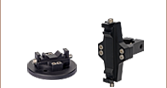
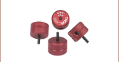
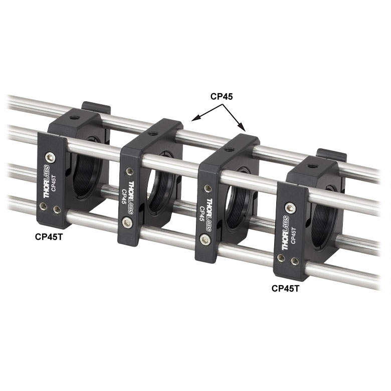
CP45
0.35" Thick Cage Plate
CP45T
0.50" Thick Cage Plate
CP45
Construction Idea
(See the Overview Tab for Details)
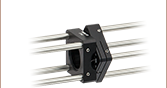
CP45T
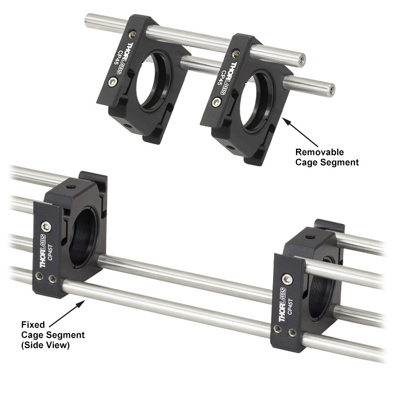
CP45T
Removable
Cage Segment
Fixed
Cage Segment
(Side View)


Please Wait
Click for Details
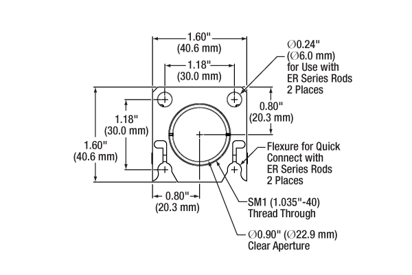
Schematic of Removable Segment Cage Plate (Flexure Cam Locks on Bottom)
| Alternative Size Options |
|---|
| 16 mm Removable Segment Cage Plates |
| 30 mm Removable Segment Cage Plates |
| 60 mm Removable Segment Cage Plates |
Features
- Build Removable Cage Segments for 30 mm Cage Systems
- Accepts Ø6 mm Cage Rods
- Flexure Cam Lock Design Allows Cage Segment Removal
- SM1 (1.035"-40) Internal Thread
- Two SM1RR Retaining Rings Included
- Available in 0.35" and 0.50" Thick Versions
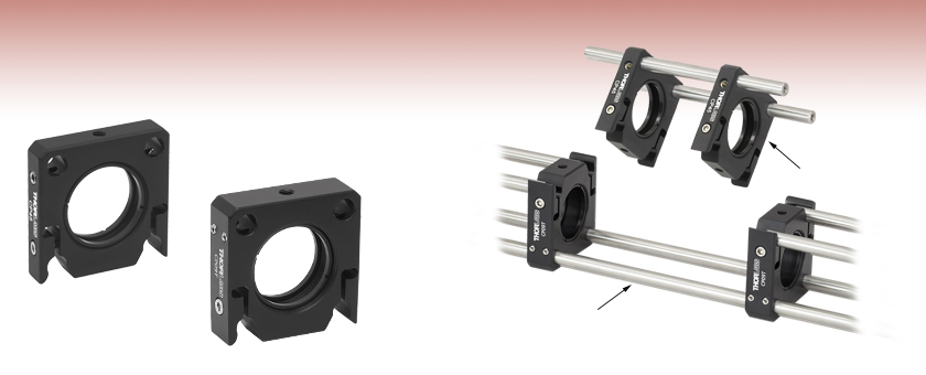
Thorlabs' 30 mm Removable Cage Segment Plates provide the means to extract a portion of a cage system and replace it with another pre-aligned cage segment, as illustrated in the animation and images below. Unlike standard cage plates which require the cage rod to be threaded through the cage plate, these plates allow a segment of a cage system to be removed without disturbing other components in the cage system. The flexure cam locks used in these plates (shown in the schematic to the right) allow the removal of the cage plate in a direction perpendicular to the cage axis, and also securely hold the cage rods prior to locking the segment in place. These cage plates may also be mounted on our Ø1/2" Posts via the 8-32 (M4) threaded mounting holes located on the top and bottom of each part.
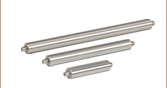
Thorlabs offers 16 mm, 30 mm and 60 mm cage systems designed for Ø1/2", Ø1" and Ø2" optical components (respectively). The parts on this page are compatible with our 30 mm cage system and utilize Ø6 mm ER cage rods.
The above example uses a previous-generation CP09 and CP09T, but
our CP45 and CP45T functions the same way.
Assembling a Removable Cage Segment
Step-by-step instructions for assembling and using a removable cage segment are shown below and is also illustrated in the animation to the right.
1. Use a CP45T(/M) 0.50" thick cage plate to create an interface for a removable cage segment. Pass two cage rods completely through the through holes in the cage plate and secure them using the side-located, 5/64" (2 mm) hex setscrews. The remaining cage rods are passed halfway through the flexure cam locks of the fixed CP45T(/M) cage plates. Do not tighten the flexure cam locks at this point.
2. The removable cage segment can be constructed using the cage plates sold below. Slide the cage rods through the holes in each cage plate and tighten the side-located setscrews with a 5/64" (2.0 mm) hex key. Please note that the cage rods in the removable segment need to be long enough so that they fit into the flexure clamp of the fixed CP45T(/M) cage plates.
3. To lock the removable cage segment once it is in position, tighten all of the flexure mechanisms by tightening the cap head screws with the appropriate hex key. The CP45 cap head screws use a 3/32" hex size, while the CP45T cap head screws use a 5/64" (2 mm) hex size. For the metric cage plates, the CP45/M requires a 2.0 mm hex key, and the CP45T/M needs a 2.5 mm hex key. To remove the segment, loosen the screws on the flexure mechanisms and gently lift the removable segment. An example showing a completed cage system with a removable segment is shown below.
Cage System Overview
The Cage Assembly System provides a convenient way to construct large optomechanical systems with an established line of precision-machined building blocks designed for high flexibility and accurate alignment.
16 mm, 30 mm, and 60 mm Cage System Standards
Thorlabs offers three standards defined by the center-to-center spacing of the cage assembly rods (see image below). The 16 mm cage, 30 mm cage, and 60 mm cage standards are designed to accommodate Ø1/2", Ø1", and Ø2" optics, respectively. Specialized cage plates that allow smaller optics to be directly inserted into our larger cage systems are also available.
Standard Threads
The flexibility of our Cage Assembly System stems from well-defined mounting and thread standards designed to directly interface with a wide range of specialized products. The three most prevalent thread standards are our SM05 Series (0.535"-40 thread), SM1 Series (1.035"-40 thread), and SM2 Series (2.035"-40 thread), all of which were defined to house the industry's most common optic sizes. Essential building blocks, such as our popular lens tubes, directly interface to these standards.
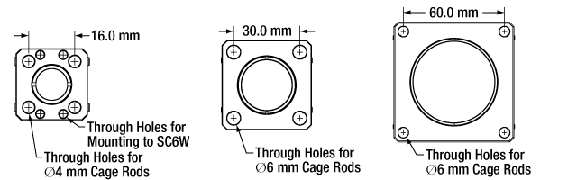
An example of the standard cage plate measurements determining cage system compatibility.
| Standard Cage System Measurements | |||
|---|---|---|---|
| Cage System | 16 mm | 30 mm | 60 mm |
| Thread Series | SM05 | SM1 | SM2 |
| Rod to Rod Spacing | 16 mm (0.63") | 30 mm (1.18") | 60 mm (2.36") |
| Total Length | 25 mm (0.98") | 41 mm (1.60") | 71.1 mm (2.80") |
| Cage Components | ||
|---|---|---|
| Cage Rods | 16 mm | These rods are used to connect cage plates, optic mounts, and other components in the cage system. The SR Series Cage Rods are compatible with our 16 mm cage systems, while the 30 mm and 60 mm cage systems use ER Series Cage Rods. |
| 30 mm | ||
| 60 mm | ||
| Cage Plates | 16 mm | These serve as the basic building blocks for a cage system. They may have SM-threaded central bores, smooth bores sized for industry standard optics or to accommodate the outer profile of our SM Series Lens Tubes, or specialized bores for other components such as our FiberPorts. |
| 30 mm | ||
| 60 mm | ||
| Optic Mounts | 16 mm | Thorlabs offers fixed, kinematic, rotation, and translation mounts specifically designed for our Cage Systems. |
| 30 mm | ||
| 60 mm | ||
| Cage Cubes | 16 mm | These cubes are useful for housing larger optical components, such as prisms or mirrors, or optics that need to sit at an angle to the beam path, such as beamsplitters. Our cage cubes are available empty or with pre-mounted optics. |
| 30 mm | ||
| 60 mm | ||
| Replacement Setscrews | Replacement setscrews are offered for our 16 mm (SS4B013, SS4B025, and SS4B038) and 30 mm (SS4MS5 and SS4MS4) cage systems products. | |
| Post and Breadboard Mounts and Adapters | Mounting options for cage systems can be found on our Cage System Construction pages. Cage Systems can be mounted either parallel or perpendicular to the table surface. | |
| Size Adapters | Cage System Size Adapters can be used to integrate components from different cage system and threading standards. | |
| Specialized Components | Thorlabs also produces specialized cage components, such as Filter Wheels, a HeNe Laser Mount, and a FiberPort Cage Plate Adapter, allowing a wide range of our products to be integrated into cage-mounted optical systems. Explore our Cage Systems Visual Navigation Guide to see the full range of Thorlabs' cage components. | |
| Posted Comments: | |
tcohen
(posted 2012-03-28 12:01:00.0) Response from Tim at Thorlabs to Lalit: Thank you for contacting us. The CP09 is designed for use with our 30mm Cage Systems and 6mm diameter cage rods. The SR3 are our 4mm diameter Mini Series Cage Rods. You can use the ER3 rods (our 6mm diameter version) for compatibility. You can find posts with compatible 8-32 tapped holes at http://www.thorlabs.com//NewGroupPage9.cfm?ObjectGroup_ID=1266. Our 1/2" diameter post holders can be found at http://www.thorlabs.com//NewGroupPage9.cfm?ObjectGroup_ID=1268 and our mounting bases can be found at http://www.thorlabs.com//NewGroupPage9.cfm?ObjectGroup_ID=47. If you have any questions about compatibility, please contact techsupport@thorlabs.com where an Applications Engineer will be more than happy to help you. bslalit
(posted 2012-03-28 01:09:23.0) I am planning to buy CP09- 30 mm Removable Segment Cage Plate, 0.35" Thick and SR3- Mini Series Cage Assembly Rod, 3" Long, Ø4 mm. Can you suggest the holding rods and bases for supporting the above mentioned cage system ??
Regards
Lalit |