

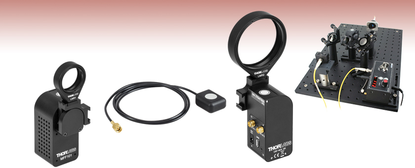
Motorized Filter Flip Mounts
- 90° Flipping Between Two Positions
- Accepts up to Two Optic Holders
- Controlled Using Button, Handset,
External Trigger, or Software - Fully Configurable Input and Output Signals
Application Idea
MFF102
Rear View
A Typical Beam Steering Setup with
a Flip Mount in the Beam Path
Remote Handset (Included)
MFF101
Front View
OVERVIEW
| Specifications | |
|---|---|
| Flip Positions | 0° and 90° |
| Flip Timea | 500 ms to 2800 ms |
| Optic Diameterb | MFF101: 1" MFF102: 2" |
| Flip to Flip Repeatability | 50 μrad |
| Maximum Driftc | 1.0 µm2 |
| Maximum Loadd | 120 g (4.23 oz) |
| Maximum Torque | 0.1 N•m |
| DIG I/O Connector Typee | SMA (2 Places) |
| Power Input | 15 VDC |
| Weight (Excluding Power Supply) |
100 g (3.53 oz) |
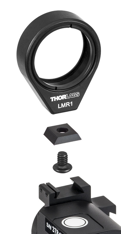
Click to Enlarge
Figure 1.1 Exploded View of Bracket, 8-32 (M4) Screw, and Setscrews for Optic Mount
Please do not try to move the flipper arm by hand when the motor is enabled; doing so will permanently damage the internal gearbox.
Features
- Lens Holder Included
- Compatible with All LMR Series and FMP Series Mounts up to 2.0" Optic Diameter
- Velocity Feedback for Smooth Transitional Motion
- Mechanical Hard Stops for Repeatable Positioning
- 8-32 (M4) Tap for Post Mounting
- Flipper Unit Has Small 30 mm x 30 mm Cross Section
- Includes Remote Handset with 1 m Cable, Kinesis® Software Suite, and Power Supply
These Two-Position, High-Speed Flip Mounts flip lenses, filters, and other optical components into and out of a free-space beam. As shown in Figure 1.2, up to two optic mounts can be attached to the same flipper unit, allowing the user to alternate between optics. The flip action can be controlled in four ways: by the button on the top of the unit, via the included remote handset, via the external SMA connectors, or via a PC running the included software (see the Kinesis Software and Kinesis Tutorials tabs for more information). The flipper position rotates 90° clockwise or counterclockwise when it is toggled and may be toggled either by an absolute signal level (i.e., low and high control voltages correspond to specific flipper positions) or by an edge (i.e., a change in the control voltage level causes the flipper to rotate). The unit has magnetic limit switches at both positions to identify which position the flipper is in.

Click to Enlarge
Figure 1.2 MFF101 Flipper Mount Shown with LMR1 Lens Mount and FMP2 Fixed Optic Mount (FMP2 Sold Separately)
The flipper units offer a compact 30 mm x 30 mm cross section and have two SMA connectors on the side face, marked DIG I/O 1 and DIG I/O 2, which accept input signals from the remote handset or from an external trigger. They can also be configured by a PC running the included Kinesis software to output signals when "In Motion" or "At Position." Software settings can be saved (persisted) within the unit to enable use without a PC.
The MFF101(/M) comes with an LMR1(/M) Ø1" optic mount, which holds an optic with the included SM1RR retaining ring, while the MFF102(/M) comes with an LMR2(/M) Ø2" optic mount, which holds an optic with the included SM2RR retaining ring. Any of our other mounts from the LMR Series or FMP Series can be attached to the flipper mount, so long as their optic diameter does not exceed 2.0" (50.8 mm). As shown in Figure 1.1, a bracket connects the optic mount to the flipper unit. The optic mount is held to the bracket by an 8-32 (M4) screw, and the bracket is held to the flipper unit by a flexure clamp. The flexure clamp tightens using two setscrews that accept the provided 0.035" (0.9 mm) hex key. Two brackets and two 8-32 (M4) screws are provided with each flipper unit.
A bottom-located 8-32 (M4) tapped hole allows the flipper to be mounted on a Ø1/2" post. The flipper is powered by the included 15 V power supply, which ships with a location-specific plug. A 1.5 m (59") long micro-USB to USB cable is also included to connect the flipper to a PC for control and configuration.
The flipper is ideal for use with many types of optics, including mirrors. When used with a mirror, please note that the unit is not recommended for applications requiring better than 100 µrad beam stability. The torque applied to the unit should not exceed 0.1 N•m, and the maximum load capacity, including optic mounts and optics, is 120 g (4.23 oz). The side face of the unit contains an array of vent holes to aid cooling; please ensure that the air flow around these vent holes is not restricted.
PIN DIAGRAM
DIG I/O
SMA Female
Expects and Outputs TTL Signal Levels
TTL Low: 0 V
TTL High: 5 V
KINESIS SOFTWARE
Software
Kinesis Version 1.14.52
The Kinesis Software Package, which includes a GUI for control of Thorlabs' Kinesis system controllers.
Also Available:
- Communications Protocol

Figure 58A Kinesis GUI Screen
Thorlabs offers the Kinesis® software package to drive our wide range of motion controllers. The software can be used to control devices in the Kinesis family, which covers a wide variety of motion controllers ranging from small, low-powered, single-channel drivers (such as the K-Cubes®) to high-power, multi-channel benchtop units and modular 19" rack nanopositioning systems (the MMR60x Rack System).
The Kinesis Software features .NET controls which can be used by 3rd party developers working in the latest C#, Visual Basic, LabVIEW™, or any .NET compatible languages to create custom applications. Low-level DLL libraries are included for applications not expected to use the .NET framework and APIs are included with each install. A Central Sequence Manager supports integration and synchronization of all Thorlabs motion control hardware.
By providing this common software platform, Thorlabs has ensured that users can mix and match any of our motion control devices in a single application, while only having to learn a single set of software tools. In this way, it is perfectly feasible to combine any of the controllers from single-axis to multi-axis systems and control all from a single, PC-based unified software interface.
The software package allows two methods of usage: graphical user interface (GUI) utilities for direct interaction with and control of the controllers 'out of the box', and a set of programming interfaces that allow custom-integrated positioning and alignment solutions to be easily programmed in the development language of choice.
KINESIS TUTORIALS
Thorlabs' Kinesis® software features new .NET controls which can be used by third-party developers working in the latest C#, Visual Basic, LabVIEW™, or any .NET compatible languages to create custom applications.
C#
This programming language is designed to allow multiple programming paradigms, or languages, to be used, thus allowing for complex problems to be solved in an easy or efficient manner. It encompasses typing, imperative, declarative, functional, generic, object-oriented, and component-oriented programming. By providing functionality with this common software platform, Thorlabs has ensured that users can easily mix and match any of the Kinesis controllers in a single application, while only having to learn a single set of software tools. In this way, it is perfectly feasible to combine any of the controllers from the low-powered, single-axis to the high-powered, multi-axis systems and control all from a single, PC-based unified software interface.
The Kinesis System Software allows two methods of usage: graphical user interface (GUI) utilities for direct interaction and control of the controllers 'out of the box', and a set of programming interfaces that allow custom-integrated positioning and alignment solutions to be easily programmed in the development language of choice.
For a collection of example projects that can be compiled and run to demonstrate the different ways in which developers can build on the Kinesis motion control libraries, click on the links below. Please note that a separate integrated development environment (IDE) (e.g., Microsoft Visual Studio) will be required to execute the Quick Start examples. The C# example projects can be executed using the included .NET controls in the Kinesis software package (see the Kinesis Software tab for details).
 |
Click Here for the Kinesis with C# Quick Start Guide Click Here for C# Example Projects Click Here for Quick Start Device Control Examples |
|
LabVIEW
LabVIEW can be used to communicate with any Kinesis-based controller via .NET controls. In LabVIEW, you build a user interface, known as a front panel, with a set of tools and objects and then add code using graphical representations of functions to control the front panel objects. The LabVIEW tutorial, provided below, provides some information on using the .NET controls to create control GUIs for Kinesis-driven devices within LabVIEW. It includes an overview with basic information about using controllers in LabVIEW and explains the setup procedure that needs to be completed before using a LabVIEW GUI to operate a device.
 |
Click Here to View the LabVIEW Guide Click Here to View the Kinesis with LabVIEW Overview Page |
|
Part Number | Description | Price | Availability |
|---|---|---|---|
MFF101/M | Motorized Filter Flip Mount with Ø1" Optic Holder, M4 Tap | $827.46 | Today |
MFF102/M | Motorized Filter Flip Mount with Ø2" Optic Holder, M4 Tap | $827.46 | Today |
MFF101 | Motorized Filter Flip Mount with Ø1" Optic Holder, 8-32 Tap | $827.46 | Today |
MFF102 | Motorized Filter Flip Mount with Ø2" Optic Holder, 8-32 Tap | $827.46 | Lead Time |