

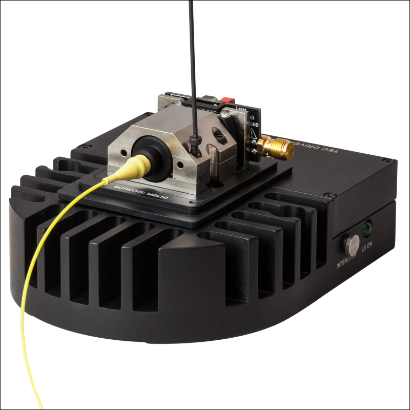
Pigtailed Laser Diode Mount
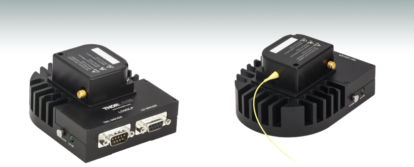
- Mounts Thorlabs’ Pigtailed LDs
- Compact Housing Protects Pigtail
- Integrated Thermistor and TEC
LDM9LP
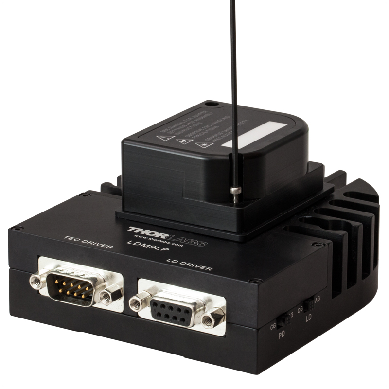
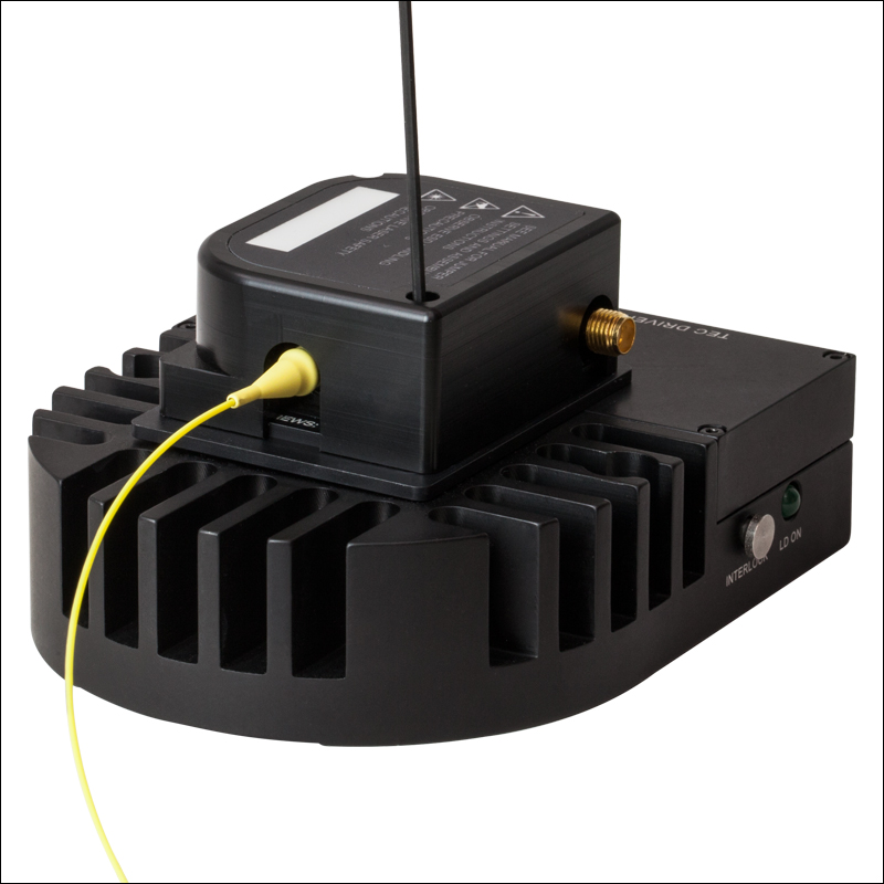
Application Idea
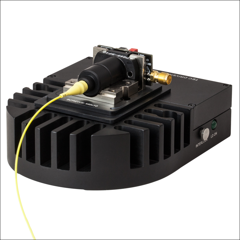
LDM9LP with Mounted
Pigtail Laser Diode
OVERVIEW
Click to Enlarge
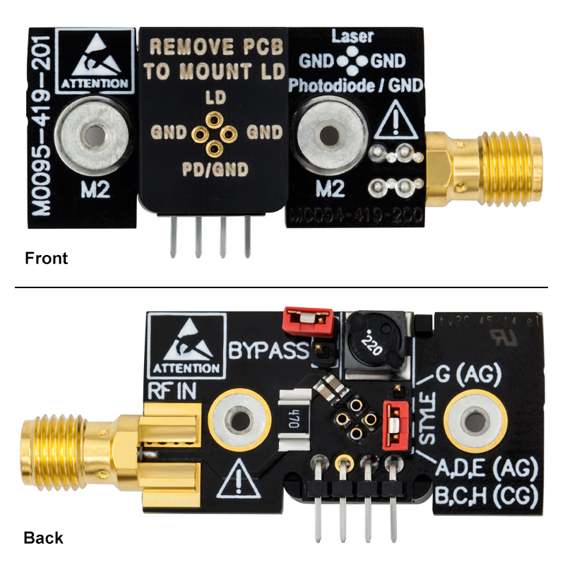
Figure 1.3 Front (Top) and Back (Bottom) Images of the LDM9LP Circuit Board
Features
- Designed for Thorlabs' SM, PM, MM, and DFB Pigtailed Laser Diodesa (Ø5.6 or Ø9 mm, 3 or 4 Pin)
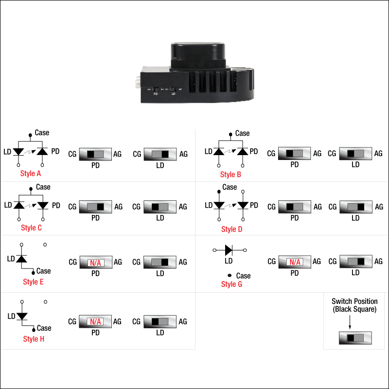
- Supports A, B, C, D, E, G, and H Pin Configurations
- TEC Element Prolongs LD Life and Stabilizes Output Power & Wavelength
- Clamshell Design Eliminates Thermal Gradients Across Diode
- Bias-T Adapter for RF Modulation of Laser Current >200 kHz
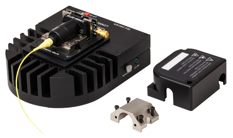
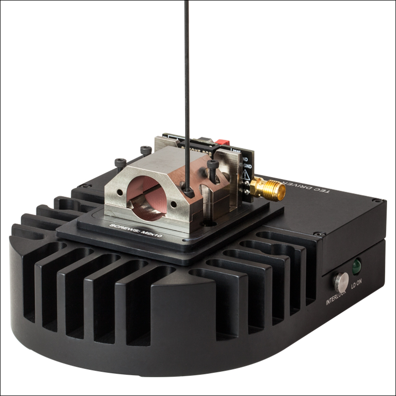
Thorlabs' LDM9LP is an LD and TEC mount designed for use with our 3- and 4-pin pigtailed diodesa. The compact housing protects the pigtail from physical damage, while also offering excellent thermal characteristics. When operating a pigtailed laser diode, temperature control is highly recommended to stabilize the laser's power and wavelength, while also prolonging the life of the laser. Typical laser diode mounts rely on contact between the diode and the mount's cold plate for heat transfer. Pigtailed laser diodes are often recessed in the pigtail's housing, offering poor contact with the cold plate of standard laser diode mounts. The LDM9LP, however, is specifically designed for operating pigtailed laser diodes. Its clamshell design reduces thermal gradients across the diode, while its cold block cradles the pigtail housing for excellent contact and heat transfer. Performance can be further improved by using thermal grease around the pigtail package within the clamshell.
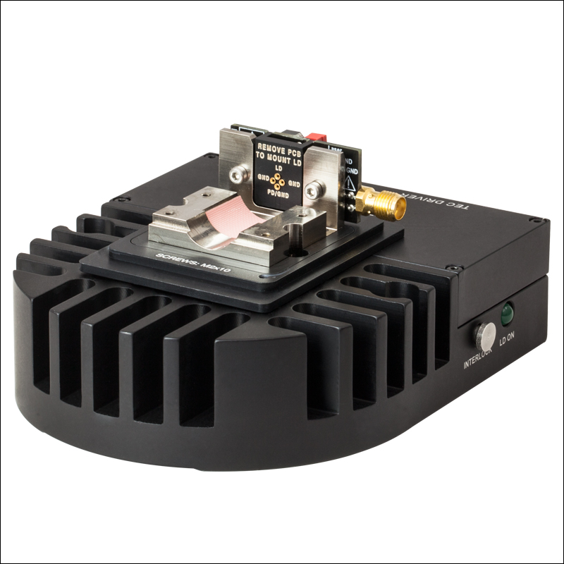
The LDM9LP allows the user to quickly and easily install or remove pigtail diodes from the mount. The back of the circuit board contains a jumper for selecting the appropriate pin configuration of the laser diode (see Figure 1.3). The jumper is labeled with the compatible pin codes for easy reference. Before installing the pigtailed LD, ensure that the jumper is set correctly. Additionally, the front for the circuit board is labeled with a pinout for the socket to help orient the laser diode correctly before mounting (see Mounting Instructions tab for more detail).
Two 1/4" through holes can be used for securing the mount to an optical table with 1/4"-20 or M6 cap screws. It is highly recommended prior to mounting the diode that users verify the diode pin configuration to ensure the laser diode drive pin is secured in the correct socket. Both the inside of the cover and the front of the circuit board contain the pinout for the socket.
DB9 connections interface with all of Thorlabs' LD Current Controllers and TEC Controllers. An RF SMA connector allows access to a Bias-T circuit for RF modulation of the laser's drive current (>200 kHz). For modulation below 200 kHz, current should be modulated through the laser diode controller. A remote interlock jack is provided for the connection of safety devices such as shutters and warning signs.
a. Due to the variety of fiber pigtailed laser diode packages offered by other companies, this mount is only designed for use with Thorlabs products. The mount can also be used with our VHG-stabilized pigtailed laser diode without the protective cover installed; this should not affect diode performance. Thorlabs offers a laser diode pigtailing service; please contact Tech Support for details.
SPECS
| LDM9LP Specifications | |
|---|---|
| Laser Diode Package | Thorlabs' SM, PM, MM, and DFB Pigtailed Laser Diodes (Ø5.6 or Ø9 mm, 3 or 4 Pin) |
| Supported Pin Configurations | A, B, C, D, E, G, & H |
| Laser Current (Max) | 1 A |
| Laser Diode Polarity | Selectable |
| Monitor Diode Polarity | Selectable |
| LD Interface | DB9, Female |
| RF Power (Max) | 500 mW |
| RF Input Impedance | 50 Ω |
| Modulation Frequency (Bias-T) | >200 kHz |
| RF Input Connector | SMA |
| TEC Current (Max) | 4.5 A |
| TEC Voltage (Max) | 3.0 V |
| TEC Heating/ Cooling Capacity | 7 W (Mounted to a 12" × 12" Breadboard) |
| TEC Interface | DB9, Male |
| Temperature Sensor | 10 kΩ Thermistor, ±1% at 25°C, β = 3988 |
| Typical Temperature Range (LD Dependent) | 0 to 70 °C -10 to 70 °C (Mounted to a 12" × 12" Breadboard) |
| Remote Interlock | 2.5 mm Phono Jack |
| Dimensions (L × W × H) | 4.48" × 3.5" × 2.1" (113.8 mm × 88.9 mm × 53.3 mm) |
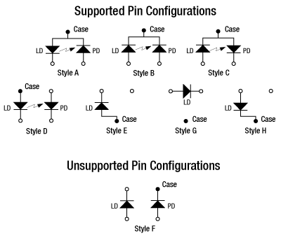
Figure 2.1 A list of the supported pin configurations can be found on the underside of the LDM9LP's cover.
Settings for Supported Laser Diode Pin Types
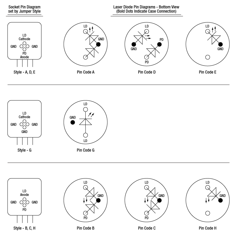
The LDM9LP is compatible with A, B, C, D, E, and G pin configurations. Figure 2.2 illustrates how each pin code should be aligned with the socket on the laser mounting PCB. Two jumper pins, shown in Figure 2.3, also need to be set. Settings are outlined in Tables 2.4 and 2.5. The BYPASS jumper should be set only if the laser is modulated via the LD Driver input.
Click to Enlarge
Figure 2.2 The pin diagrams above show how the laser diode pins should align with the socket on the laser mounting PCB.
Click to Enlarge
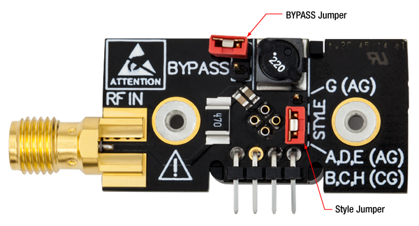
Figure 2.3 The image shows the locations of the STYLE and BYPASS jumper pins. The STYLE jumper pin needs to be set for the pin style of the laser diode in use. The BYPASS jumper should only be set if the laser is modulated via the LD Driver input. Settings are outlined in Tables 2.4 and 2.5.
| Table 2.4 STYLE Jumper | |
|---|---|
| Laser Diode Pin | Jumper Position |
| A, B, C, D, E, or H | Lower 2 Pins |
| G | Upper 2 Pins |
| Table 2.5 BYPASS Jumpera | |
|---|---|
| Operation Mode | Jumper Position |
| Low Noise, No Modulation | Removed |
| RF Modulation via RF IN (BIAS-T) | Removed |
| Modulation via LD Driver Inputb | Set |
PIN DIAGRAMS
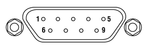
Laser Diode Connector
D-type Female
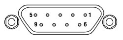
| Pin # | Signal |
|---|---|
| 1 | Interlock and Status Pin (LDC Specific) |
| 2 | Photodiode Cathode |
| 3 | Laser Ground (Case) |
| 4 | Photodiode Anode |
| 5 | Interlock and Status Return |
| 6 | Laser Diode Voltage (-) |
| 7 | Laser Diode Cathode |
| 8 | Laser Diode Anode |
| 9 | Laser Diode Voltage (+) |
TEC Connector
D-type Male
| Pin # | Signal |
|---|---|
| 1 | TEC Lockout (+) |
| 2 | +Thermistor |
| 3 | -Thermistor |
| 4 | +TEC |
| 5 | -TEC and TEC Lockout (-) |
| 6 | Not Connected |
| 7 | Not Connected |
| 8 | Not Connected |
| 9 | Not Connected |
Laser Diode Socket
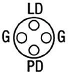
G - Ground
LD - Laser Diode Pin
PD - Photodiode Pin
RF Modulation
SMA Female
This is a 50 Ω input that is AC-coupled directly to the laser through the Bias-T network for modulation frequencies >200 kHz.
GRAPHS
Click to Enlarge
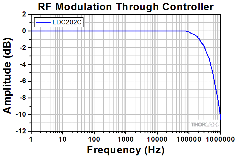
The graph above shows the RF modulation response of the LDM9LP when modulated through an external controller. The LDC202C benchtop LD current controller was used to produce the data shown above.
Click to Enlarge
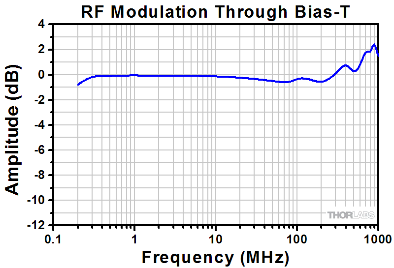
The graph above shows the RF modulation response of the LDM9LP when modulated through the onboard Bias-T SMA input.
MOUNTING INSTRUCTIONS
Click to Enlarge
Step 1: Using a 1.5 mm hex key (included with mount) or balldriver, remove the screws from the cover.
Click to Enlarge
Step 2: Using a 1.5 mm balldriver or hex key, remove the four screws securing the clamshell.
Click to Enlarge
Step 3: Finally, remove the two 1.5 mm hex screws that secure the circuit board.
Click to Enlarge
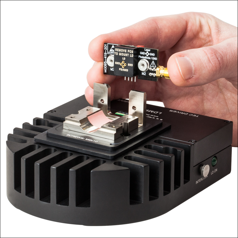
Step 4: Gently pull the circuit board up, removing it from its socket. Before mounting a laser diode to the board, ensure that the jumpers on the back have been correctly set (see the Specs tab for more information).
Click to Enlarge
Step 5: Based on the pin configuration used, set the PD and LD switches on the side of the LDM9LP according to the diagram shown.
Click to Enlarge
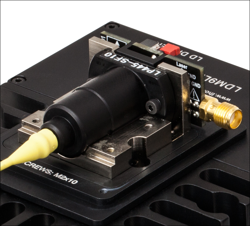
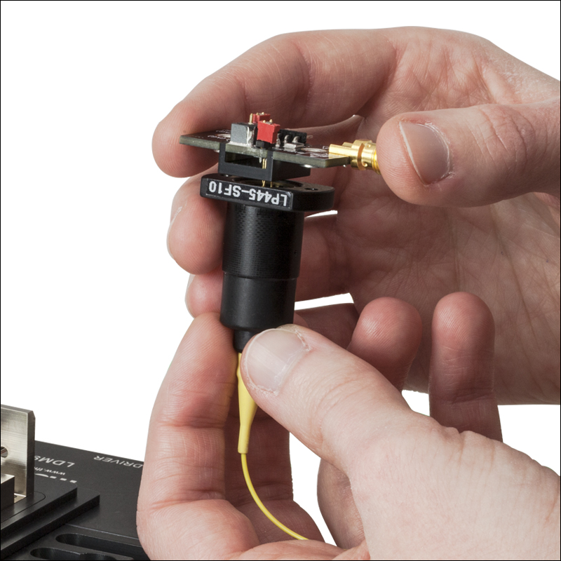
Step 6: Install the LD into the socket, using the pinout on the circuit board to correctly align the LD's pins (see the pin configuration diagram on the Specs tab). Be sure to use a grounding strap (such as the WS01 or WS02) whenever handling LDs.
Click to Enlarge
Step 7: With the diode mounted, carefully plug the circuit board back into its socket. When firmly seated, secure with the two hex screws removed in step 3.
Click to Enlarge
Step 8: Replace all four screws removed in step 2. Be sure to snug up all the screws to ensure proper thermal contact.
Click to Enlarge
Step 9: Replace the screws holding the cover onto the mount.
Click to Enlarge
Step 10: Finally, secure the LDM9LP to a breadboard or optical table with 2 1/4"-20 (M6) cap screws.
SMART PACK

Click to Enlarge
Figure 6.1 LDM9LP Packaging

| Item # | % Weight Reduction |
CO2-Equivalent Reductiona |
|---|---|---|
| LDM9LP | 14.71% | 5.26 kg |
Smart Pack
- Reduce Weight of Packaging Materials
- Increase Usage of Recyclable Packing Materials
- Improve Packing Integrity
- Decrease Shipping Costs
Thorlabs' Smart Pack Initiative is aimed at waste minimization while still maintaining adequate protection for our products. By eliminating any unnecessary packaging, implementing packaging design changes, and utilizing eco-friendly packaging materials for our customers when possible, this initiative seeks to improve the environmental impact of our product packaging. Products listed above are now shipped in re-engineered packaging that minimizes the weight and the use of non-recyclable materials.b As we move through our product line, we will indicate re-engineered packages with our Smart Pack logo.
Pigtailed Laser Diode Mount
Part Number | Description | Price | Availability |
|---|---|---|---|
LDM9LP | LD/TEC Mount for Thorlabs Fiber-Pigtailed Laser Diodes | $800.78 | Today |