

Modular Optical Tweezers
- Configurable for Research and Advanced Lab Courses
- Inverted Microscope Design
- 976 nm Trap Laser; Other Wavelengths Available
- Modules Available for Back Focal Plane Detection
and Fluorescence Microscopy
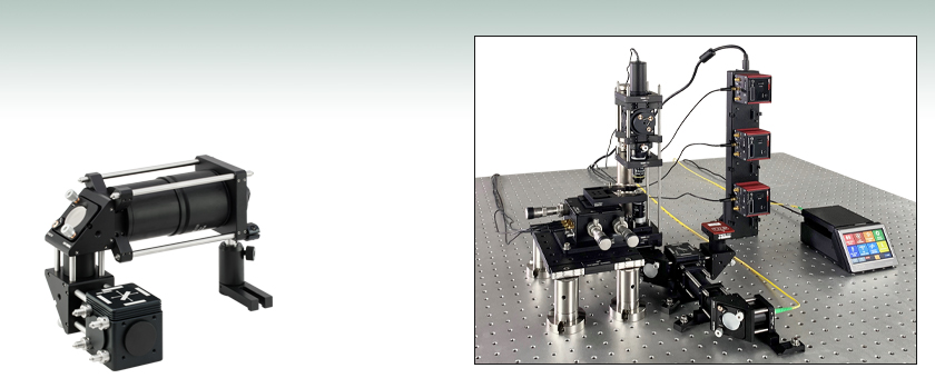
OTKB-FL
Fluorescence
Microscopy Module
(Optional Add-On)
OTKB
Shown Assembled
on a Breadboard
(Not Included)
OVERVIEW
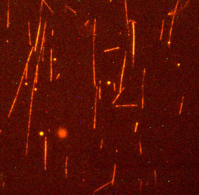
Figure 1.1 Fluorescence Image of an actin network stained with rhodamine phalloidin (Excitation: 540 nm, Emission: 565 nm) acquired by our Modular Optical Tweezers with the optional Fluorescence Module. (Viewed with a N100X-PFO Nikon planfluorite 100X oil immersion objective, 1.3 NA.)
Features
- Complete Optical Trapping System
- Inverted Light Microscope Design Ideal for In Vitro Biological Experiments
- 976 nm, 300 mW Trap Laser with Easy-to-Use Touch Screen Controller
- Nikon 100X Oil Immersion Objective
- 3-Axis Sample Positioning Stage with Integrated Piezo Actuators for Nanometer Resolution
- CMOS Camera with USB Interface for Video Imaging
- Back Focal Plane Detection and Fluorescence Microscopy Modules Available
Thorlabs' OTKB(/M) Modular Optical Tweezers provide users with a tool for trapping and manipulating microscopic-sized objects. These laser-based tweezers, or traps, have been employed in numerous biological experiments. Biological applications for optical tweezers include trapping viruses and bacteria, manipulating cellular structures, patterning of surfaces, and measuring forces of molecular motors and biological molecules such as DNA and proteins. For more details on experiments performed using Thorlabs tweezers, please see the Videos and Publications tabs. The Technology tab provides more details on the functionality of optical tweezers.
Our modular optical tweezers have the flexibility required for experiments conducted in advanced research laboratories. The system is based on an inverted microscope design that provides compatibility with standard samples. It is offered with a CMOS camera for video imaging, and the system can be easily adopted for fluorescence, single-molecule, and other types of microscopy. The advantage to purchasing and assembling this modular system is the versatility it provides over other closed optical tweezers systems. Since the optical tweezers are built using standard Thorlabs components, it is easy to modify or upgrade the system using other standard components.
System Modularity and Assembly
The tweezers system is shipped in pre-assembled segments, which can be assembled on a user-provided optical table or breadboard. A walkthrough of the system setup and alignment is provided on the Videos tab. More details about each of the segments included in the base OTKB system, as well as optional components, can be found on the System tab. A step-by-step assembly instruction manual is included with each system. For an additional cost, we are able to provide a system that has been pre-assembled, aligned, and tested on a breadboard; please contact Tech Support with inquiries.
For initial testing and alignment, the OTKBTK Sample Preparation Kit sold below provides users with everything necessary to prepare a sample and verify that the optical tweezer system is assembled correctly and functioning.
Optional Modules
One of the principal advantages of the OTKB(/M) optical tweezers system over a black box system is the ease with which the design of the optical trap can be modified to add functionality. For example, the OTKBFM can be easily attached to the base OTKB kit to provide the user with a module capable of detecting the back focal plane. This can be used to add trapping force, stiffness, and position measurement capabilities to the OTKB optical trap.
Laser Safety
Whenever operating a laser, it is imperative to pay attention to the classification of the laser and observe appropriate laser safety procedures. Thorlabs' Modular Optical Tweezers System uses a 976 nm, 300 mW laser. Exposure to the laser beam is possible, and the system should be treated as a Class 3B laser. Appropriate safety procedures and care must be taken including, but not limited to, the use of laser safety glasses. More details about the laser classification system and Thorlabs laser safety products can be found in the Laser Safety tab.
SPECS
| Item # | OTKB(/M)a |
|---|---|
| Tweezer Specifications | |
| Trap Force | ~10 pNb |
| Spot Size | 1.1 µm |
| Depth of Focus | 1 µm |
| Laser Wavelength | 976 nm |
| Max Power at Fiber Output | 300 mW |
| Objective Specificationsc | |
| Type | Nikon 100X Immersion Objective |
| Numerical Aperture | 1.25 |
| Input Aperture | Ø5 mm |
| Working Distance | 0.23 mm |
| Wavelength Range | 380 - 1100 nm |
| Recommended Cover Glass Thickness | 0.17 mm |
| Condenser Lens Specifications | |
| Type | Nikon 10X Air Condenser |
| Numerical Aperture | 0.25 |
| Working Distance | 7 mm |
| Wavelength Range | 380 - 1100 nm |
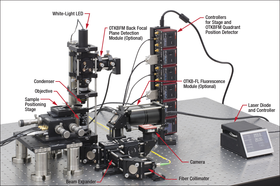
SYSTEM
Click on the OTKB modules in this photo to find out more details.
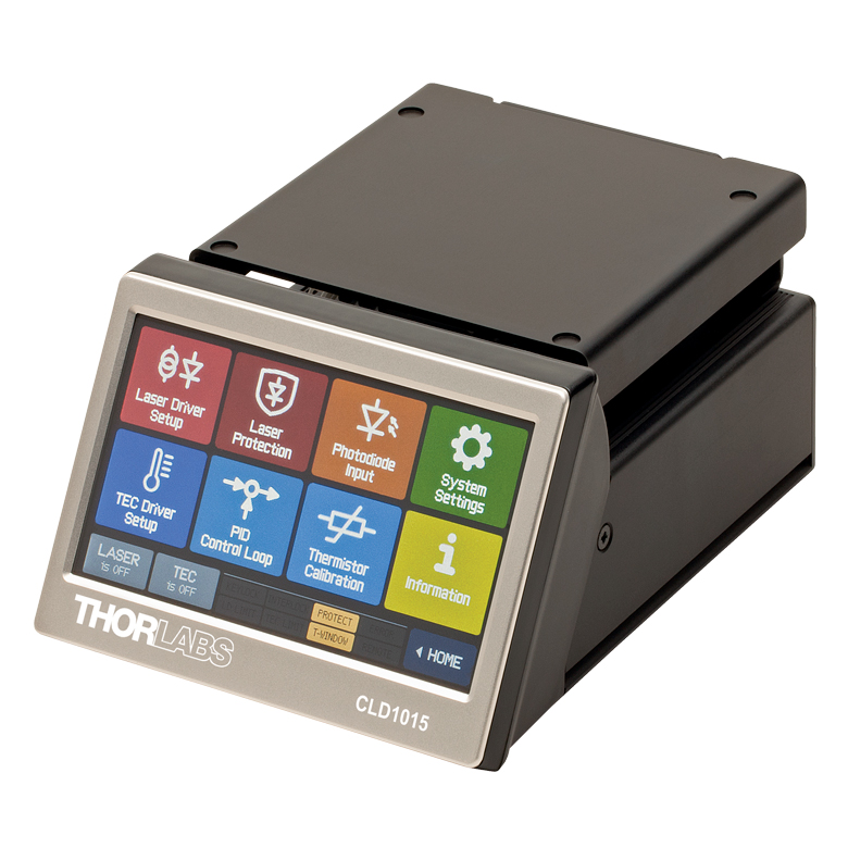
Click to Enlarge
Figure 3.1 Laser Diode Mount
Laser Input and Collimation
The 976 nm trapping laser source is a pigtailed Fiber Bragg Grating (FBG) stabilized single mode laser diode in a hermetically sealed 14-pin butterfly package. The integrated TEC element and thermistor in the butterfly package allow the temperature of the laser to be precisely controlled with our CLD1015 laser diode / TEC controller and mount. This laser, mount, and controller combination was chosen to ensure that the output power of the laser will be very stable, which is important for maintaining a constant trapping force. The laser input is collimated using one of our triplet fiber collimators to provide excellent beam quality and ease of alignment.
Beam Expander
This beam expander is based on Galilean expansion, which minimizes overall space while providing an expansion factor of 3. We use anti-reflection coated achromatic doublets (Item #'s ACN254-050-B and AC254-150-B) that are computer-optimized at infinite conjugate ratios to expand the collimated trapping laser beam. The beam expander uses cage rods assembled in such a way that they allow the user to optimize the divergence of the trapping beam, which can be used to adjust the Z-position of the trapping plane, by allowing up to 12.5 mm adjustment along the optical axis.
Objective and Condenser
A 100X oil immersion Nikon objective lens with a numerical aperture of 1.25 is provided with the OTKB. This lens is used to focus the laser beam down to a spot size of 1.1 µm. For additional applications, such as trapping of higher index polystyrene beads, we offer objectives below with a higher NA of 1.3.
After traveling through the sample, the light is collimated by the condenser lens. The condenser is a Nikon 10X air condenser with a numerical aperture of 0.25.
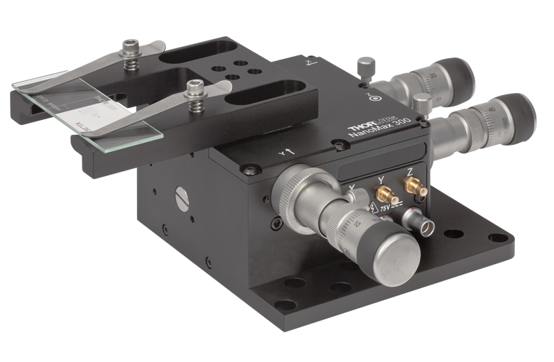
Stage
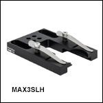
The sample stage consists of a microscope slide holder (Item # MAX3SLH) mounted to a 3-axis (X, Y, Z) translation stage. This stage is then mounted on a translating breadboard, which results in the following capabilities:
- 2.4" (60 mm) of travel perpendicular to the beam path using a TBB0606 (TBB1515/M) translating breadboard. This makes it easy to load the sample and coarsely position it near the trap.
- 4 mm of travel in the X, Y, and Z directions using the MAX311D(/M) NanoMax stage with differential micrometer drives. The coarse adjustment knobs provide 0.5 mm/rev.
- 300 µm of travel in the X, Y, and Z directions using the differential knobs (50 µm/rev) on the NanoMax stage.
- 20 µm of travel in the X, Y, and Z directions using the piezo actuators on the 3-axis stage. 20 nm resolution is possible with the OTKB(/M), as no strain gauge readers are provided. 5 nm resolution can be achieved using the internal strain gauges for positional feedback; two K-Cube® Strain Gauge Readers (Item # KSG101*) are included with the OTKBFM Force Module. Three Piezo Drivers are included in the OTKB(/M).
*The KSG101 is no longer available for individual sale. Please contact Tech Support if a replacement is needed.
Camera Module and LED Source
Visible light from the LED source illuminates the sample and is then imaged on the 1440 x 1080 pixel color CMOS camera (Item # CS165CU1) using an achromatic doublet (Item # AC254-200-A-ML). The dichroic mirror in the light path in combination with a shortpass filter prevents backscattered light from the 976 nm laser from saturating the CMOS sensor after its IR filter has been removed. With the camera, you can acquire still images or video both in color or monochrome black and white.
Controllers for the Sample Stage and the Optional OTKBFM Force Module
The controllers for both the stage and OTKBFM force module are from our compact K-Cube product family. These compact (60 mm x 60 mm x 47 mm [2.4" x 2.4" x 1.9"]) controllers are provided with our USB controller hub, which provides power and single-USB-cable control of up to 6 controllers. The hub can be mounted either vertically (as shown above) or horizontally depending on space constraints.
For additional information on the three piezo drivers included with the kit or the two strain gauge readers provided with the OTKBFM force module, please see the stage or force module sections, respectively.
Click to Enlarge
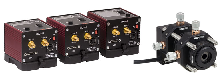
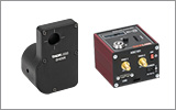
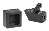
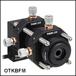
Figure 3.2 OTKBFM Back Focal Plane Detection Module Components:
K-Cube Quadrant Detector and Strain Gauge Readers (Left) and
Optomechanical Module with Quadrant Detector (Right)
Back Focal Plane and Force Acquisition Modules
In order to use an optical tweezers setup for quantitative force measurements, the position of the trapped particle has to be monitored. For high-bandwidth / high-resolution measurements, a Quadrant Position Detector (QPD) can be placed in a plane conjugate to the back focal plane of the condenser. In that case, the signal generated by the QPD is sensitive to the relative displacement of the trapped particle from the trap center, and can be used to determine the position, stiffness, and force of the optical tweezers. The optional OTKBFM module includes a QPD, optomechanics, and controllers to add back focal plane detection to our OTKB modular tweezers setup. The controllers consist of a KPA101 K-Cube Quadrant Detector Reader and two previous-generation KSG101 K-Cube Strain Gauge Readers. This module does not include any data acquisition (DAQ) hardware or software to capture and analyze the data; it is therefore ideal for users who plan to use existing DAQ hardware and analysis software.
Due to the sensitivity of these measurements, we usually recommend using an active isolation support for mounting a system containing an OTKBFM.
For more details on force measurement and calibration techniques, please see the Technology tab.
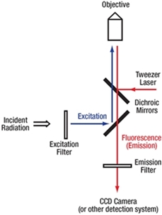
Figure 3.4 Fluorescence Beam Path
Click to Enlarge
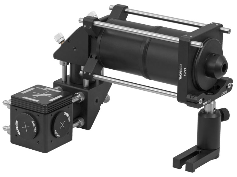
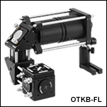
Figure 3.3 OTKB-FL Fluorescence Microscopy Module
Fluorescence Microscopy Module
By combining fluorescence microscopy with optical tweezers, researchers can visualize, manipulate, and rapidly characterize the properties of various samples and cellular structures. Such techniques can be used to detect the arrival of a single molecule into a small volume, detect the conformational changes of cellular structures or bacteria, study elastic properties of a single DNA molecule, demarcate different parts of a larger molecular complex, and measure the response of each to an applied force. Thorlabs provides a tested set of components as a module that enables the addition of such functionalities to our Optical Tweezers Kit, as shown in Figure 3.3.
Fluorescence imaging filters can be easily be inserted or removed with the included quick-change filter cube. To allow users flexibility in choosing fluorophores, an imaging filter set is not included with the fluorescence module; Thorlabs offers fluorescence imaging filters for a variety of common fluorophores that are available separately.
Also recommended is a plan fluorite or semi-apochromatic objective such as the RMS100X-PFO or N100X-PFO (both sold below). The plan fluorite and semi-apochromatic design provides a wider corrected wavelength range ideal for fluorescence microscopy. These objectives have a higher numerical aperture than the standard objective included with the OTKB, allowing them to trap particles like polystyrene that are functionalized and typically used as a probe.
As an application example, consider a sample consisting of a diluted solution of 1.0 µm uniformly FITC-dyed polystyrene beads, with an excitation wavelength of 480 nm and an emission wavelength of 520 nm. The excitation light is selected from a broadband source using a MF475-35 excitation filter, which has a transmission of more than 85% in the 470 - 490 nm range. The light is then coupled into the tweezers system using an MD499 dichroic mirror, which reflects light in the 470 - 490 nm range and transmits light in the 508 - 675 nm range, as shown in Figure 3.4. As with any standard epi-fluorescence technique, the fluorescence light emitted by the sample will be collected by the objective together with any reflected excitation light, which gives a better signal-to-noise ratio than a transmissive detection scheme. The signal then goes back through the dichroics and an MF530-43 emission filter which has a center wavelength of 530 nm and a 43 nm FWHM bandwidth, and is then detected by a CMOS camera. The CMOS camera can also be replaced by a photodiode for quantitative measurements or a scientific camera for higher-quality fluorescence images.
TECHNOLOGY
Click to Enlarge
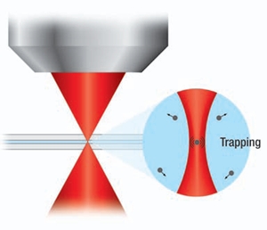
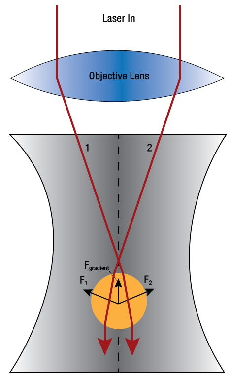
Figure 4.1 Schematic showing the net gradient force on a particle (larger than the wavelength of light) in a focused laser beam.
Basic Theory of Optical Tweezers
Optical Tweezers, or traps as they are often called, are created by using a high numerical aperture objective to tightly focus a laser beam, thereby creating a spot where a particle with dimensions on the order of microns will experience a force due to transfer of momentum from the scattering of photons.
Arthur Ashkin in the early 1970s originally demonstrated that optical forces can manipulate micro-sized dielectric particles in water (A. Ashkin. Phys. Rev. Lett. 24, 156 - 159 [1970] and A. Ashkin et al. Opt. Lett. 1, No. 5, [1986]). This technique has become an important tool in a wide range of fields such as bioengineering, material science, and physics due to its ability to hold and manipulate particles and to measure forces in the femtonewton and piconewton ranges.
The relationship between particle size and the trapping wavelengths presents two regimes to consider when developing a theory to describe optical trapping. In the Mie size regime, the diameter of a trapped particle is much larger than the wavelength of light and trapping can be described using ray optics. Rays of light are refracted as they pass through the particle, exerting a force due to the momentum change. In the case where a particle is not aligned axially in the center of the laser beam, the rays closer to the center of the beam will be more intense and will transfer more momentum to the particle than those rays closer to the edge of the beam. This will apply a lateral "gradient" force to the particle towards the center of the beam. Once the particle is in the center of the beam, the rays refracting through the particle will be symmetric, and the particle will be laterally trapped.
The forces in the axial direction are more complex. As rays are backscattered at the solvent-particle interface, the light will transfer momentum to the particle, leading to a scattering force in the forward direction of the beam. With a particle near the focus of a laser beam, the gradient force Fgradient will act towards the focus, as shown in Figure 4.1. The resulting overall potential has the minimum slightly offset downstream from the focus of the beam. In order to trap particles in the image plane of the microscope, the laser focus has to be slightly offset to compensate for the scattering force.
In the Rayleigh regime, the diameter of the particle is much smaller than the wavelength and the ray theory breaks down. To understand the forces, the trapped particle is considered to be a point dipole. The scattering force arises from absorption and re-radiation, while the gradient force results from the interaction between the inhomogeneous field and the induced dipole (C. N. Keir and M. B. Steven. Review of Scientific Instruments 75, No. 9, 2004).
For particle sizes comparable to the wavelength, neither the Mie theory nor the Rayleigh theory applies; therefore, the electromagnetic field analysis is more complex. There are several references detailing this theory, such as E. Almaas and I. Brevik. J. Opt. Soc. Am. B 12, 2429, 1995; J. P. Barton, J. Appl. Phys. 64, 1632 (1988); P. Zemanek et al. J. Opt. Soc. Am. A 19, 1025 (2002); K. F. Ren et al. Opt. Commun. 108, 343 (1994).
Measuring Forces with Optical Tweezers
The capability of optical tweezers to measure forces on particles offers a unique and valuable tool for studying cell components such as biological proteins and molecular motors. Optical tweezers apply a force toward the focus of the trapping laser beam with a magnitude proportional to the distance of the particle from the focus for small displacements from the center of the trap. As the laser beam passes through a trapped particle, it will be deflected by an amount that depends on the position of the particle relative to the center of the trap. This allows the optical tweezers to be modeled by Hooke's law, Fi = -kixi, where ki is the force (spring) constant and xi is the displacement from the center of the trap.
As the laser beam passes through the sample plane, interference occurs between the light that is transmitted through the trapped particle and the remainder of the light. As a consequence, the interference pattern at the back focal plane of the condenser depends on the distance of the trapped particle to the trap center. The deflection is converted to an electrical signal by a quadrant photodiode, which produces a voltage proportional to the particle position through this back focal plane interferometry (F. Gittes and C. F. Schmidt. Opt. Lett. 23, No. 1, 1998).
The data acquired from the QPD is given in volts. For quantitative force and position measurements it is necessary to determine the detector responsivity factor. One method requires a stuck bead to be moved across the location of the trap while recording the detector voltage. Using the sample stage, steps of known size can be used that then allow plotting of the position signal in volts versus the position signal in microns. When the bead moves across the trap position an S-shaped curve is formed.
Accurate force measurements also depend on precise calibration of the force constant and the responsivity of the particle position detector, which varies with laser power and particle properties. Common methods for ascertaining the force constant are Power Spectral Density (PSD) roll-off, equipartition, and Stokes' drag.
In the PSD roll-off method, the power spectral density of a time series of trapped particle positions (due to Brownian motion) is computed. This is fit to the response of a harmonic oscillator with known damping due to the viscosity of the solvent and is described by the equation:
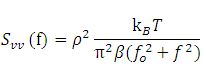
Here, Svv is the uncalibrated power spectrum, ρ is the linear voltage displacement calibration factor, kB is Boltzmann's constant, T is the temperature of the medium, β is the drag coefficient, and f0 is the characteristic corner (roll-off) frequency. A sample PSD curve is shown in Figure 4.1. The PSD roll-off method offers a particularly effective way to discover an inaccurate position detector calibration, since it does not depend on the detector responsivity like the other two methods.
The equipartition method equates the average potential energy of the particle in the trap to the thermal energy of the solvent molecules. The force constant ki is determined using the equation
In the Stokes method, the sample is translated with a range of velocities. A force balance between viscous drag on the particle and the trap force is computed. Since each method relies on a different physical principle, the combined results provide a convenient way to verify the calibration.
VIDEOS
Modular Optical Tweezers Installation
This video provides a walkthrough of the setup and alignment process for the OTKB system. Note that this video contains several previous-generation components, which have since been replaced by their current catalog equivalents. New kits include the components listed in the Shipping List chapter of the manual.
Optical Trapping of Nanoparticles
Bergeron, J., Zehtabi-Oskuie, A., Ghaffari, S., Pang, Y., Gordon, R. Optical Trapping of Nanoparticles. J. Vis. Exp. (71), e4424, doi:10.3791/4424 (2013).
In this video, a modified OTKB system is utilized to trap 20 nm polystyrene nanospheres. This is accomplished by using a double nanohole structure, which produces a large trapping force that allows nanometer-sized particles to be trapped.
An Introduction to Optical Trapping
In this video, Steve Wasserman and Steven Nagel of the Bioinstrumentation Teaching Lab in the MIT Department of Biological Engineering explain the basics of optical trapping and methods for calibrating optical traps using our modular optical tweezers kit.
PUBLICATIONS
The following papers describe research and education using Thorlabs' OTKB Modular Optical Tweezers. To learn how our tweezers might benefit your research, please contact techsupport@thorlabs.com.
Research Articles
Roder, P. B., Manandhar, S., Smith, B. E., Zhou, X., Shutthanandan, V. S. and Pauzauskie, P. J. Photothermal Superheating of Water with Ion-Implanted Silicon Nanowires. Advanced Optical Materials, 3, 1362, 2015.
Benjamin J. Gross and Mohamed Y. El-Naggar. A combined electrochemical and optical trapping platform for measuring single cell respiration rates at electrode interfaces. Rev. Sci. Instrum. 86, 064301, 2015
W. N. Wan Aziz, S. K. Ayop, and S. Riyanto. The Potential of Optical Tweezer (OT) for Viscoelastivity Measurement of Nanocellulose Solution. Jurnal Teknologi 74, 45, 2015.
Gusachenko, I.; Truong, V.G.; Frawley, M.C.; Nic Chormaic, S. Optical Nanofiber Integrated into Optical Tweezers for In Situ Fiber Probing and Optical Binding Studies. Photonics 2, 795, 2015.
Abhay Kotnala, Skyler Wheatona, and Reuven Gordon. Playing the notes of DNA with light: extremely high frequency nanomechanical oscillations. Nanoscale 7, 2295, 2015.
Skyler Wheaton, Ryan M. Gelfand, and Reuven Gordon. Probing the Raman-active acoustic vibrations of nanoparticles with extraordinary spectral resolution. Nature Photonics 9, 68, 2015.
Pick Chung Lau, Zhaozhao Zhu, Robert A. Norwood, Masud Mansuripur, and Nasser Peyghambarian. Thermally robust and blinking suppressed core/graded-shell CdSe/CdSe1−xSx/CdS 'giant' multishell semiconductor nanocrystals. Nanotechnology 24, 475705.
Kuan-Yu Chen, An-Ting Lee, Chia-Chun Hung, Jer-Shing Huang, and Ya-Tang Yang. Transoport and Trapping in Two-Dimensional Nanoscale Plasmonic Optical Lattice. Nano Lett 13, 4418, 2013.
Yuanjie Pang and Reuven Gordon. Optical Trapping of a Single Protien. Nano Lett 12, 402, 2012.
Corey Butler, Shima Fardad, Alex Sincore, Marie Vangheluwe, Matthieu Baudelet, and Martin Richardson. Multispectral optical tweezers for molecular diagnostics of single biological cells. Proc. SPIE 8225 82250C-1, 2012.
Ana Zehtabi-Oskuie, Jarrah Gerald Bergeron, and Reuven Gordon. Flow-dependent double-nanohole optical trapping of 20 nm polystyrene nanospheres. Scientific Reports 2, 966, 2012.
Yuhang Jin and Kenneth B. Crozier. An optical manometer-on-a-chip. Proc. SPIE 8097 80971U, 2011.
Educational Materials
Optical Tweezers. Abbe School of Photonics, Friedrich-Schiller-Universität, Physikalisch-Astronomische-Fakultät, 2010.
Aleksandra Radenovic. Optical Trapping. Advanced Bioengineering Methods Laboratory, École Polytechnique Fédérale de Lausanne.
D. C. Appleyard, K. Y. Vandermeulen, H. Lee, and M. J. Lang. Optical Trapping for Undergraduates. Am. J. Phys. 75 (1), January 2007.
LASER SAFETY
Laser Safety and Classification
Safe practices and proper usage of safety equipment should be taken into consideration when operating lasers. The eye is susceptible to injury, even from very low levels of laser light. Thorlabs offers a range of laser safety accessories that can be used to reduce the risk of accidents or injuries. Laser emission in the visible and near infrared spectral ranges has the greatest potential for retinal injury, as the cornea and lens are transparent to those wavelengths, and the lens can focus the laser energy onto the retina.
 |
 |
 |
 |
 |
 |
 |
 |
 |
Safe Practices and Light Safety Accessories
- Laser safety eyewear must be worn whenever working with Class 3 or 4 lasers.
- Regardless of laser class, Thorlabs recommends the use of laser safety eyewear whenever working with laser beams with non-negligible powers, since metallic tools such as screwdrivers can accidentally redirect a beam.
- Laser goggles designed for specific wavelengths should be clearly available near laser setups to protect the wearer from unintentional laser reflections.
- Goggles are marked with the wavelength range over which protection is afforded and the minimum optical density within that range.
- Laser Safety Curtains and Laser Safety Fabric shield other parts of the lab from high energy lasers.
- Blackout Materials can prevent direct or reflected light from leaving the experimental setup area.
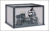
- Thorlabs' Enclosure Systems can be used to contain optical setups to isolate or minimize laser hazards.
- A fiber-pigtailed laser should always be turned off before connecting it to or disconnecting it from another fiber, especially when the laser is at power levels above 10 mW.
- All beams should be terminated at the edge of the table, and laboratory doors should be closed whenever a laser is in use.
- Do not place laser beams at eye level.
- Carry out experiments on an optical table such that all laser beams travel horizontally.
- Remove unnecessary reflective items such as reflective jewelry (e.g., rings, watches, etc.) while working near the beam path.
- Be aware that lenses and other optical devices may reflect a portion of the incident beam from the front or rear surface.
- Operate a laser at the minimum power necessary for any operation.
- If possible, reduce the output power of a laser during alignment procedures.
- Use beam shutters and filters to reduce the beam power.
- Post appropriate warning signs or labels near laser setups or rooms.
- Use a laser sign with a lightbox if operating Class 3R or 4 lasers (i.e., lasers requiring the use of a safety interlock).
- Do not use Laser Viewing Cards in place of a proper Beam Trap.
Laser Classification
Lasers are categorized into different classes according to their ability to cause eye and other damage. The International Electrotechnical Commission (IEC) is a global organization that prepares and publishes international standards for all electrical, electronic, and related technologies. The IEC document 60825-1 outlines the safety of laser products. A description of each class of laser is given below:
| Class | Description | Warning Label |
|---|---|---|
| 1 | This class of laser is safe under all conditions of normal use, including use with optical instruments for intrabeam viewing. Lasers in this class do not emit radiation at levels that may cause injury during normal operation, and therefore the maximum permissible exposure (MPE) cannot be exceeded. Class 1 lasers can also include enclosed, high-power lasers where exposure to the radiation is not possible without opening or shutting down the laser. |  |
| 1M | Class 1M lasers are safe except when used in conjunction with optical components such as telescopes and microscopes. Lasers belonging to this class emit large-diameter or divergent beams, and the MPE cannot normally be exceeded unless focusing or imaging optics are used to narrow the beam. However, if the beam is refocused, the hazard may be increased and the class may be changed accordingly. |  |
| 2 | Class 2 lasers, which are limited to 1 mW of visible continuous-wave radiation, are safe because the blink reflex will limit the exposure in the eye to 0.25 seconds. This category only applies to visible radiation (400 - 700 nm). |  |
| 2M | Because of the blink reflex, this class of laser is classified as safe as long as the beam is not viewed through optical instruments. This laser class also applies to larger-diameter or diverging laser beams. |  |
| 3R | Class 3R lasers produce visible and invisible light that is hazardous under direct and specular-reflection viewing conditions. Eye injuries may occur if you directly view the beam, especially when using optical instruments. Lasers in this class are considered safe as long as they are handled with restricted beam viewing. The MPE can be exceeded with this class of laser; however, this presents a low risk level to injury. Visible, continuous-wave lasers in this class are limited to 5 mW of output power. |  |
| 3B | Class 3B lasers are hazardous to the eye if exposed directly. Diffuse reflections are usually not harmful, but may be when using higher-power Class 3B lasers. Safe handling of devices in this class includes wearing protective eyewear where direct viewing of the laser beam may occur. Lasers of this class must be equipped with a key switch and a safety interlock; moreover, laser safety signs should be used, such that the laser cannot be used without the safety light turning on. Laser products with power output near the upper range of Class 3B may also cause skin burns. |  |
| 4 | This class of laser may cause damage to the skin, and also to the eye, even from the viewing of diffuse reflections. These hazards may also apply to indirect or non-specular reflections of the beam, even from apparently matte surfaces. Great care must be taken when handling these lasers. They also represent a fire risk, because they may ignite combustible material. Class 4 lasers must be equipped with a key switch and a safety interlock. |  |
| All class 2 lasers (and higher) must display, in addition to the corresponding sign above, this triangular warning sign. |  |
|
Modular Optical Tweezers System
Part Number | Description | Price | Availability |
|---|---|---|---|
OTKB/M | Customer Inspired! Modular Optical Tweezers System - Essentials, Metric Threads, 220 VAC | $23,835.59 | Today |
OTKB | Customer Inspired! Modular Optical Tweezers System - Essentials, Imperial Threads, 110 VAC | $23,835.59 | Today |
Back Focal Plane Detection Module
In order to use an optical tweezers setup for quantitative force measurements, the position of the trapped particle has to be monitored. For high-bandwidth / high-resolution measurements, a Quadrant Position Detector (QPD) can be placed in a plane conjugate to the back focal plane of the condenser. In that case, the signal generated by the QPD is sensitive to the relative displacement of the trapped particle from the trap center, and can be used to determine the position, stiffness, and force of the optical tweezers. The optional OTKBFM module includes a QPD, optomechanics, and controllers to add back focal plane detection to our OTKB modular tweezers setup. This module does not include any data acquisition (DAQ) hardware or software to capture and analyze the data; it is therefore ideal for users who plan to use existing DAQ hardware and analysis software.
Due to the sensitivity of these measurements, we usually recommend using an active isolation support for mounting the system containing the OTKBFM.
For more details on force measurement and calibration techniques, please see the Technology tab.
Part Number | Description | Price | Availability |
|---|---|---|---|
OTKBFM | Customer Inspired! Back Focal Plane Detection Module for OTKB and OTKB/M | $3,981.47 | Today |
Fluorescence Microscopy Module
By combining fluorescence microscopy with optical tweezers, researchers can visualize, manipulate, and rapidly characterize the properties of various samples and cellular structures. Such techniques can be used to detect the arrival of a single molecule into a small volume, detect the conformational changes of cellular structures or bacteria, study elastic properties of a single DNA molecule, demarcate different parts of a larger molecular complex, and measure the response of each to an applied force. Thorlabs provides a tested set of components as a module that enables the addition of such functionalities to our Optical Tweezers Kit.
Fluorescence imaging filters can be easily be inserted or removed with the included quick-change filter cube. To allow users flexibility in choosing fluorophores, an imaging filter set is not included with the fluorescence module; Thorlabs offers fluorescence imaging filters for a variety of common fluorophores that are available separately.
Also recommended is a plan fluorite or semi-apochromatic objective such as the RMS100X-PFO or N100X-PFO (both sold below). The plan fluorite and semi-apochromatic design provides a wider corrected wavelength range ideal for fluorescence microscopy. These objectives have a higher numerical aperture than the standard objective included with the OTKB, allowing them to trap particles like polystyrene that are functionalized and typically used as a probe.
The OTKB-FL(/M) is shipped from stock without a light source for users who wish to attach a user-supplied light source. A receptacle for a liquid light guide with a diameter of 3 mm is provided.
For additional application details, please see the Fluorescence Microscopy Module section of the System tab.
Part Number | Description | Price | Availability |
|---|---|---|---|
OTKB-FL/M | Customer Inspired! Fluorescence Module for the OTKB/M, Metric Threads | $2,112.24 | Today |
OTKB-FL | Customer Inspired! Fluorescence Module for the OTKB, Imperial Threads | $2,112.24 | Today |
High Numerical Aperture Objectives
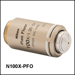
- RMS100X-PFO is an Olympus 1.30 NA Objective
- N100X-PFO is a Nikon 1.30 NA Objective
For applications that involve the optical trapping and manipulation of higher index particles such as polystyrene beads, we recommend a plan fluorite or semi-apochromatic objective that has a higher numerical aperture than the standard 1.25 NA objective included with the OTKB kit. A higher NA objective will enable single particle spectroscopy, such as the trapping of a polystyrene probe bead while simultaneously exciting and observing the fluorescence from the trapped bead.
Part Number | Description | Price | Availability |
|---|---|---|---|
N100X-PFO | 100X Nikon Plan Fluorite Oil Immersion Objective, 1.3 NA, 0.16 mm WD | $3,277.39 | Today |
RMS100X-PFO | 100X Olympus Plan Fluorite Oil Immersion Objective, 1.30 NA, 0.20 mm WD | $3,479.36 | Today |
Slide Holder
Click to Enlarge
- Perfect for Integration into our Optical Tweezer Kit
- Dimensions: 101.6 mm x 68.6 mm x 12.7 mm (4" x 2.7" x 0.5")
The MAX3SLH Microscopy Slide Holder offers your motion control stages the ability to mount petri dishes and glass slides for integration into personalized microscopy setups such as our OTKB optical tweezers. One set of four 6-32 (M3) counterbores and one set of 1/4"-20 (M6) slots allow mounting versatility. The spring clips are also rotatable to accommodate easy swapping of petri dishes and glass slides.
Part Number | Description | Price | Availability |
|---|---|---|---|
MAX3SLH | Customer Inspired! Microscopy Slide Holder | $158.26 | Today |
Sample Preparation Kit
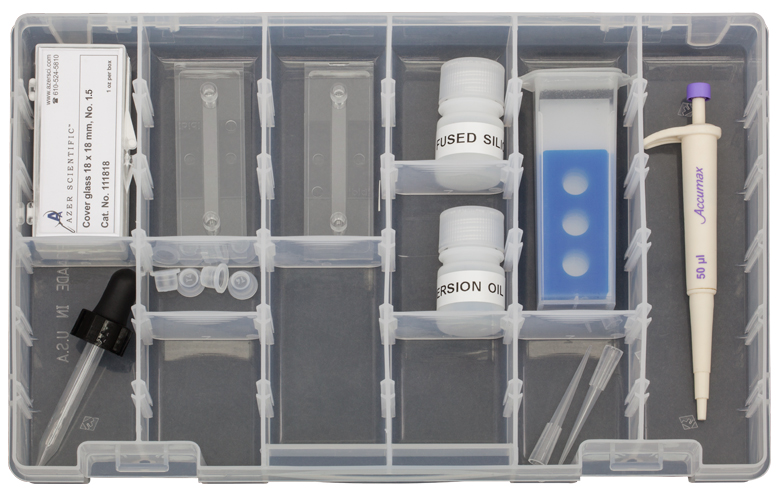
The OTKBTK is designed for use with our OTKB Modular Optical Tweezers and our EDU-OT3 Educational Discovery Kit. It allows users to quickly prepare a sample and test for optical trapping once they have completed construction. Included with the kit are the following:
- Non-Drying Immersion Oil for Microscopy, Cargille Type LDF
- Not for Use with EDU-OT3(/M)
- Non-Functionalized Fused Silica Beads in Deionized Water, Ø2.06 µm, 2 g/ml
- Mini Pipette with a 50 µL Volume
- Two Plastic Slides with Built-In Channel, 400 µm Height, 100 µL Volume
- 5 Microscope Glass Slides with Reaction Wells, Ø10 mm, 20 µm Deep
- 100 Pieces of 18 mm x 18 mm Cover Glass, No. 1.5 Thickness
- Dropper for Immersion Oil
Part Number | Description | Price | Availability |
|---|---|---|---|
OTKBTK | Optical Tweezer Kit - Sample Preparation Kit | $184.44 | Today |