

Manual Fiber Polarization Controllers
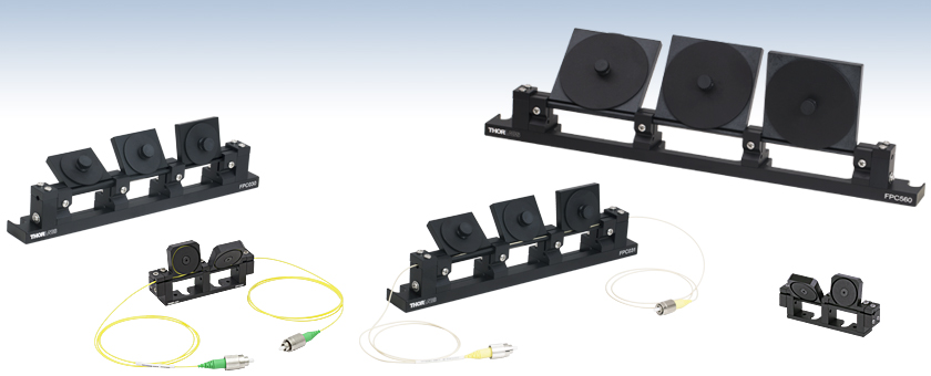
- Polarization Over Full Poincaré Sphere
- Controllers Available Preloaded with 1 of 6 Fibers
- Empty Controllers for Ø900 µm Jacketed Fiber
- FC/PC or FC/APC Connectors
FPC030
Empty Controller with Ø1.06" Loops
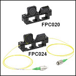
FPC024
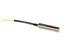
Preloaded with HI1060 Fiber, FC/APC
FPC031
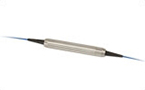
Preloaded with ClearCurve® Fiber, FC/PC
FPC560
Empty Controller with Ø2.2" Loops
FPC020
Empty Controller with Ø0.71" Loops
OVERVIEW
The animation above shows an ideal case. The fractional retardance of each paddle depends upon many factors, including the wavelength, the number of fiber loops, and the fiber type. For more details, please see the Operation tab.
Features
- Convert Between Linear, Circular, and Elliptical Polarization States
- Operates over Full Fiber Bandwidth
- Empty Controllers for Ø900 µm Jacketed FC/PC or FC/APC Patch Cables
- Preloaded Controllers with FC/PC- or FC/APC-Terminated Fibers (2.0 mm Narrow Key)
- Three Loop Diameters Available
- Three-Paddle Controllers: Ø1.06" or Ø2.2"
- Two-Paddle Controllers: Ø0.71"
Thorlabs' Fiber Polarization Controllers use stress-induced birefringence produced by wrapping the fiber around two or three spools to create independent wave plates that will alter the polarization of the transmitted light in a single mode fiber. The fast axis of the fiber is in the plane of the spool, allowing an arbitrary input polarization state to be adjusted by rotating the paddles. See Video 1.1 and the Operation tab for more details.
The controllers are available in a 3-paddle configuration with either 1.06" or 2.2" diameter loops as well as a mini 2-paddle configuration with 0.71" diameter loops. Thorlabs offers an empty controller in each style to allow the user to insert single mode fiber with a Ø900 µm jacket, such as a bare fiber, FC/PC patch cable, or FC/APC patch cable. To ensure proper usage of the controllers, fiber cables must be long enough to achieve the recommended number of loops; see the Operation tab for more details. For fibers with higher bend loss, we recommend using the version with the largest spools (FPC560), thereby causing the least amount of bending. Controllers are also available preloaded with one of six fiber types, although the preloaded fiber may be replaced with another fiber should a different wavelength range be required for future applications. See the Specs tab for the available configurations.
We also offer In-Line Polarization Controllers. These controllers create a single continously variable wave plate similar to a Soleil-Babinet compensator, enabling polarization control over the full Poincaré sphere.
| Fiber Polarization Control Selection Guide | ||||||
|---|---|---|---|---|---|---|
| Polarization Controllers | Linear Polarizers | |||||
 |
 |
 |
 |
 |
 |
 |
| Motorized Fiber Polarization Controllers | Manual Paddle Fiber Polarization Controllers | In-Line Manual Fiber Polarization Controller | Free-Space FiberBench | Faraday Mirrors | In-Line Fiber Polarizers | Polarizing Fiber |
SPECS
3-Paddle Polarization Controllers, Ø56 mm Loop
| Item # | FPC560 | FPC563 | FPC564 | FPC561 | FPC562 |
|---|---|---|---|---|---|
| Number of Paddles | 3 | ||||
| Loop Diameter | 2.2" (56 mm) | ||||
| Paddle Rotation | ±117.5° | ||||
| Footprint (L x W) | 12.50" x 1.00" (317.5 mm x 25.4 mm) in Narrowest Configuration 12.50" x 4.85" (317.5 mm x 123.2 mm) in Widest Configuration |
||||
| Specifications for Preloaded Fiber (As Shipped by Thorlabs) | |||||
| Fiber | None | 780HP | HI1060-J9 | SMF-28-J9 | |
| Included Patch Cable | None | P3-780Y-FC-5 | P3-1064Y-FC-5 | P1-SMF28Y-FC-5 | P3-SMF28Y-FC-5 |
| Operating Wavelength Rangea | N/A | 780 - 970 nm | 980 - 1650 nm | 1260 - 1625 nm | |
| Design Wavelengthb | N/A | 780 nm and 850 nm | 980 nm and 1064 nm | 1310 nm and 1550 nm | |
| Mode Field Diameter | N/A | 5.0 ± 0.5 µm @ 850 nm | 5.9 ± 0.3 µm @ 980 nm 6.2 ± 0.3 µm @ 1060 nm |
9.2 ± 0.4 µm @ 1310 nm 10.4 ± 0.5 µm @ 1550 nm |
|
| Cladding Diameter | N/A | 125 ± 1 µm | 125 ± 0.5 µm | 125 ± 0.7 µm | |
| Coating Diameter | N/A | 245 ± 15 µm | 245 ±10 µm | 242 ± 5 µm | |
| Cutoff Wavelength | N/A | 730 ± 30 nm | 920 ± 50 | <1260 nm | |
| NA | N/A | 0.13 | 0.14 | 0.14 | 0.14 |
| Jacketing | N/A | Ø900 µm Hytrel®c Tubing | Ø900 µm Tight Buffer | ||
| Loop Configuration | N/A | 2 Loops - 4 Loops - 2 Loops | 3 Loops - 6 Loops - 3 Loops | ||
| Total Fiber Lengthd | N/A | 5 m +7/-0 cm | 5 m | ||
| Fiber Lead Lengthe | N/A | 180 cm | 145 cm | ||
| Connectorsf | N/A | FC/APC | FC/PC | FC/APC | |
| Bend Loss | N/A | ≤0.1 dB | |||
3-Paddle Polarization Controllers, Ø27 mm Loop
| Item # | FPC030 | FPC033 | FPC034 | FPC031 | FPC032 |
|---|---|---|---|---|---|
| Number of Paddles | 3 | ||||
| Loop Diameter | 1.06" (27 mm) | ||||
| Paddle Rotation | ±117.5° | ||||
| Footprint (L x W) | 8.50" x 1.00" (215.9 mm x 25.4 mm) in Narrowest Configuration 8.50" x 2.51" (215.9 mm x 63.8 mm) in Widest Configuration |
||||
| Specifications for Preloaded Fiber (As Shipped by Thorlabs) | |||||
| Fiber | None | 780HP | HI1060-J9 | CCC1310-J9 | |
| Included Patch Cable | None | P3-780Y-FC-2 | P3-1064Y-FC-2 | -b | |
| Operating Wavelength Rangea | N/A | 780 - 970 nm | 980 - 1650 nm | 1260 - 1625 nm | |
| Design Wavelengthc | N/A | 780 nm and 850 nm | 980 nm and 1064 nm | 1310 nm and 1550 nm | |
| Mode Field Diameter | N/A | 5.0 ± 0.5 µm @ 850 nm | 5.9 ± 0.3 µm @ 980 nm 6.2 ± 0.3 µm @ 1060 nm |
8.6 ± 0.4 µm @ 1310 nm 9.7 ± 0.5 µm @ 1550 nm |
|
| Cladding Diameter | N/A | 125 ± 1 µm | 125 ± 0.5 µm | 125 ± 0.7 µm | |
| Coating Diameter | N/A | 245 ± 15 µm | 245 ± 10 µm | 242 ± 5 µm | |
| Cutoff Wavelength | N/A | 730 ± 30 nm | 920 ± 50 nm | ≤1260 nm | |
| NA | N/A | 0.13 | 0.14 | 0.14 | 0.14 |
| Jacketing | N/A | Ø900 µm Hytrel®d Tubing | Ø900 µm Tight Buffer | ||
| Loop Configuration | N/A | 1 Loop - 2 Loops - 1 Loop | 3 Loops - 2 Loops - 3 Loops | 4 Loops - 3 Loops - 4 Loops | |
| Total Fiber Lengthe | N/A | 2 m +7/-0 cm | 2 m | ||
| Fiber Lead Lengthf | N/A | 83 cm | 66 cm | 70 cm | |
| Connectorsg | N/A | FC/APC | FC/PC | FC/APC | |
| Bend Loss | N/A | ≤0.1 dB | |||
2-Paddle Fiber Polarization Controllers, Ø18 mm Loop
| Item # | FPC020 | FPC021 | FPC022 | FPC023 | FPC024 | FPC025 |
|---|---|---|---|---|---|---|
| Number of Paddles | 2 | |||||
| Loop Diameter | 0.71" (18 mm) | |||||
| Paddle Rotation | ±143° | |||||
| Foot Print (L x W) | 3.06" x 0.50" (77.6 mm x 12.7 mm) in Narrowest Configuration 3.06" x 1.75" (77.6 mm x 44.5 mm) in Widest Configuration |
|||||
| Specifications for Preloaded Fiber (As Shipped by Thorlabs) | ||||||
| Fiber | None | SM450 | SM600 | 780HP | HI1060-J9 | CCC1310-J9 |
| Included Patch Cable | None | P3-460Y-FC-2 | P3-630Y-FC-2 | P3-780Y-FC-2 | P3-1064Y-FC-2 | -b |
| Operating Wavelength Rangea | N/A | 488 - 633 nm | 633 - 780 nm | 780 - 970 nm | 980 - 1650 nm | 1260 - 1625 nm |
| Design Wavelengthc | N/A | 488 nm | 633 nm | 780 nm and 850 nm | 980 nm and 1064 nm | 1310 nm and 1550 nm |
| Mode Field Diameter | N/A | 2.8 - 4.1 µm @ 488 nm | 3.6 - 5.3 µm @ 633 nm | 5.0 ± 0.5 µm @ 850 nm | 5.9 ± 0.3 µm @ 980 nm 6.2 ± 0.3 µm @ 1060 nm |
8.6 ± 0.4 µm @ 1310 nm 9.7 ± 0.5 µm @ 1550 nm |
| Cladding Diameter | N/A | 125 ± 1.0 µm | 125 ± 1.0 µm | 125 ± 1.5 µm | 125 ± 0.5 µm | 125 ± 0.7 µm |
| Coating Diameter | N/A | 245 ± 15 µm | 245 ± 15 µm | 245 ± 15 µm | 245 ± 10 µm | 242 ± 5 µm |
| Cutoff Wavelength | N/A | 350 - 470 nm | 550 ± 50 nm | 730 ± 30 nm | 920 ± 50 nm | ≤1260 nm |
| NA | N/A | 0.10 - 0.14 | 0.10 - 0.14 | 0.13 | 0.14 | 0.14 |
| Jacketing | N/A | Ø900 µm Hytrel®d Tubing | Ø900 µm Tight Buffer | |||
| Loop Configuration | N/A | 3 Loops - 2 Loops | 3 Loops - 1 Loop | 4 Loops - 1 Loop | 2 Loops - 4 Loops | 1 Loop - 2 Loops |
| Total Fiber Lengthe | N/A | 2 m +7/-0 cm | ||||
| Fiber Lead Lengthf | N/A | 83 cm | 85 cm | 88 cm | 80 cm | 83 cm |
| Connectorsg | N/A | FC/APC | ||||
| Bend Loss | N/A | ≤0.1 dB | ||||
OPERATION
These manual polarization controllers utilize stress-induced birefringence to create two or three independent fractional wave plates to alter the polarization in single mode fiber that is looped around two or three independent spools to create the independent fractional wave plates (fiber retarders). The amount of birefringence induced in the fiber is a function of the fiber cladding diameter, the spool diameter (fixed), the number of fiber loops per spool, and the wavelength of the light. (NOTE: The desired birefringence is induced by the loop in the fiber, not by the twisting of the fiber paddles). The fast axis of the fiber, which is in the plane of the spool, is adjusted with respect to the transmitted polarization vector by manually rotating the paddles to twist the fiber. To transform an arbitrary input polarization state into another arbitrary output polarization state, a combination of three paddles (a quarter-wave plate, a half-wave plate, and a quarter-wave plate) or two paddles (quarter-wave plate and a half-wave plate) can be used. Because a three-paddle configuration decouples the two quarter-wave plates, more polarization states can be achieved compared to a two-paddle configuration. The retardance of each paddle may be estimated from the following equation:

Here, φ is the retardance, a is a constant (0.133 for silica fiber), N is the number of loops, d is the fiber cladding diameter, λ is the wavelength, and D is the loop diameter. While this equation is for bare fiber, the solution for Ø900 µm jacketed fiber will be similar enough that the results for this equation can still be used (i.e., the solution will not vary by a complete loop N for Ø900 µm jacketed fiber).
Recommended Number of Loops
The recommended number of loops, fiber, and patch cables for several wavelengths is given in the following tables. These combinations come close to the desired quarter-wave retardation:
| Wavelength | # of Loops for ~1/4λ Retardation | Recommended Fiber | Recommended Patch Cables |
||
|---|---|---|---|---|---|
| Ø18 mm | Ø27 mm | Ø56 mm | |||
| 480 nm | 3 Loops | N/A | 3 Loops | 460HP or SM450 | P1-460Y-FC-2, P3-460Y-FC-2 |
| 630 nm | 3 Loops | 2 Loops | 4 Loops | 630HP or S630-HP | P1-630Y-FC-2, P3-630Y-FC-2 |
| 780 nm | 4 Loops | 1 Loop | 2 Loops | 780HP, S630-HP, or SM600 | P1-780Y-FC-2 P3-780Y-FC-2 P3-780Y-FC-5 |
| 850 nm | 3 Loops | 1 Loop | 2 Loops | 780HP or SM800-5.6-125 | P1-780Y-FC-2, P3-780Y-FC-2, P3-780Y-FC-5 |
| 980 nm | 2 Loops | 3 Loops | 2 Loops | 980HP, HI1060-J9, or 1060XP | P1-1064Y-FC-2, P3-1064Y-FC-2, P3-1064Y-FC-5 |
| 1060 nm | 2 Loops | 3 Loops | 2 Loops | 980HP, HI1060-J9, or 1060XP | P1-1064Y-FC-2, P3-1064Y-FC-2, P3-1064Y-FC-5 |
| 1310 nm | 1 Loop | 4 Loops | 3 Loops | SMF-28-J9 or CCC1310-J9 | P1-SMF28Y-FC-2, P1-SMF28Y-FC-5 ,P3-SMF28Y-FC-2, P3-SMF28Y-FC-5 |
| 1550 nm | 1 Loop | 2 Loops | 3 Loops | SMF-28-J9 or CCC1310-J9 | P1-SMF28Y-FC-2 P1-SMF28Y-FC-5 P3-SMF28Y-FC-2 P3-SMF28Y-FC-5 |
These combinations come close to the desired half-wave retardation:
| Wavelength | # of Loops for ~1/2λ Retardation | Recommended Fiber | Recommended Patch Cables |
||
|---|---|---|---|---|---|
| Ø18 mm | Ø27 mm | Ø56 mm | |||
| 480 nm | 2 Loops | 3 Loops | 2 Loops | 460HP or SM450 | P1-460Y-FC-2, P3-460Y-FC-2 |
| 630 nm | 1 Loop | 4 Loops | 3 Loops | 630HP or S630-HP | P1-630Y-FC-2, P3-630Y-FC-2 |
| 780 nm | 1 Loop | 2 Loops | 4 Loops | 780HP, S630-HP, or SM600 | P1-780Y-FC-2 P3-780Y-FC-2 P3-780Y-FC-5 |
| 850 nm | 1 Loop | 2 Loops | 4 Loops | 780HP or SM800-5.6-125 | P1-780Y-FC-2, P3-780Y-FC-2, P3-780Y-FC-5 |
| 980 nm | 4 Loops | 2 Loops | 4 Loops | 980HP, HI1060-J9, or 1060XP | P1-1064Y-FC-2, P3-1064Y-FC-2, P3-1064Y-FC-5 |
| 1060 nm | 4 Loops | 2 Loops | 4 Loops | 980HP, HI1060-J9, or 1060XP | P1-1064Y-FC-2, P3-1064Y-FC-2, P3-1064Y-FC-5 |
| 1310 nm | 2 Loops | 3 Loops | 6 Loops | SMF-28-J9 or CCC1310-J9 | P1-SMF28Y-FC-2, P1-SMF28Y-FC-5, P3-SMF28Y-FC-2, P3-SMF28Y-FC-5 |
| 1550 nm | 2 Loops | 3 Loops | 6 Loops | SMF-28-J9 or CCC1310-J9 | P1-SMF28Y-FC-2 P1-SMF28Y-FC-5 P3-SMF28Y-FC-2 P3-SMF28Y-FC-5 |
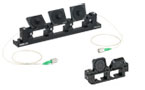
Three-Paddle Polarization Controllers
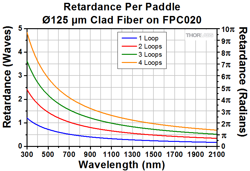
A three-paddle polarization controller combines a quarter-wave plate, half-wave plate, and quarter-wave plate in series to transform an arbitrary polarization state into another polarization state. The first quarter-wave plate would transform the input polarization state into a linear polarization state. The half-wave plate would rotate the linear polarization state, and the last quarter-wave plate would transform the linear state into an arbitrary polarization state. This is illustrated in Video 1.1 on the Overview tab. Therefore, adjusting each of the three paddles (fiber retarders) allows complete control of the output polarization state over a broad range of wavelengths from 500 to 1600 nm). Using FPC030 as an example, a plot of calculated retardation per paddle versus wavelength is shown in Figure 3.1 for a fiber with a cladding diameter of 125 μm. For fiber with a cladding diameter of 80 μm, the retardation per paddle versus wavelength is shown in Figure 3.2. The FPC030 has a loop diameter of 27 mm.
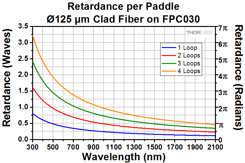
Click to Enlarge
Figure 3.1 Plot of the retardance per paddle for silica fiber with Ø125 µm cladding on the FPC030, which has a loop diameter of 27 mm.
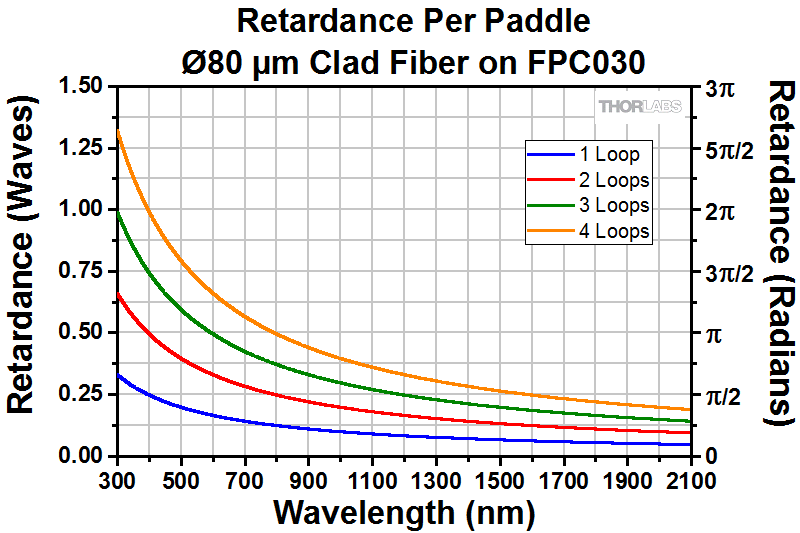
Click to Enlarge
Figure 3.2 Plot of the retardance per paddle for silica fiber with Ø80 µm cladding on the FPC030, which has a loop diameter of 27 mm.
Figures 3.3 and 3.4 show the results for Ø125 µm and Ø80 µm clad fiber, respectively, for the FPC560 controller, which has three paddles with a loop diameter of 56 mm. The larger loop diameter is ideal for fibers with higher bend loss.
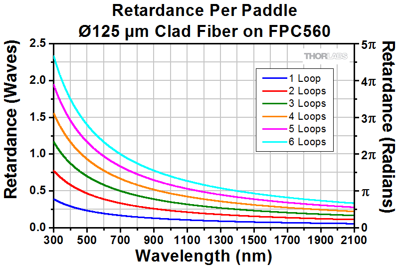
Click to Enlarge
Figure 3.3 Plot of the retardance per paddle for silica fiber with Ø125 µm cladding on the FPC560, which has a loop diameter of 56 mm.
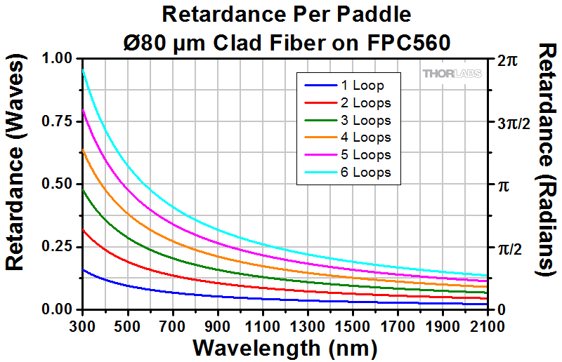
Click to Enlarge
Figure 3.4 Plot of the retardance per paddle for silica fiber with Ø80 µm cladding on the FPC560, which has a loop diameter of 56 mm.
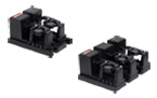
Miniature Two-Paddle Polarization Controller
The miniature two-paddle polarization controllers use a quarter-wave plate and a half-wave plate to transform an arbitrary polarization state into another polarization state. In the two-paddle configuration, however, the control of the polarization will be coupled between the two paddles and therefore it may be difficult to achieve a specific polarization state. The design of the FPC020 allows complete control of the output polarization state over a broad range of wavelengths. Figures 3.5 and 3.6 show the calculated retardation per paddle for Ø125 µm and Ø80 µm clad bare fiber, respectively, for the FPC020, which has a loop diameter of 18 mm.
Click to Enlarge
Figure 3.5 Plot of the retardance per paddle for bare silica fiber with Ø125 µm cladding on the FPC020, which has a loop diameter of 18 mm.

Click to Enlarge
Figure 3.6 Plot of the retardance per paddle for bare silica fiber with Ø80 µm cladding on the FPC020, which has a loop diameter of 18 mm.
LAB FACTS

Click for Details
Figure 4.2 Poincaré sphere showing the polarization rotation from a three paddle polarization controller.
Click to Enlarge
Figure 4.1 Forces produced by the fiber controller paddle
Thorlabs Lab Facts: Using Fiber Paddles to Manipulate Polarization
We present laboratory measurements of the influence on the output polarization state from a fiber due to rotation and twist forces from the fiber polarization controller (FPC). This controller utilizes the effects of stress-induced birefringence to create changes in the polarization of light traveling through a fiber under stress. The stress can be caused either through twisting or rotating [1], as shown in Figure 4.1. It was found that by using the appropriate number of loops on each paddle that the stress-induced birefringence can be adjusted continuously. This then allows for any arbitrary input polarization state to be rotated into any desired output polarization state. We detail the procedures necessary to achieve a desired output polarization, and plot the change in the polarization on a Poincaré sphere to illustrate the steps necessary in reaching a desired polarization state.
For our experiment, we used the previous-generation S1FC1310 Fabry-Perot Benchtop Laser (1310 nm) as the light source and coupled it into a SMF-28-J9 Ø900 µm tight-buffer fiber. The fiber was mounted through a FPC030 Fiber Polarization Controller, and the output was collimated into a free-space beam with a F220FC-C fiber collimator. From here the beam was measured, either directly by a polarimeter or through an analyzer assembly consisting of a WPQ05M-1310 λ/4 wave plate, a LPNIR100 linear polarizer, and a PM100D power meter.

Figure 4.2 summarizes the measured results for manipulating the polarization of light in a fiber as a function of rotation and twist forces and is shown on the Poincaré sphere. The colored lines represent one of the three paddles of the FPC030 and correspond to the colored numbers of Figure 4.1. To produce quarter-wave plate behavior, the fiber needed to be looped around a paddle two times, and for half-wave plate behavior it was 3 times. For the results presented in Figure 4.2, we used the FPC030 FPC in a 2-3-2 loop configuration. As shown in Figure 4.2, starting at any arbitrary polarization state, it is possible to achieve any desired polarization state through rotating each paddle through a number of iterations. This manipulation of the polarization by the FPC does not produce intrinsic loss nor back reflections; instead stress-induced birefringence is utilized as a mechanism for rotating the polarization of light in fiber. Data is presented for each of the paddles of the FPC and the polarization changes due to these are mapped out on Poincaré spheres. For details on the experimental setup employed and the results obtained, please click here.
[1] R. Ulrich, A. Simon, “Polarization optics of twisted single-mode fibers” Appl. Opt. 18, 2241-2251 (1979).
INSIGHTS

Insights into Polarization Conventions
Scroll down to read about:
- Labels Used to Identify Perpendicular and Parallel Components
Click here for more insights into lab practices and equipment.
Labels Used to Identify Perpendicular and Parallel Components
When polarized light is incident on a surface, it is often described in terms of perpendicular and parallel components. These are orthogonal to each other and the direction in which the light is propagating (Figure 190A).
Labels and symbols applied to the perpendicular and parallel components can make it difficult to determine which is which. Table 190B identifies, for a variety of different sets, which label refers to the perpendicular component and which to the parallel.
| Table 190B Common Labels for Orthogonal Linear Polarization States | ||
|---|---|---|
| Labels | Notes |
|
| Perpendicular | Parallel | |
| s | p | Senkrecht (s) is 'perpendicular' in German. Parallel begins with 'p.' |
| TE | TM | TE: Transverse electric field. |
| ⊥ | // | ⊥ and // are symbols for perpendicular and parallel, respectively. |
| σ | π | The Greek letters corresponding to s and p are σ and π, respectively. |
| Sagittal | Tangential | A sagittal plane is a longitudinal plane that divides a body. |
The perpendicular and parallel directions are referenced to the plane of incidence, which is illustrated in Figure 190A for a beam reflecting from a surface. Together, the incident ray and the surface normal define the plane of incidence, and the incident and reflected rays are both contained in this plane. The perpendicular direction is normal to the plane of incidence, and the parallel direction is in the plane of incidence.
The electric fields of the perpendicular and parallel components oscillate in planes that are orthogonal to one another. The electric field of the perpendicular component oscillates in a plane perpendicular to the plane of incidence, while the electric field of the parallel component oscillated in the plane of incidence. The polarization of the light beam is the vector sum of the perpendicular and parallel components.
Normally Incident Light
Since a plane of incidence cannot be defined for normally incident light, this approach cannot be used to unambiguously define perpendicular and parallel components of light. There is limited need to make the distinction, since under conditions of normal incidence the reflectivity is the same for all components of light.
Date of Last Edit: Mar. 5, 2020
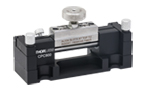
3-Paddle Polarization Controllers, Ø56 mm Loop


Click Here to Enlarge
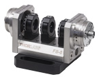
Figure G1.1 A 3-paddle controller mounted on an optical table utilizing the 1/4"-20 (M6) screw slots.

Click to Enlarge
Figure G1.2 Polarization Controller Mounting Features
- 3 Paddles Provide 3 Independently Rotatable Wave Plates
- Ø2.2" (56 mm) Fiber Loops
- Each Paddle Provides ±117.5° of Rotation
- Available Empty or Preloaded With FC/PC- or FC/APC-Terminated Fiber
- Replacement Ø900 µm Jacketed FC/PC or FC/APC Patch Cables Available
Thorlabs' 3-Paddle Fiber Polarization Controllers use stress-induced birefringence to create independent wave plates to alter the polarization of the transmitted light in single mode fiber. The three fractional wave plates are created by looping the fiber around three independent spools (see the Operation tab for details). For the polarization controllers preloaded with fiber, the three paddles are configured to approximate a quarter-wave, half-wave, and quarter-wave plate, in that order, when used at the design wavelength (see Table G1.3).
The FPC560 fiber polarization controller is empty, allowing customers to insert single mode fiber with a Ø900 µm jacket. Additionally, we have Ø900 µm jacketed FC/PC and FC/APC patch cables available from stock that are suitable for use with these controllers. The other four controllers come preloaded with fiber. The fibers in the preloaded controllers can also be removed and replaced by the user in the event that the controllers are needed for a new application in the future. To ensure proper usage of the controllers, fiber cables must be long enough to achieve the recommended number of loops; see the Operation tab for more details.
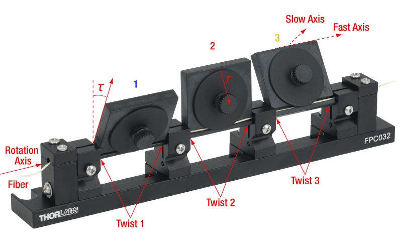
The fiber is secured around three spools and by a clamp at each end of the controller. The spool covers have knobs for easy loading and unloading and the clamps are held in place by 4-40 screws. If needed, the top of the clamps can be completely removed to load terminated fibers. To secure the controller to the optical table, two clearance slots for 1/4"-20 (M6) cap screws are positioned 12.00" (304.8 mm) apart on the base plate. All 3-paddle controllers have three additional long slots along their base for more mounting options to both metric and imperial optical tables. Two slots at either end of the base accept 1/4"-20 (M6) cap screws (see Figure G1.1), while a centered slot accepts 4-40 (M3) cap screws. A schematic of the mounting features described is shown in Figure G1.2.
| Table G1.3 Key Specifications | |||||||
|---|---|---|---|---|---|---|---|
| Item #a | Wavelength Rangeb |
Design Wavelengthc |
Fiber | Included Patch Cabled |
Fiber Lead Lengthe |
Connectorsf | Loop Diameter |
| FPC560 | N/A | N/A | N/A | N/A | N/A | N/A | 2.2" (56 mm) |
| FPC563 | 780 - 970 nm | 780 nm and 850 nm | 780HP | P3-780Y-FC-5 | 180 cm | FC/APC | |
| FPC564 | 980 - 1650 nm | 980 nm and 1064 nm | HI1060-J9 | P3-1064Y-FC-5 | FC/APC | ||
| FPC561 | 1260 - 1625 nm | 1310 nm and 1550 nm | SMF-28-J9 | P1-SMF28Y-FC-5 | 145 cm | FC/PC | |
| FPC562 | P3-SMF28Y-FC-5 | FC/APC | |||||
Part Number | Description | Price | Availability |
|---|---|---|---|
FPC560 | Fiber Polarization Controller, 3 Ø56 mm Paddles, No Fiber | $288.54 | Today |
FPC563 | Fiber Polarization Controller, 3 Ø56 mm Paddles, 780HP, FC/APC Connectors | $407.67 | Today |
FPC564 | Fiber Polarization Controller, 3 Ø56 mm Paddles, HI1060-J9, FC/APC Connectors | $407.67 | Today |
FPC561 | Fiber Polarization Controller, 3 Ø56 mm Paddles, SMF-28e+, FC/PC Connectors | $345.73 | Today |
FPC562 | Fiber Polarization Controller, 3 Ø56 mm Paddles, SMF-28e+, FC/APC Connectors | $372.42 | Today |
3-Paddle Polarization Controllers, Ø27 mm Loop

Click Here to Enlarge
Figure G2.1 A 3-paddle controller mounted on an optical table utilizing the 1/4"-20 (M6) screw slots.
Click to Enlarge
Figure G2.2 Polarization Controller Mounting Features
- 3 Paddles Provide 3 Independently Rotatable Wave Plates
- Ø1.06" (27 mm) Fiber Loops
- Each Paddle Provides ±117.5° of Rotation
- Available Empty or Preloaded With FC/PC- or FC/APC-Terminated Fiber
- Replacement Ø900 µm Jacketed FC/PC or FC/APC Patch Cables Available
Thorlabs' 3-Paddle Fiber Polarization Controllers use stress-induced birefringence to create independent wave plates to alter the polarization of the transmitted light in single mode fiber. The three fractional wave plates are created by looping the fiber around three independent spools (see the Operation tab for details). For the polarization controllers preloaded with fiber, the three paddles are configured to approximate a quarter-wave, half-wave, and quarter-wave plate, in that order, when used at the design wavelength (see Table G2.3).
The FPC030 fiber polarization controller is empty, allowing customers to insert a single mode fiber with a Ø900 µm jacket. Additionally, we have Ø900 µm jacketed FC/PC and FC/APC patch cables available from stock that are suitable for use with these controllers. The other four controllers come preloaded with fiber. The fibers in the preloaded controllers can also be removed and replaced by the user in the event that the controllers are needed for a new application in the future. To ensure proper usage of the controllers, fiber cables must be long enough to achieve the recommended number of loops; see the Operation tab for more details. For fibers with higher bend loss, we recommend using our Ø56 mm polarization controllers, thereby causing the least amount of bending.
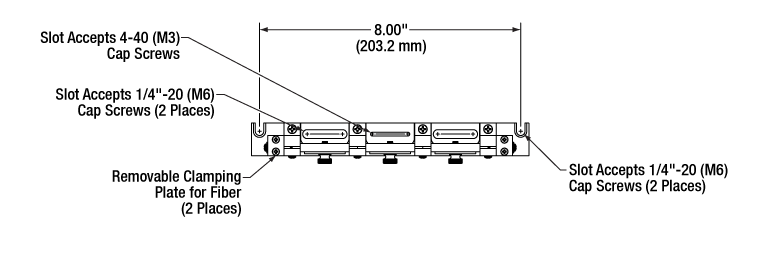
The fiber is secured around three spools and by a clamp at each end of the controller. The spool covers have knobs for easy loading and unloading and the clamps are held in place by 4-40 screws. If needed, the top of the clamps can be completely removed to load terminated fibers. To secure the controller to the optical table, two clearance slots for 1/4"-20 (M6) cap screws are positioned 8.00" (203.2 mm) apart on the base plate. All 3-paddle controllers have three additional long slots along their base for more mounting options to both metric and imperial optical tables. Two slots at either end of the base accept 1/4"-20 (M6) cap screws (see Figure G2.1), while a centered slot accepts 4-40 (M3) cap screws. A schematic of the mounting features described is shown in Figure G2.2.
| Table G2.3 Key Specifications | |||||||
|---|---|---|---|---|---|---|---|
| Item #a | Wavelength Rangeb |
Design Wavelengthc |
Fiber | Included Patch Cabled |
Fiber Lead Lengthe |
Connectorsf | Loop Diameter |
| FPC030 | N/A | N/A | N/A | N/A | N/A | N/A | 1.06" (27 mm) |
| FPC033 | 780 - 970 nm | 780 nm and 850 nm | 780HP | P3-780Y-FC-2 | 83 cm | FC/APC | |
| FPC034 | 980 - 1650 nm | 980 nm and 1064 nm | HI1060-J9 | P3-1064Y-FC-2 | 66 cm | FC/APC | |
| FPC031 | 1260 - 1625 nm | 1310 nm and 1550 nm | CCC1310-J9 | -g | 70 cm | FC/PC | |
| FPC032 | FC/APC | ||||||
Part Number | Description | Price | Availability |
|---|---|---|---|
FPC030 | Fiber Polarization Controller, 3 Ø27 mm Paddles, No Fiber | $259.29 | Today |
FPC033 | Fiber Polarization Controller, 3 Ø27 mm Paddles, 780HP, FC/APC Connectors | $379.70 | Today |
FPC034 | Fiber Polarization Controller, 3 Ø27 mm Paddles, HI1060-J9, FC/APC Connectors | $379.70 | Today |
FPC031 | Fiber Polarization Controller, 3 Ø27 mm Paddles, ClearCurve® Fiber, FC/PC Connectors | $316.51 | Today |
FPC032 | Fiber Polarization Controller, 3 Ø27 mm Paddles, ClearCurve® Fiber, FC/APC Connectors | $344.45 | Today |
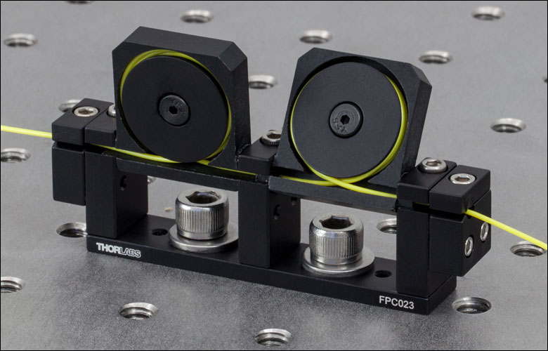
2-Paddle Polarization Controllers, Ø18 mm Loop
Click to Enlarge
Figure G3.1 2-Paddle Controller Mounted on an Optical Table
- 2 Paddles Provide 2 Independently Rotatable Wave Plates
- Ø0.71" (18 mm) Fiber Loops
- Each Paddle Provides ±143° of Rotation
- Available Empty or Preloaded With FC/APC-Terminated Fiber
- Replacement Ø900 µm Jacketed FC/PC or FC/APC Patch Cables Available
Thorlabs' Miniature 2-Paddle Fiber Polarization Controllers use stress-induced birefringence to create two independent wave plates to alter the polarization of the transmitted light in single mode fiber. The two fractional wave plates are created by looping the fiber around two independent spools (see the Operation tab for details). For the polarization controllers preloaded with fiber, the paddles are configured to approximate a quarter-wave plate and a half-wave plate when used at the design wavelength (see Table G3.2).
The FPC020 polarization controller is empty, allowing customers to insert a single mode fiber with a Ø900 µm jacket. Additionally, we have Ø900 µm jacketed FC/PC and FC/APC patch cables available from stock that are suitable for use with these controllers. The other four controllers come preloaded with fiber. The fibers in the preloaded controllers can also be removed and replaced by the user in the event that the controllers are needed for a new application in the future. To ensure proper usage of the controllers, fiber cables must be long enough to achieve the recommended number of loops; see the Operation tab for more details. To ensure proper usage of the controllers, fiber cables must be long enough to achieve the recommended number of loops; see the Operation tab for more details.
The fiber is secured around two removable spools with a lip and two clamps at the ends of the controller. The clamps and spools are held in place by 4-40 cap screws, compatible with an 3/32" hex key or balldriver. Two clearance slots for 1/4"-20 or M6 cap screws are positioned 1" (25.4 mm) apart on the base for mounting the controller to an optical table (Figure G3.1).
| Table G3.2 Key Specifications | |||||||
|---|---|---|---|---|---|---|---|
| Item #a | Wavelength Rangeb |
Design Wavelengthc |
Fiber | Included Patch Cabled |
Fiber Lead Lengthe |
Connectorsf | Loop Diameter |
| FPC020 | N/A | N/A | N/A | N/A | N/A | N/A | 0.71" (18 mm) |
| FPC021 | 488 - 633 nm | 488 nm | SM450 | P3-460Y-FC-2 | 83 cm | FC/APC | |
| FPC022 | 633 - 780 nm | 633 nm | SM600 | P3-630Y-FC-2 | 85 cm | ||
| FPC023 | 780 - 970 nm | 780 nm and 850 nm | 780HP | P3-780Y-FC-2 | 88 cm | ||
| FPC024 | 980 - 1650 nm | 980 nm | HI1060-J9 | P3-1064Y-FC-2 | 80 cm | ||
| FPC025 | 1260 - 1625 nm | 1310 nm | CCC1310-J9 | -g | 83 cm | ||
Part Number | Description | Price | Availability |
|---|---|---|---|
FPC020 | Fiber Polarization Controller, 2 Ø18 mm Paddles, No Fiber | $250.41 | Today |
FPC021 | Fiber Polarization Controller, 2 Ø18 mm Paddles, SM450, FC/APC Connectors | $391.49 | Today |
FPC022 | Fiber Polarization Controller, 2 Ø18 mm Paddles, SM600, FC/APC Connectors | $391.49 | Today |
FPC023 | Fiber Polarization Controller, 2 Ø18 mm Paddles, 780HP, FC/APC Connectors | $391.49 | Today |
FPC024 | Fiber Polarization Controller, 2 Ø18 mm Paddles, HI1060-J9, FC/APC Connectors | $391.49 | Today |
FPC025 | Fiber Polarization Controller, 2 Ø18 mm Paddles, CCC1310-J9, FC/APC Connectors | $391.49 | Today |