Vytran® Automated Glass Processors
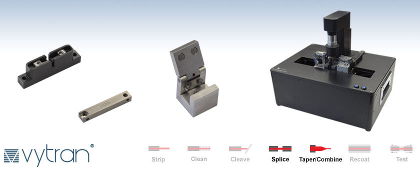
- Fabricate Fiber Splices, Tapers, Terminations, Couplers, and Combiners
- Automated XY and Rotational Alignment
- Two Models for Optical Fiber Claddings up to Ø1.25 mm or Ø1.7 mm
GPX3400
Glass Processor Workstation
VHT1
Transfer Clamp
VHB05
Fiber Holder Top Insert for LED Illumination
FTAV6
Graphite Filament Assembly
Glass Processor Workstations, Filaments, Inserts, and Accessories All Sold Separately

Please Wait
Click for Details
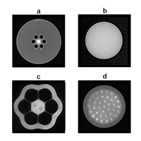
End-view images of fibers with internal structure. Shown are a) photonic crystal fiber, b) image guides, c) 6+1 PM fiber combiner, and d) 37 to 1 fiber combiner.
Features
- Fabricate Splices, Tapers, Terminations, Couplers, and Combiners
- Automated XY and Rotation Alignment
- Compatible with Single Mode, Multimode, Polarization-Maintaining, and Specialty Fibers (See Applications Tab for Examples)
- Create Low-Loss (~0.02 dB) Splices in Standard Glass Fibers (See Specs Tab for Details)
- Side-View/End-View Imaging using True Core Imaging™ Technology
- Software with Process Development GUI and Splice Process Library (See Software Tab for More Information)
Build Your System
- Glass Processor Workstation for Fibers with Claddings up to Ø1.25 mm (GPX3400) or up to Ø1.7 mm (GPX3600)
- Choose from Graphite, Iridium, and Tungsten Filament Assemblies (One FTAV4 Graphite Filament Pre-Installed in System)
- Choose Top and Bottom Inserts (Two Top Inserts and Two Bottom Inserts Required; See Fiber Holder Inserts Tab for More Information)
- Optional Multi-Fiber Holder Bottom Inserts (For Making Couplers or Combiners)
- Optional Fluorine-Doped Capillary Tubes (For Making Specialty Couplers or Combiners)
- Optional Liquid Cooling System for Tapering Applications (One Included with the GPX3600)
- Optional Fiber Taper Software and Handling Fixtures
- Optional Fiber Combiner Loading Fixture
- Optional Ultrasonic Cleaner for Preparing Fibers Prior to Splicing
- Optional Mountable Gooseneck Light
Thorlabs' Vytran® Optical Fiber Glass Processors are versatile platforms designed for fabricating splices, tapers, couplers, terminations, and combiners using optical fibers. The glass processors sold on this page feature automated pre-splice alignment for the XY position of the fiber edge and rotational orientation of the fiber core. These systems are ideal for splicing applications involving polarization-maintaining fibers, photonic crystal fibers, and other specialty fibers with microstructured cores. The GPX3400 glass processor is compatible with fibers up to Ø1.25 mm cladding while the higher power GPX3600 can process fibers up to Ø1.7 mm cladding.
These glass processors incorporate a filament-based furnace assembly that provides a uniform and precisely controlled, high-temperature heat source. Because filament material and size can be interchanged easily (ten different filament options are available below), a wide range of fiber cladding diameters and specialty fiber types can be accommodated using the same system. Precise control over fiber position and orientation enables a number of advanced fiber processing applications from low-loss splicing in dissimilar fibers to the creation of adiabatic fiber tapers, fiber terminations, or fused fiber couplers (please see the Applications tab for examples).
True Core Imaging
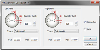
These fiber processing systems employ True Core Imaging technology to provide high-resolution images for fiber measurement and alignment. A digital CCD camera and mirror tower are integrated into the fiber processing workstation to allow for clear side-view and end-view images (see example images to the right) of the fiber cladding and core. This imaging feature allows for automated measurement of fiber properties (core/cladding diameters, cleave angle, etc.) and provides feedback for the automated alignment system. The VHB00 or VHB05 top insert (sold below) is required in order to use automated end-view alignment.
Options and Accessories
A complete glass processor requires the purchase of a glass processor workstation (choose one below), two top inserts (sold separately below), two bottom inserts (sold separately below), and a >99.999% purity argon gas tank (not available from Thorlabs). The Fiber Holder Inserts tab has information to aid in choosing pairs of fiber holder inserts, as well as insert installation instructions. An FTAV4 Graphite Filament (for Ø125 - Ø600 µm cladding) is included with each glass processor; additional filaments made from different materials or for other fiber cladding diameters are sold separately below. See the Tutorial Videos tab above for videos on how to install filaments and perform filament maintenance. An ultrasonic cleaner for preparing fibers for splicing can be purchased separately below.
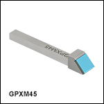
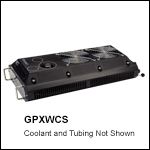
Several optional add-ons are available for these systems to enable specialized applications. The GPXWCS Liquid Cooling System helps cool the furnace assembly when the filaments are used for extended heating times and is recommended for customers interested in creating long fiber tapers. It comes included with the high-power GPX3600 and can be purchased as an add-on for the GPX3400. Multi-fiber holder bottom inserts are used when fabricating couplers or combiners and are designed to hold two or three fibers in close proximity during heating. The GPXM45 bottom insert with 45° mirror is an optional accessory for providing an additional method for inspection of fiber end faces and alignment of fiber components. Thorlabs also offers a Fiber Taper Software Add-On and Taper Handling Fixtures (sold below), which include software application files and fixture upgrades that enable high repeatability when fabricating and handling microtapers, nanotapers, fused fiber couplers, or wavelength division multiplexers. The software add-on and fixtures can be purchased separately or together as a kit. We also offer the GPXCFXL Fixture that supports the positioning of fiber bundles during combiner fabrication. The GPXL1 Gooseneck Light is available for end-view illumination of the fiber or for general lighting during alignment. It can be mounted to the left or right side of the workstation.
| Compatible Vytran Fiber Processing Systems | |||||||
|---|---|---|---|---|---|---|---|
| Fiber Preparation Station (Strip and Clean) |
Large-Diameter Fiber Cleavers |
Portable Large-Diameter Fiber Cleavers |
Large-Diameter Fiber Splicer |
CO2 Laser Glass Processing System (Splice and Taper) |
Automated Glass Processing Systems with Integrated Cleaver (Cleave, Splice, and Taper) |
Automated Glass Processing Systems (Splice and Taper) |
Recoaters, Proof Testers, and Recoaters with Proof Testers |
| Item # | GPX3400 | GPX3600 |
|---|---|---|
| Splicing Specifications | ||
| Silica Fiber Types (Non PM) | Single Mode, Multimode, Photonic Crystal, Large Mode Area, Non-Circulara | |
| Silica Fiber Types (PM) | PANDA, Elliptical, Bow-Tiea | |
| Fiber Cladding Diameter | Up to 1.25 mm (Max) | Up to 1.7 mm (Max) |
| Fusion Method | Filament Fusion | |
| Max Filament Temperature | 3000 °C | |
| Max Filament Power | 400 W | |
| Filament Power Resolutionb | 0.1 W | |
| Splice Loss | 0.02 dB (Typical)c | |
| Splice Strength | >250 kpsi (Typical)d | |
| Strength Enhancement | Fire Polish | |
| Polarization Cross Talk | PANDA: >35 dB Other PM Fiber Types: >30 dB |
|
| Fiber Inspection | ||
| Fiber Side Viewing | True Core Imaging™ Technology | |
| Fiber End Viewing | Facet Inspection and PM Core Alignment (VHB00 or VHB05 Top Insert Required) |
|
| Core / Cladding / Fiber Diameter | Automated Measurement | |
| End Face Inspection | Inspection via GUI Display | |
| Cleave Angle | Automated Measurement | |
| Fiber and End Face Alignment | ||
| Fiber Z-Axis Movement | 180 mm (Max) | |
| Z-Axis Movement Resolution | 0.25 µm via Stepper Motor | |
| XY Axis Fiber Positioning Resolution | 0.02 µm via Stepper Motor | |
| Rotation Alignment | Fully Automated End-View Alignment for Panda, Bow Tie, Elliptical-Core Fibers External Extinction Ratio Feedback for Automatic Alignment of PM Fiber Types |
|
| Rotation Drive Resolution | 0.02° | |
| Rotation Travel | 200° | |
| Tapering | ||
| Tapering Length | ~2 mm to 150 mme | |
| Tapering Ratio (Max) | Adiabatic Tapers up to 1:10 Non-Adiabatic Tapers up to 1:100 |
|
| Tapering Speed | 1 mm/s (Typical)f | |
| Adiabatic Tapering Loss | <0.01 dB (Typical) | |
| Computer and Software | ||
| PC Computer | Included | |
| Splice Files | Built-In Library for Common Fibers and Processes | |
| Physical | ||
| Size | 16.0" x 12.5" x 6.3" (410 mm x 320 mm x 160 mm) | |
| Weight | 45 lbs (20 kg) | |
| External Power Supply | Universal Input: 96 - 260 VAC, 47 - 63 Hz, Single Phase Glass Processor Input: 12 V and 48 V DC, 10 A PC Input: 115 or 230 VAC, 47 - 63 Hz, Single Phase |
|
| Gas Supply | Argon, >99.999% Purity at 12 psig (Not Included) | |
| Environmental | ||
| Operating Temperature | 15 to 40 °C | |
| Altitude Range | 0 to 2000 m Above Sea Level | |
| Operating Humidity | 0 to 75% Relative Humidity (Non-Condensing) | |
| Storage Temperature | -20 to 60 °C | |
| Storage Humidity | 0 to 90% Relative Humidity (Non-Condensing) | |
Fiber Holder Inserts Selection Guide (Top Inserts and Standard or Transfer Bottom Inserts)
Introduction
Fiber Holder Inserts, which are designed to hold various sized fibers within the glass processors, must be purchased separately. Standard and transfer bottom inserts have V-grooves to hold the fiber, while the top inserts each feature a recessed, flat surface that clamps the fiber against the V-groove in the bottom insert. Each top and bottom insert is sold individually, as the fiber outer diameter clamped by the left and right holding blocks may not be the same. At least two top inserts and two bottom inserts are required to operate the glass processor. For multi-fiber inserts, which are used to make fused couplers or combiners, the recommended top inserts are listed in the multi-fiber insert table.
The table below indicates the maximum and minimum outer diameters that can be accommodated by different combinations of top and bottom inserts. It also indicates how far offset the fiber will be for recommended combinations of top and bottom inserts. Note that this outer diameter may be the fiber cladding, jacket, or buffer. If one side of the fiber is being discarded, it is preferable to clamp onto the cladding of this section except in special cases (such as non-circular fiber) where the coating or buffer may be preferable. Sections of fiber that are not being discarded should always be clamped on the coating or buffer in order to avoid damaging the glass. This may require different sets of fiber holder inserts to be used in the left and right holding blocks. In this case, it is important to minimize the difference in the offsets introduced by the left and right sets of inserts when attempting to produce high-quality splices.
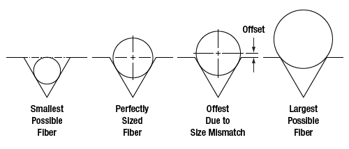
Each V-groove can accommodate a range of fiber sizes.
| Legend | ||
|---|---|---|
|
|
Best Fit | |
|
|
Second Best Fit: Try these options if the best fit does not incorporate your fiber sizes. | |
|
|
Third Best Fit: Try these options if the other two categories do not incorporate your fiber sizes. | |
Fiber Holder Insert Selection Chart
- First, select the bottom insert that matches your fiber size most closely.
Example: For a Ø800 µm fiber, the VHF750 insert is the closest match, since it is only 50 µm smaller. - On the chart below, look to the right of your chosen bottom insert. Select a compatible top insert based on the accepted diameter size range shown in each cell.
Example: For the Ø800 µm example fiber from step 1, the green cell is in the 750 µm groove column for the VHA05 top insert, which has two grooves. The numbers listed in the green cell indicate that this combination of inserts is good for fibers from 728 to 963 µm in diameter. Our Ø800 µm fiber is within this range, so this is a good choice. There are several other options as well that will accommodate a Ø800 µm fiber as well, but the green shading in the chart indicates that the 750 µm groove in the VHA05 provides the best fit. - The second line of numbers in each cell shows the range of offsets that can be expected for any given combination of top and bottom inserts. When selecting inserts for the right and left fiber holding blocks, try to minimize the offsets between the pairs of inserts on each side.
Example: If we choose a VHF750 bottom insert and the Ø750 µm groove in the VHA05 top insert, we can use fiber as small as 728 µm, in which case the center of the fiber would sit 23 µm below the surface of the bottom insert. We could also clamp a fiber as large as 963 µm, in which case the center of the fiber would sit 213 µm above the surface of the bottom insert. We could interpolate to find the offset experienced by our hypothetical 800 µm fiber, but it turns out that in a 60° V-groove, the offset is equal to the outer diameter difference. So in our example, that means that the center of our fiber is going to sit 50 µm above the bottom insert surface, since it is 50 µm larger than the fiber that the bottom insert was designed for (800 - 750 = 50). - Holding blocks designed for fibers less than Ø1000 µm have vacuum holes, designed to aid in aligning small fiber within the groove, while bottom inserts for fibers of Ø1000 µm or larger do not have these holes. The glass processors have a vacuum pump that provides a small holding force via these holes, keeping small fibers in place as the clamps are lowered. Inserts with vacuum holes are indicated by a superscript "d" in the table below.
| Top Insert Item # | VHA00a VHB00b |
VHA00a | VHA05c VHB05b |
VHA10c | VHA15c | VHA20c | VHA25 | VHA30 | |||||
|---|---|---|---|---|---|---|---|---|---|---|---|---|---|
| Accepted Diameter (Nominal) | ≤320 µm | 400 µm | 500 µm | 750 µm | 1000 µm | 1250 µm | 1500 µm | 1750 µm | 2000 µm | 2250 µm | 2500 µm | 3000 µm | |
| Bottom Insert Item # |
Accepted Diameter (Nominal) |
Min / Max Accepted Diameter (µm) Min / Max Fiber Offset (µm) |
|||||||||||
| VHF160d,e | 160 µm | 112 / 208 -49 / 48 |
- | - | - | - | - | - | - | - | - | - | - |
| VHF250d,e |
250 µm | 177 / 320 -73 / 69 |
275 / 323 23 / 74 |
- | - | - | - | - | - | - | - | - | - |
| VHF400d,e |
400 µm | 279 / 519 -122 / 119 |
377 / 517 -23 / 117 |
410 / 519 -9 / 119 |
- | - | - | - | - | - | - | - | - |
| VHF500d,e |
500 µm | 346 / 592 -153 / 93 |
447 / 647 -53 / 147 |
476 / 711 -24 / 211 |
560 / 795 61 / 296 |
- | - | - | - | - | - | - | - |
| VHF750d,e |
750 µm | 516 / 759 -234 / 9 |
617 / 970 -132 / 221 |
643 / 878 -107 / 128 |
728 / 963 -23 / 213 |
812 / 1047 62 / 297 |
- | - | - | - | - | - | - |
| VHE10c | 1000 µm | - | - | 773 / 1008 -172 / 63 |
858 / 1093 -88 / 147 |
943 / 1178 -3 / 232 |
1036 / 1271 90 / 325 |
- | - | - | - | - | - |
| 1250 µm | - | - | - | 1034 / 1269 -176 / 59 |
1119 / 1354 -91 / 144 |
1212 / 1447 2 / 237 |
1288 / 1523 78 / 313 |
- | - | - | - | - | |
| VHE15c | 1500 µm | - | - | - | - | 1280 / 1515 -172 / 63 |
1373 / 1608 -79 / 156 |
1449 / 1684 -2 / 233 |
1534 / 1769 82 / 314 |
- | - | - | - |
| 1750 µm | - | - | - | - | - | 1534 / 1770 -159 / 76 |
1611 / 1846 -83 / 152 |
1695 / 1930 2 / 237 |
1772 / 2007 78 / 313 |
- | - | - | |
| VHE20c | 2000 µm | - | - | - | - | - | - | 1787 / 2022 -171 / 64 |
1871 / 2106 -86 / 149 |
1947 / 2183 -10 / 225 |
2032 / 2267 74 / 309 |
- | - |
| 2250 µm | - | - | - | - | - | - | - | 2033 / 2268 -167 / 68 |
2109 / 2344 -91 / 144 |
2193 / 2429 -6 / 229 |
2278 / 2513 78 / 313 |
- | |
| VHE25 | 2500 µm | - | - | - | - | - | - | - | - | 2270 / 2505 -172 / 64 |
2355 / 2590 -87 / 148 |
2439 / 2675 -2 / 233 |
2609 / 2844 167 / 402 |
| VHE30 | 3000 µm | - | - | - | - | - | - | - | - | - | 2692 / 2944 -256 / -4 |
2777 / 3029 -171 / 81 |
2946 / 3198 -2 / 250 |
Fiber Holder Insert Assembly and Installation
After you select the correct fiber inserts for your nominal fiber diameter, the fiber inserts need to be installed into the fiber holding blocks, as shown in the video below to the left. Standard fiber inserts are meant to remain installed in a system when processing fibers of the same size, while fiber transfer inserts are used to move a fiber from one compatible Vytran machine to another between processing steps. Transfer inserts consist of a fiber holder bottom insert, fiber transfer clamp, and graphite V-groove that require assembly as shown in the video below to the right.
Introduction
To assist new or returning GPX users with operating their glass processors, we have created a series of tutorials aimed at teaching the basic skills needed to run this machine including hardware installation, software familiarization, filament setup, and processing fibers. To read the text in the videos, we strongly recommend viewing them at full screen, 1080p resolution. If you require assistance performing other operations using your GPX glass processor, please contact Tech Support.
| Quick Links | Setup and Nomenclature | Hardware Installation | Software Introduction | Filament Setup | Processing |
Setup and Nomenclature
To assist new or returning GPX glass processor users with operating their glass processors, we have created a series of tutorials aimed at teaching the basic skills needed to run this machine including lab bench setup, argon setup, and common nomenclature. To read the text in the videos, we strongly recommend viewing them at full screen, 1080p resolution. If you require assistance performing other operations using your GPX glass processor, please contact Tech Support.
Hardware Installation
The GPX series glass processors use an omega-shaped filament to heat glass components for splicing or tapering. Filaments are chosen based on the diameter of the fibers to be processed and what process will be performed. Once the appropriate filament is chosen, it must be installed by the user.
To accommodate a range of fiber diameters, top and bottom fiber holding inserts are chosen based on the size of fiber to be processed. Once chosen, the inserts can be installed to position fibers along the fiber line of the unit. While standard inserts remain mounted in the fiber holding blocks, transfer inserts can facilitate the movement of a fiber between Vytran devices, allowing users to perform multiple processes to a section of fiber without needing to realign the fiber end. This is thanks to the reference ball and matching surface present on the transfer inserts and fiber holding blocks, respectively. Transfer inserts are assemblies made from a fiber transfer clamp, special bottom insert, and a graphite v-groove.
Software Introductions
Many Vytran fiber processors, including the GPX glass processing workstation, use the FFS3 software package to control all parameters of the setup, fusion, and tapering. This software has a variety of tools and functions; the following videos will help familiarize users with the basic menus and toolbars commonly used in day-to-day operation.
Filament Setup
Once familiarized with the FFS3 software, users can set up the filament for processing glass. A newly installed filament must be centered along the fiber line to ensure even heating around glass components being processed. Once centered, brand new filaments must be burned in before use. The burn-in process consists of bringing the filament to a high temperature and back down to room temperature using a routine included in the software. This routine is performed six times with a one-minute cooldown between each execution. A new filament only needs to be burned in once.
The power required to heat a filament to the same temperature will vary over the life of the filament. To adjust for the filament's age, a normalization process can be carried out, which consists of heating two fiber tips and measuring the resulting rounding. Regular normalization of a filament ensures consistent performance over its life. At the end of its life, a filament can be refurbished by Vytran; contact Tech Support for more information on filament refurbishing.
Processing
Users should familiarize themselves with how to align fibers along the fiber line. Once comfortable aligning fibers, users can begin with splicing same-sized single mode or multimode fibers. Users who can successfully perform these operations will have a basic understanding of fiber processing with GPX systems, allowing them to approach more advanced or specialized techniques for their particular application. The GPX series of glass processors can perform splices and tapers on a variety of glass components. Our engineering staff can help design splicing programs in the FFS3 software to automate processing components for your specific application.
| Included Splice Files | ||
|---|---|---|
| Filament | FTAV2 (Graphite V2) | FTAV4 (Graphite V4) |
| Splice Files |
|
|
Each glass processor and splicer is shipped with a monitor and a PC pre-installed with our FFS3 software, which is used to operate each system. This software package allows users to control all parameters of the set-up, fusion, and tapering. Each step can be initiated by the user through the graphical user interface (GUI) or through one-button splice process files that run automated routines.
Common splicing and tapering routines, including those listed to the right, come preinstalled on the system. The GUI and splice library software enable users to create their own splice files for new processes or to customize existing files as necessary. Additionally, an add-on software package is available that includes application files for specialized applications that can be purchased separately below. Please contact Tech Sales for inquiries regarding your specific application.

Click to Enlarge
Figure 4. Multi-Stage Splicing Configuration
Click to Enlarge
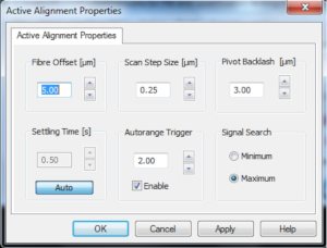
Figure 5. Active X-Y Alignment Scan Properties
Multi-Stage Splicing
For special applications, the software can run several splice steps in a sequence. Users can independently set the splice parameters for each step, as shown in Figure 4. Alternatively, multiple independent splice files from the user's library can be executed in order. The system will then perform a complex splicing function according to the sequence of the selected splice files.
Active Alignment
The active alignment method is typically used for fiber that has a high core eccentricity. In this case, standard imaging methods cannot always ensure proper alignment of the fiber cores. Instead, the cores are aligned using the output from an optical power meter as feedback to maximize the power transmission between the two fibers. This is done by scanning one fiber across the other with a given scan step size and taking a power meter reading at each position. At the end of the scan, the fiber is moved back to the position at which the optical power was either maximized or minimized. Parameters for this scan, such as step size and fiber offset position, can be set within the software to ensure accurate alignment, as shown in Figure 5.
Thorlabs' Vytran® Optical Fiber Glass Processors are versatile, fully integrated glass processing and fiber splicing platforms for fabricating splices, tapers, and custom terminations with high precision and low loss. Featuring a comprehensive applications library, these processes can be performed for many different fiber sizes and types. Examples of a few fiber splicing/processing applications are listed in the sections below and highlighted in the video to the right.
Click to Enlarge
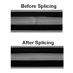
Two fibers with dissimilar cores before and after splicing. The dissimilar cores are clearly visible before the cores are thermally expanded.
Filament Fusion
Fusion Splicing is a process of joining two optical fibers end-to-end using heat. The goal is to fuse the two fibers together in such a way that light passing through the fibers is not scattered or reflected by the splice while ensuring that the splice and the region surrounding it should be almost as strong as the original fiber. The glass processors use a resistive graphite, iridium, or tungsten filament shaped like an upside-down omega to provide the heat necessary for fusion.
Once the two fibers to be spliced are aligned, the splice head is repositioned so that the filament is centered under the fiber ends. Power is then applied to the filament to raise its temperature to a level hot enough to fuse the fibers together, typically about 3000 °C. Because the filament would oxidize if it were brought to such a high temperature in air, high-purity argon gas is used to purge the splicing chamber of oxygen during the filament fusion process. In order to keep the fibers clean and improve splice strength, the purging gas (not available from Thorlabs) is set to flow over the fibers at a high rate during the fusion process.
Mode Adapters and NA Converters
In many applications, large-mode-area gain fibers may need to be coupled to fibers with a non-matching mode field diameter or NA. Glass processors can help optimize coupling between dissimilar fibers by altering the mode field diameter or NA of one fiber to match the other. This is accomplished by applying heat prior to splicing and/or to physically taper the fibers to change the core diameter. In the example shown to the right, two fibers (single mode fiber and Ø20 µm large-mode-area fiber) have dissimilar core sizes. In the lower image, the small cored fiber has been thermally expanded by diffusing the core dopants and then spliced together.
Fiber Processing Applications

Click to Enlarge
Ø20 µm core, Ø400 µm cladding large-mode-area (LMA) fiber tapered to Ø125 µm cladding.
Tapering and Drawing
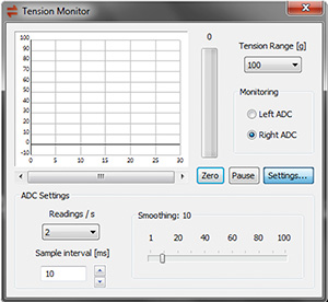
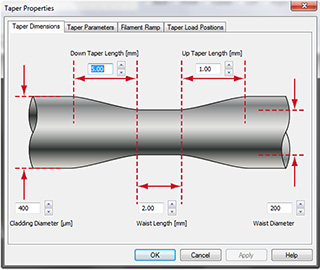
All Vytran glass processor configurations are capable of tapering (altering the cross-sectional diameter) or drawing out (increasing the length) of a fiber. This is accomplished by using the filament furnace to heat the fiber to its softening point and then applying a tensile force to elongate the fiber, reducing the cross section of the fiber. The fiber holders provide up to 180 mm of z-axis travel, enabling the fabrication of long tapers up to 150 mm in length. This process can be programmed through the GUI by entering the physical characteristics of the desired taper into a taper interface menu (see the Software tab for details). The software GUI also includes a tension monitor and control function, which can accurately monitor drawing conditions during tapering.
Fiber Terminations
These glass processing systems, which have an integrated platform that combines precise fiber positioning, control over the filament fusion process, and long tapering/drawing lengths, are ideal for adding or fabricating complex terminations to the ends of bare fibers. Examples of developed terminations include ball lenses, fiber catheters, and fiber probes.
End caps are large-core-diameter, short-length fibers used to diffuse the beam intensity of high-power fibers to prevent damage to fiber end faces. Glass processors are well suited for fusing large-core-silica end caps to the ends of power beam delivery fibers. We recommend using an LDC401 or LDC401A Fiber Cleaver to fabricate end caps with precise lengths.
Couplers and Combiners
Glass processors can fuse fibers side-by-side or into bundle configurations; this process is critical for fabricating fused fiber couplers and pump or output combiners. Through precise control of heating and tapering conditions and using multi-fiber holding block inserts, the operator is able to develop application-specific coupler and combiner solutions that feature very low loss.

Click to Enlarge
Two single mode fibers tapered and fused together for 50/50 coupling in a glass processor. Spacing between the fiber cores is approximately 15 to 20 µm.
 Product DemonstrationsThorlabs has demonstration facilitates for the Vytran® fiber glass processing systems offered on this page within our Morganville, New Jersey; Shanghai, China; Exeter, Devonshire; and Bergkirchen, Germany offices. We invite you to schedule a visit to see these products in operation and to discuss the various options with a fiber processing specialist. Please schedule a demonstration at one of our locations below by contacting technical support. We welcome the opportunity for personal interaction during your visit! Thorlabs GmbH
|
| Posted Comments: | |
user
(posted 2019-07-03 11:15:56.527) I want to the drawing with the size. YLohia
(posted 2019-07-03 04:54:27.0) Hello, thank you for contacting Thorlabs. I have reached out to you directly with the drawing of the VHA00. ashiq.asamad99
(posted 2018-01-12 05:53:56.237) Sir,
Can you please mention which type of motor is used in the device for rotating the fiber. And also i want to know,whether both end fibers are rotated or only one is rotating for aligning the fiber. tfrisch
(posted 2018-03-20 05:04:03.0) Hello, thank you for contacting Thorlabs. Though the design and components of these glass processing workstations are considered proprietary, I can reach out to you to discuss the specs of the motor as they relate to system performance. Furthermore, both the left and right fiber can be rotated independently. user
(posted 2016-01-19 14:27:44.2) It would be very useful if you offered preshaped fiber endcap blanks. Could be 2.54mm diameter cylindrical pieces with 8deg flat polish (AR coated option) on one end and conical taper for splicing to 250+um diameter fiber. It would make the GPX3600 more interesting if such an endcap solution was offered. besembeson
(posted 2016-01-20 08:26:59.0) Response from Bweh at Thorlabs USA: Thank you for your input and feedback. While we do not currently offer components such as these for our systems, it may indeed be something we consider in the near future. Our recent acquisition by Thorlabs will see us growing these possibilities going forward, and it is valuable feedback such as this that will drive the development. Thank you again, we truly value your input. |
| Vytran® Optical Fiber Glass Processor Selection Guide | |||||||
|---|---|---|---|---|---|---|---|
| Item # | GPX3400 | GPX3600 | GPX3800 | GPX3850 | GPX3900 | GPX4000LZ | |
| Splicing Fiber Cladding Diameter | 80 µm to 250 µm | ||||||
| 250 µm to 1.25 mm | |||||||
| 1.25 mm to 1.7 mm | - | - | - | ||||
| 1.7 mm to 2 mm | - | - | - | - | - | ||
| End Cap Fiber Diameter | 250 µm to 2 mm | - | - | - | - | - | |
| 250 µm to 5 mm | - | - | - | - | - | ||
| Fiber Type | Multimode | ||||||
| Single Mode | |||||||
| Double Clad | |||||||
| Polarization Maintaining | |||||||
| Soft Glass | - | - | - | - | - | ||
| Automated Measurement and Alignment | |||||||
| End-View Illumination and Imaginge | |||||||
| Tension Monitor and Control System | |||||||
| Integrated Fiber Cleaver | - | - | - | ||||
| Real-Time Hot Image Monitoring | - | - | |||||
| Liquid Cooling System | Optional Add-On | Optional Add-On | Optional Add-On | Optional Add-On | |||
| Fused Taper Software Enhancement and Handling Fixtures | Optional Add-On | - | |||||
| Fiber Combiner Loading Fixture | Optional Add-On | - | |||||

Components Included
- Glass Processor Workstation
- FTAV4 Graphite Filament Assembly (Ø125 µm - Ø600 µm Cladding) Pre-Installed (Additional Filaments Sold Below)
- Computer with Monitor, Keyboard, and Mouse
- Software Interface with Example Splice Files
- Vacuum Pump for Bottom Fiber Inserts
- Power Supply (See Specs Tab for Details)
- Regulator for Argon Gas Tank with CGA-580 and DIN 477 Number 6 Connectors
- 1/8" PTFE Tube for Argon Gas
- USB A to B Communication Cable
- USB 3.0 A to Micro B Camera Cable
- Tool Kit with Hex Keys for Filament/Insert Replacement
- Liquid Cooling System (GPX3600 Only)
Required Purchases
- Fiber Holder Top Inserts (Two Required)
- Fiber Holder Bottom Inserts (Two Required for Single Fiber Processing)
- Transfer Clamp and Graphite V-Grooves (Required for Transfer Inserts)
- >99.999% Purity Argon Gas Tank (Not Available from Thorlabs)
Optional Purchases
- Multi-Fiber Holder Bottom Inserts (Two Required for Making Couplers or Combiners)
- Fluorine-Doped Capillary Tubes (For Making Specialty Couplers or Combiners)
- Additional Filament Assemblies
- Liquid Cooling System (Optional Add-On for GPX3400)
- Fiber Taper Software Add-On and Handling Fixtures
- Fiber Combiner Loading Fixture
- Ultrasonic Cleaner
- Mountable Gooseneck Light
- Replacement SS2SN013 Setscrews for Fiber Holding Blocks
- Includes Glass Processor Workstation and Computer with Control Software
- Splice/Taper Optical Fibers Up to Ø1.25 mm (GPX3400) or Ø1.7 mm (GPX3600)
- Ideal for Single Mode, Multimode, Polarization-Maintaining, and Specialty Fibers
- Automatic XY and Rotational Alignment
- Fiber Z-Axis Travel of 180 mm
These Vytran Glass Processor Workstations feature automatic XY and rotational alignment of the fiber and are especially designed for processing polarization-maintaining fibers as well as specialty fibers with microstructured cores. The GPX3400 and GPX3600 can splice fibers with outer diameters up to 1.25 mm or 1.7 mm, respectively.
The precision fiber handlers can position a fiber in XY with a resolution of 0.25 µm and rotate a fiber up to 190° with a resolution of 0.02°. The included fiber holders can translate up to 180 mm along the fiber axis, allowing the filament to heat large portions of the input fiber(s). This extended heating range is ideal for many applications including thermally diffusing core dopants to achieve low-loss splices between highly dissimilar fibers or for fabricating long adiabatic fiber tapers. The fiber holding blocks can also pull vacuum through fiber holder inserts with vacuum holes to help secure the fiber within the insert.
The workstation includes the fiber holders, furnace assembly, CCD camera for imaging, PC and monitor pre-installed with the control software, and mirror tower for side- and end-view imaging. Each processor workstation is fitted with a high-purity PTFE gas line and a gas regulator equipped with a CGA-580 output port; a DIN 477 Number 6 output port connector is also included. An FTAV4 Graphite Filament Assembly (for Ø125 µm - Ø600 µm Cladding) comes pre-installed in the system; additional graphite, iridium, or tungsten filaments are sold separately below. Top and bottom inserts for the fiber holders, both of which are required to operate the glass processor workstation, can also be purchased separately below. Nylon-tipped setscrews are used to secure the inserts in the fiber holding blocks; replacement 2-56, 1/8" long SS2SN013 setscrews are available in packs of 10.
Installation and training by one of our application engineers is recommended for this system; please contact Tech Support for more details.

| Item # | Filament Material |
Cladding Diameter (Min/Max) |
Applicationa |
|---|---|---|---|
| FTAV2 | Graphite | 80 µm / 250 µm | Splice |
| FTAV4 | 125 µm / 600 µm | ||
| FTAV5 | 250 µm / 1000 µm | ||
| FTAV6 | 400 µm / 1300 µm | ||
| FTAT3 | 250 µm / 1500 µm | Taper | |
| FTAT4 | 400 µm / 1800 µm | ||
| FRAV1 | Iridium | ≤200 µm | Splice |
| FRAV3 | ≤400 µm | ||
| FRAV5 | 250 µm / 1050 µm | ||
| FWAV1 | Tungsten | ≤200 µm | Spliceb |
- Filament Assemblies for Automated Glass Processors (One FTAV4 Graphite Filament Pre-Installed in System)
- Optimized for Splicing, Tapering, or Lensed Tip Applications (See Table to the Right for Details)
- Assembly Includes Filament Element and Protective Shroud
Filament assemblies contain a graphite, iridium, or tungsten omega-shaped resistive heater element encased within a protective shroud. The filaments sold here are compatible with the automated glass processors; those indicated in the table to the right as splice filaments are also compatible with the LFS4100 Splicing System.
Filaments for Splicing or Tapering
Graphite filaments are capable of achieving the high temperatures necessary for splicing or tapering large-diameter fibers while outgassing less than filaments made from other metals. Iridium filaments heat fibers at lower temperatures than graphite filaments, making these ideal for working with soft glass fibers. Tungsten filaments offer narrower heat zones and reach temperature very quickly, making them ideal for splicing highly doped fibers and structured fibers where long splice duration could cause significant diffusion or collapse. Although the heating time of a filament is approximately 40 minutes, this can vary depending on a number of factors including argon quality, splice/taper duration, and fiber glass quality.
These filaments are optimized for splicing or tapering applications; this is not restrictive, however, as splice filaments can be used for tapering. Splice filaments have an opening in the top of the assembly body, while tapering filaments are closed off at the top to minimize exposure to contaminants.
Identification & Maintenance
One FTAV4 filament comes pre-installed in the system. Different filament bodies are distinguished by the version number (e.g., V4, V6, T3) engraved on the assembly body. Before a new filament can be used in a system, it must be burned in. During the burn-in process, the filament is cycled between its operating temperature and room temperature several times. This stabilizes the thermal properties of the filament so that it produces a more consistent power output and heating performance when current is passed through it. This procedure only needs to be performed once, after which the filament will only need regular normalization. Visit the Tutorial Videos tab above to see videos on how to perform filament maintenance and simple splices. If filament performance begins to degrade, filament refurbishments can be ordered by contacting Tech Support.

| Item # | Side 1 Accepted Diameter (Min/Max) |
Side 2 Accepted Diameter (Min/Max) |
|---|---|---|
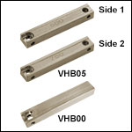
| VHB00a | 57 µm / 759 µmb | N/A |
| VHB05a | 410 µm / 1008 µm | 560 µm / 1269 µm |
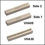
| VHA00 | 57 µm / 759 µmb | 275 µm / 970 µm |
| VHA05 | 410 µm / 1008 µm | 560 µm / 1269 µm |
| VHA10 | 812 µm / 1515 µm | 1036 µm / 1770 µm |
| VHA15 | 1288 µm / 2022 µm | 1534 µm / 2268 µm |
| VHA20 | 1772 µm / 2505 µm | 2032 µm / 2944 µm |
| VHA25 | 2278 µm / 3029 µm | N/A |
| VHA30 | 2609 µm / 3198 µm | N/A |
- Top Inserts for Fiber Holding Blocks
- Accepts Fiber Outer Diameter (Cladding/Coating) from 57 µm to 3.198 mm (See the Fiber Holder Inserts Tab for Information on Choosing Inserts)
- Single-Sided and Dual-Sided Inserts Available (See Table to the Right for Details)
- VHBxx End-View Illumination Insert Available for Automated Glass Processors and Splicing Systems
- Compatible with Automated Glass Processors, LDC401 Series Fiber Cleavers, FPS301 Stripping and Cleaning Station, and LFS4100 Splicing System
Fiber Holder Inserts, which consist of one top insert and either a bottom or transfer insert, are placed in the fiber holding blocks of the optical glass processor to secure the fiber during splicing or tapering. The inserts clamp the cladding, buffer, or coating of the fiber and can accommodate outer diameters of up to 3.198 mm. The Fiber Holder Inserts tab above includes information to aid in selecting and installing the correct combinations of top and bottom inserts to accommodate different fiber diameters.
Two types of top inserts are compatible with the automated glass processors. The VHA standard top inserts come in single-sided and dual-sided versions. These standard inserts can also be used in the LDC401 Series of Fiber Cleavers, FPS301 Stripping and Cleaning Station, and LFS4100 Splicing System. The VHB00 and VHB05 top inserts (shown to the left) feature an indent for LED illumination from the automated glass processor workstations and are necessary for end-view imaging and alignment of the cores of polarization-maintaining and microstructured specialty fibers.

| Item # | Type | Side 1 Accepted Diameter (Min/Max) |
Side 2 Accepted Diameter (Min/Max) |
Vacuum Holes |
|---|---|---|---|---|
| VHF160 | Transfer | 112 µm / 208 µm | N/A | Yes |
| VHF250 | 177 µm / 320 µm | N/A | Yes | |
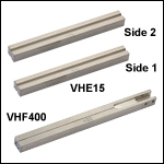
| VHF400 | 279 µm / 519 µm | N/A | Yes | |
| VHF500 | 346 µm / 795 µm | N/A | Yes | |
| VHF750 | 516 µm / 1047 µm | N/A | Yes | |
| VHE10 | Standard | 773 µm / 1271 µm | 1034 µm / 1523 µm | No |
| VHE15 | 1280 µm / 1769 µm | 1534 µm / 2007 µm | No | |
| VHE20 | 1787 µm / 2267 µm | 2033 µm / 2513 µm | No | |
| VHE25 | 2270 µm / 2844 µm | N/A | No | |
| VHE30 | 2692 µm / 3198 µm | N/A | No |
- Bottom Fiber Inserts with V-Grooves for Fiber Holding Blocks
- Compatible with Cladding/Coating Diameters from 112 µm to 3.198 mm (See the Fiber Holder Inserts Tab for Information on Choosing Standard or Transfer Inserts)
- Transfer Inserts for Moving Fiber Between Vytran Systems
- Inserts with Vacuum Holes for Aligning Smaller Fibers (<Ø1047 µm) in V-Groove
Fiber Holder Inserts, which consist of one top insert and a bottom insert, are placed in the fiber holding blocks of the optical glass processor to secure the fiber during splicing or tapering. Bottom inserts are magnetically held within the fiber holding blocks of the glass processors and other compatible systems. The V-groove machined into the bottom inserts ensures the fiber is centered within the fiber holder; inserts with different V-groove sizes are available. Vacuum holes at the bottom of the transfer inserts are used for holding and aligning small fibers within the V-groove. The Fiber Holder Inserts tab above includes information to aid in selecting and installing the correct combinations of top and bottom inserts to accommodate different fiber diameters.
Three types of bottom inserts are compatible with the glass processors: transfer bottom inserts, standard bottom inserts, and multi-fiber bottom inserts (sold further below). Transfer bottom inserts (indicated with item #s starting with VHF) allow for a single fiber to be transferred between the LDC401 Series of Fiber Cleavers, FPS301 Stripping and Cleaning Station, and LFS4100 Splicing System with minimal loss of alignment. For example, a fiber can be placed in a transfer insert and cleaved using the LDC401 cleaver, then the entire transfer insert can be placed in the LFS4100 Splicing System for splicing. This process works because the transfer inserts are precisely located within each Vytran system, and the VHT1 Magnetic Lid (sold directly below) prevents axial movement of the fiber during transport. Transfer inserts are equipped with vacuum holes that provide a small suction force to hold the fiber in place. All of these transfer inserts require the VHT1 Transfer Clamp (sold below); transfer inserts for fiber outer diameters ≤550 µm also require a Graphite V-Groove (sold below).
Standard Fiber Holder Bottom Inserts (indicated by item #s starting with VHE) can be used with large-diameter fibers. These inserts come in single-sided and dual-sided versions. The standard bottom inserts can also be used in the LDC401 Series of Fiber Cleavers, FPS301 Stripping and Cleaning Station, and LFS4100 Splicing System. Unlike transfer inserts, alignment of the fibers will not be maintained when these inserts are transferred between systems.

| Item # | Accepted Diametera (Min / Max) |
Groove Length |
|---|---|---|
| VHG125 | 80 µm / 125 µm | 0.313" |
| VHG125L | 80 µm / 125 µm | 0.594" |
| VHG200 | 150 µm / 200 µm | 0.313" |
| VHG250 | 200 µm / 250 µm | 0.313" |
| VHG250L | 200 µm / 250 µm | 0.594" |
| VHG300 | 250 µm / 300 µm | 0.313" |
| VHG350 | 300 µm / 350 µm | 0.313" |
| VHG400 | 350 µm / 400 µm | 0.313" |
| VHG450 | 400 µm / 450 µm | 0.313" |
| VHG500 | 450 µm / 500 µm | 0.313" |
| VHG500L | 450 µm / 500 µm | 0.594" |
| VHG550 | 500 µm / 550 µm | 0.313" |
- Clamp and Graphite V-Grooves Used with Transfer Bottom Inserts to Move Fiber Between Vytran Systems
- One VHT1 Transfer Clamp Required with Each Transfer Bottom Insert
- Transfer Clamps are Compatible with GPX Fiber Processors, LDC401 Series and LDC405B Fiber Cleavers, the FPS301 Fiber Preparation Station, and the LFS4100 Fusion Splicer
- Graphite V-Grooves for Supporting Fibers ≤Ø550 µm
- V-Grooves Accept Diameters from 80 µm to 550 µm
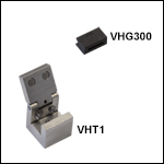
These Transfer Clamps and V-Grooves are used with the VHF Transfer Bottom Inserts sold directly above to move a single fiber between various Vytran systems with minimal loss of alignment. For example, a fiber can be placed in a transfer insert and cleaved using the LDC401 Fiber Cleaver. Then, the entire transfer insert and fiber can be moved to a glass processor for splicing.
The VHT1 clamp secures transfer inserts with a magnetic lid that prevents axial movement of the fiber and can be used to hold the insert during transport without touching the fiber itself. For fibers with diameters ≤550 µm, a graphite V-groove is available to support the fiber when splicing (please see the size table to the right for more information). To provide extended support along the length of the fiber and reduce the amount of overhang during processing, we also offer 0.594" long V-grooves (Item #'s VHG125L, VHG250L, and VHG500L). The graphite V-grooves are secured by tightening two setscrews on the transfer insert. For information on how to assemble transfer inserts, see the Fiber Holder Inserts tab.

| Item # | Type (Click for Drawing) |
Accepted Diameters | Recommended Top Inserta |
|---|---|---|---|
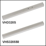
| VHD125S | Side-by-Side | 125 µm / 125 µm | VHA00 |
| VHD250S | Side-by-Side | 250 µm / 250 µm | |
| VHD320S | Side-by-Side | 320 µm / 320 µm | |
| VHD250V | Double-V Slot | 250 µm / 250 µm | |
| VHD320V | Double-V Slot | 320 µm / 320 µm | |
| VHD320P | Double-V Slot w/ Pins | 320 µm / 320 µm | |
| VHS250250 | Triple-V Slot | 250 µm / 250 µm / 250 µm | |
| VHS250400 | Triple-V Slot | 250 µm / 400 µm / 250 µm | |
| VHS250500 | Triple-V Slot | 250 µm / 500 µm / 250 µm | |
| VHS300350 | Triple-V Slot | 300 µm / 350 µm / 300 µm | |
| VHS320400 | Triple-V Slot | 300 µm / 400 µm / 300 µm | |
| VHS320550 | Triple-V Slot | 320 µm / 550 µm / 320 µm | VHA05 |
Click to Enlarge
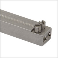
The VHD320P features adjustment pins that are used to bring two fibers into very close proximity for splicing.
- Bottom Inserts with Grooves for Holding Multiple Fibers
- Used When Creating Fused Couplers or Combiners
- Vacuum Holes for Aligning Fibers in V-Grooves or Slots
- Multiple Insert Types Available (See Table for Options)
Multi-Fiber Inserts are designed for applications requiring two or three fibers to be tapered and fused together, such as when making wavelength division multiplexers, fused fiber couplers, or power combiners.
Side-by-side inserts have a U-shaped groove for holding two fibers tightly together in parallel. Double-V-slot inserts feature two parallel V-grooves on the same side of the insert that each hold a single fiber. The VHD320P insert additionally features offset adjustment pins that are used to bring the two fibers in close contact during splicing (see photo to the left). Triple-V-slot inserts have a V-groove in the middle and two V-grooves adjacent on both sides that allow a signal fiber to be fused with two pump fibers.
These bottom inserts are magnetically held within the fiber holding blocks of the glass processors and other compatible systems. The grooves machined into the inserts ensure the fiber is centered within the fiber holder. Vacuum holes at the bottom of the transfer inserts are used for holding and aligning small fibers within the V-groove. Recommended top inserts for each multi-fiber insert are indicated in the table to the right. Alignment of the fibers will not be maintained when these inserts are transferred between systems.

Click to Enlarge
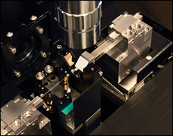
An example application shows the GPXM45 Insert being used in Top View to inspect the end face of an endcapped fiber on the GLZ4001EC CO2 Laser End-Cap Splicer Workstation.
- For Inspection of Fiber End Faces and Alignment of Fiber Components
- 10 mm Square 45° Inspection Mirror
- Compatible with the LFS4100 Splicer, the GLZ4001EC CO2 Laser End-Cap Splicer Workstation, and GPX Series Fiber Processors.
The GPXM45 Insert with 45° Mirror provides an additional method for inspection of fiber end faces and alignment of fiber components. A fiber holding block on any of the compatible Vytran systems listed above secures the mirror insert in the same way as a fiber holder bottom insert. On the GPX series fiber processors and the LFS4100 splicer, which have smaller end-view mirrors, this insert provides a larger, 10 mm square mirror as an additional inspection option. Additionally, this mirror can be used outside the Vytran systems as a convenient inspection tool on an optical bench or a microscope.


Click to Enlarge
End-view image of 3:1 combiner made using a capillary tube.
| Item # | Inner Diameter | Outer Diameter | Length |
|---|---|---|---|
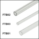
| FTB02 | 750 ± 100 µm | 1500 ± 100 µm | 170.0 ± 3 mm |
| FTB03 | 800 ± 40 µm | 1100 ± 55 µm | |
| FTB01 | 1200 ± 60 µm | 1450 ± 75 µm |
- Capillary Tube for Manufacturing Fiber Combiners
- Three Diameter Combinations Available, 170 mm Long
- Compatible with GPX3400, GPX3600, GPX3800, GPX3850, and GPX3900 Processors
Fluorine-doped silica capillary tubes are ideal for the manufacture of high-power fiber laser combiners and other specialty applications. During this process, the fibers that will be joined are inserted into the capillary tube, then the tube is fused and tapered down into a solid glass element. With a core consisting of the fused fibers and a cladding formed by the low-index capillary tube, the tapered element acts as a multimode waveguide, with the capillary tube serving to contain the light in the combiner.
Please make sure to use gloves when handling these fluorine-doped tubes.

| Liquid Cooling System Specifications | |
|---|---|
| Cooling Capacity | 590 Wa |
| Coolant Pump Flow Rate | 10 Speed Levels up to 4 L/min |
| Reservoir Capacity | 157 mL (5.3 fl-oz) |
| Radiator | Aluminum; 2 x 120 mm Fans |
| Power Consumption | 20 W (Max) |
| Power Supply | 12 VDC (via Molex Connector) 110/120 VAC with Power Adapter |
| Weight | 8.00 lbs (3.63 kg) |
- Included with GPX3600 Glass Processor Workstation
- Optional Add-On for GPX3400 Glass Processor Workstation
- Liquid Cooling System for Vytran Glass Processors and Splicing Systems
- Prevents Furnace Overheating During Extended Heating Operation (e.g., Tapering)
- Includes 700 mL (24 fl oz) of High-Performance Liquid Coolant
The GPXWCS Liquid Cooling System is an optional add-on for our Vytran Glass Processors that helps keep the furnace assembly cooled during extended heating operations. It is highly recommended for customers interested in fiber tapering, mode adapter, or fiber termination applications. This cooling system is also compatible with the LFS4100 Splicing System but is not necessary for standard splicing processes.
The GPXWCS has a 157 mL reservoir to cycle high-performance liquid coolant (700 mL bottle of coolant included) at flow rates of up to 4 L/min with a cooling capacity of 590 W at 25 °C ambient temperature; click here for a MSDS safety sheet. Tubing and fittings for connecting to a Vytran Glass Processor are included. The cooling system can be powered either through a 12 VDC Molex Connector (via the included computer slot adapter) or externally using the included 110/120 VAC power adapter.

Click to Enlarge
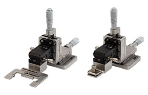
Comparison of Adjustable Gripper (Left) and Removable Taper Holder (Right) Fixtures
| Fused Taper Software and Handling Fixtures | |||
|---|---|---|---|
| Item # | FBT Software |
Adjustable Gripper |
Removable Taper Holder |
| GPXFBT-SFT |  |
- | - |
| GPXFBT-FXTA | - |  |
- |
| GPXFBT-FXTB | - | - |  |
| GPXFBT-KITA |  |
 |
- |
| GPXFBT-KITB |  |
- |  |
- Software Enhancement Enabling Active Fused Biconic Taper (FBT) Processing
- Fixture with Adjustable Fiber Gripper for Transporting Fiber Tapers and Couplers to a Packaging Station
- Fixture with Removable Fiber Holder for In Situ Packaging of Fiber Tapers and Couplers
- Applications:
- Microscale and Nanoscale Fiber Tapers
- Fused Fiber Couplers and Wavelength Division Multiplexers (WDMs)
- Tapered Fiber Coupling Microresonator and Whispering Gallery Mode Structures
- Cavity Optomechanics
- Biosensing and Microparticle Sensing
These optional add-ons for the Vytran Glass Processors are designed to aid microtaper and fused fiber coupler processing. The software and fixture add-ons can be purchased separately or together in a kit. The GPXFBT-SFT software package enables finer control over heating and fiber pulling parameters during active FBT processes, resulting in improved yields and high repeatability between runs.
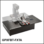
Two fixture add-ons are also available. The GPXFBT-FXTA Adjustable Taper Fiber Gripper fixture provides a stable base for your specific length component, allowing transfer to a packaging station. The fiber gripper can be adjusted to accommodate taper lengths from 0 - 3.15" (0 - 80 mm). The GPXFBT-FXTB Removable Taper Holder Fiber Fixture option acts as a pick-up and removal apparatus for the user to safely and securely transport the fabricated taper or coupler for secondary processing or in situ packaging. The stages included with these fixtures have an X-axis and Y-axis travel of 1" (25.4 mm) and a roll and yaw adjustment of ±2.5° and ±5°, respectively.

| Combiner Fixture Specifications | |
|---|---|
| Degrees of Freedom | Five (X, Y, Z, Pitch, Yaw) |
| Y-Axis Travel (Coarse) | 300 mm |
| X-Axis Travela | 0.44" (11.2 mm) |
| Z-Axis Travela | 0.20" (5.1 mm) |
| Platform Flatness | ±0.005" |
| Platform Thickness | 6 mm |
| Platform Material | Mic-6 Aluminum |
| Bottom Insert (One Required) |
VHS, VHD, VHE, or VHF Series |
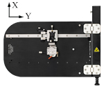
Click to Enlarge
The fiber holding block assembly translates along a rail for Y-axis positioning.
- Supports the Positioning of Fiber Bundles for Combiner Fabrication
- Five Degrees of Freedom: X, Y, Z, Pitch, Yaw
- 300 mm Coarse Travel Along Fiber Feed Axis
- Working Platform Folds Up 90° for Fiber Bundle Grouping
- Required Bottom Insert Sold Separately
- Contact Tech Support for Right Side Mounting Variant
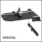
The GPXCFXL Fiber Combiner Loading Fixture is an optional add-on for our GPX3000 Series Glass Processors that provides support and five-axis positioning of fiber bundles during manufacture of fiber combiners. The multi-axis assembly enables direct insertion of fiber bundles into fragile tapered capillary tubes. This reduces the risk of tube breakage by allowing controlled bundle insertion while the capillary tube is still in the glass processing station.
The bundle is placed in the bottom insert (sold separately above), which is mounted in the assembly's fiber holding block. XZ translation is provided by the integrated T12XZ stage, while the support assembly is attached to a rail for travel in the fiber feed direction. To aid with bundle alignment, coarse pitch and yaw adjustments are achieved through a lockable ball pivot mechanism; note that this mechanism also allows off-axis roll that is coupled with translation. The stage's travel along the rail (Y-axis) is also lockable.
The fixture mounts to the left side of processors and supports a wide variety of inserts to suit individual needs. The working platform features a double hinge to ensure a gapless working surface and folds up 90° with an air spring support and a pin lock at the vertical and horizontal positions. Please contact Tech Support to request a variant for mounting on the right side of a processor.


Click to Enlarge
USC2 Ultrasonic Cleaner and USC2NVT Nest for Vytran Transfer Bottom Inserts
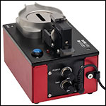
Click to Enlarge
The cleaning intensity and duration controls are located on the rear of the cleaner.
| USC2 Ultrasonic Cleaner Specifications | |
|---|---|
| Supported Fiber Diametera | 125 - 600 µm |
| Tank Capacity | 100 mL |
| Tank Dimensions | Ø1.7" x 2.8" Deep (Ø43 mm x 71 mm Deep) |
| Cleaning Duration (Max Setting) |
>1 Minute |
| Peak Output Frequency | 75.2 - 76.4 kHz |
| Transducer Power (Max) | 6 W |
| Operating Power | 36 W |
| Operating Current | 1.5 A |
| Input Voltageb | 100 - 240 VAC @ 47 - 63 Hz |
| Overall Dimensionsa |
6.95" x 4.78" x 4.13" (176.5 mm x 121.5 mm x 104.8 mm) |
| Mass | 1.28 kg (2.82 lbs) |
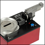
Click for Details The USC2NVT Nest adds support for Vytran transfer bottom inserts.
- Easy-to-Adjust Immersion Depth, Cleaning Duration, and Power Level
- Bare Fiber Nest with Magnetic Clamp Included
- Nest for Vytran Transfer Bottom Inserts Sold Separately (Item # USC2NVT)
- Compatible Solvents: Acetone or Isopropanol (Isopropyl Alcohol)
- Spout for Easy Fluid Disposal; Slotted Shield for Reduced Solvent Evaporation
Thorlabs' Vytran® USC2 Ultrasonic Fiber Cleaner is designed for volume processing of bare fiber. Adjustment knobs for cleaning intensity and cleaning duration allow the user to easily set repeatable cleaning parameters. The dunking jig offers adjustable immersion depth and is compatible with interchangeable fiber holder nests (each sold separately). A red LED indicates when the cleaning cycle is active. The 100 mL solvent tank is only suitable for use with acetone or isopropyl alcohol.
Tilting the dunking jig submerges the fiber in the tank and initiates the ultrasonic cleaning process. The ultrasonic agitation ceases after the chosen cleaning duration. The height of the fiber holder above the solvent tank can be changed over a 0.5" (12.7 mm) range using the knurled adjuster on the side of the dunking jig, visible in the photo above.
The knurled adjuster can also be reversed to disengage the bare fiber nest and switch it out for another fiber holder nest. Each cleaner is shipped with a bare fiber nest installed in the dunking jig. The USC2NVT Nest (sold separately) is designed for use with Vytran transfer bottom inserts. Accessories are available for the Vytran fiber nest to support a wider range of usage scenarios, including a clamp for standard bottom inserts and spacers for recessing inserts farther from the solvent tank. We also offer nests for Fujikura® and Fitel® fiber holders (each sold separately). Please see the complete product presentation for more information.

| GPXL1 Gooseneck Light Specifications | |
|---|---|
| Lamp Electrical Power | 1 W |
| Color Rendering Index (CRI) | 80 |
| Lamp Lifetime | 30 000 h |
| Lamp Luminous Flux | 100 lm |
| Lamp Luminous Efficiency | 80 lm/W |
| Operating Temperature | -25 to 45 °C |
| Light Color | Neutral White |
| Input Voltage | 12 VDC |
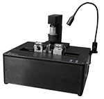
Click to Enlarge
The GPXL1 can be attached on either the right or left side of the glass processor workstation
- Attaches to Either Side of Workstation
- Illuminate Fiber Ends or Light General Work Area
- 12 VDC Power Supply (Sold Separately) Includes Region-Specific Power Cord
The GPXL1 Gooseneck Light is a lamp that can be used to couple light into a fiber combiner for end-view illumination or for general lighting of the workstation during alignment. The lamp features an on/off switch and a dimmer knob to control brightness. The flexible neck allows the lamp head to be easily positioned near a fiber or furnace.
Mount the GPXL1 on either side of the workstation using the mounting holes on the workstation (as seen in the image to the right). Two 10-32 mounting screws and a 5/32" hex key are included.
Users must also purchase a GPXL1PS 12 VDC Power Supply along with the GPXL1. The power supply includes a region-specific power cord which must be used with an 85 - 265 VAC, 47 - 63 Hz power source.
 Products Home





 Zoom
Zoom

 Glass Processors