 Products Home / Optical Elements / Optical Mirrors / Plano Metallic Mirrors / Protected Silver Mirrors
Protected Silver Mirrors
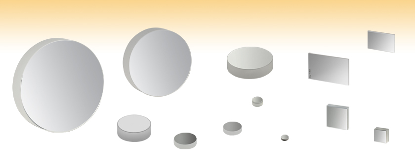
- High Reflectance in Visible and NIR Regions
- Round, Square, and Rectangular Mirrors Available
PF40-03-P01
Ø4"
PF10-03-P01
Ø1"
PF30-03-P01
Ø3"
PF07-03-P01
Ø19 mm
PF03-03-P01
Ø7 mm
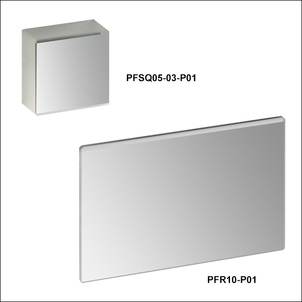
PFSQ05-03-P01
1/2" x 1/2"
PF05-03-P01
Ø1/2"
PFSQ10-03-P01
1" x 1"
PF20-03-P01
Ø2"
PFR10-P01
25 mm x 36 mm
PFR14-P02
35 mm x 52 mm
PF15-03-P01
Ø1.5"


Please Wait
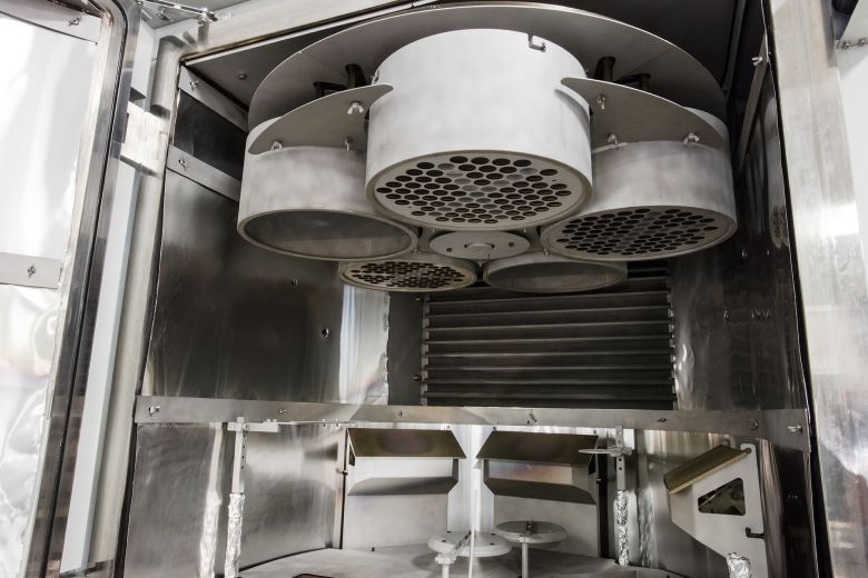
Click to Enlarge
A Number of Metallic Mirror Blanks Mounted in Planets at the Top of One of Our Electron Beam Deposition Coating Chambers
Features
- Silver Coating Highly Reflects in Visible and NIR Range
- Ravg > 97% for 450 nm - 2 µm;
- Ravg > 95% for 2 - 20 µm
- Protective SiO2 Overcoat Protects from Oxidation
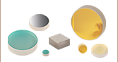
- Available Round, Square, Rectangular, or in Packages of 10 Rounds
Silver coated mirrors offer the highest reflectance in the visible-NIR spectrum of any metallic mirror, while also offering high reflectance in the IR (see table below for details). Please see the Graphs tab above for reflectance curves. In order to protect them from oxidation, these mirrors have a durable SiO2 overcoat with an approximate thickness of 100 nm. Though the overcoat helps to protect silver from tarnishing, high humidity environments should be avoided.
Due to their high reflectance over the 450 nm - 20 µm range, these mirrors are well suited for use with femtosecond pulsed lasers. For our full selection of optics for ultrafast applications, please see the Ultrafast Optics tab.
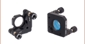
Our Ø19 mm mirror is specifically designed to fit our Polaris® Fixed Optic Mounts for laser system design and other OEM applications. This diameter provides a larger clear aperture than Ø1/2" optics while allowing the mounts to maintain a Ø1" footprint. In addition, our 35 mm x 52 mm mirror is specifically designed for use with the Cerna® Breadboard Top with Two-Position Slider for DIY microscopy.
Except for the Ø0.28" (Ø7 mm) and 35 mm x 52 mm sizes, each mirror has been engraved with the item number on the back of the substrate for easy identification in the lab. The Ø1/2", Ø1", and Ø2" round silver mirrors are also available in packs of 10 at a discount over the individual price.
Care and Handling
Silver coated mirrors require additional care due to their susceptibility to damage from environmental conditions and improper handling. Fingerprints, contact with abrasive surfaces, and environments with high humidity or temperature will diminish the effectiveness of the protective overcoat leaving the silver coating susceptible to oxidation and degradation. When working with silver mirrors, follow standard practices for handling optics. Latex gloves or similar protective coverings are recommended to prevent oil and other residues on the user’s fingers from reaching the optical surface. Even with such precautions, care should be taken not to touch the mirrored face or edges. Silver mirrors should be used and stored in areas at room temperature with minimal humidity. For information on how to clean mirrors and other optics, visit our Optic Cleaning Tutorial.
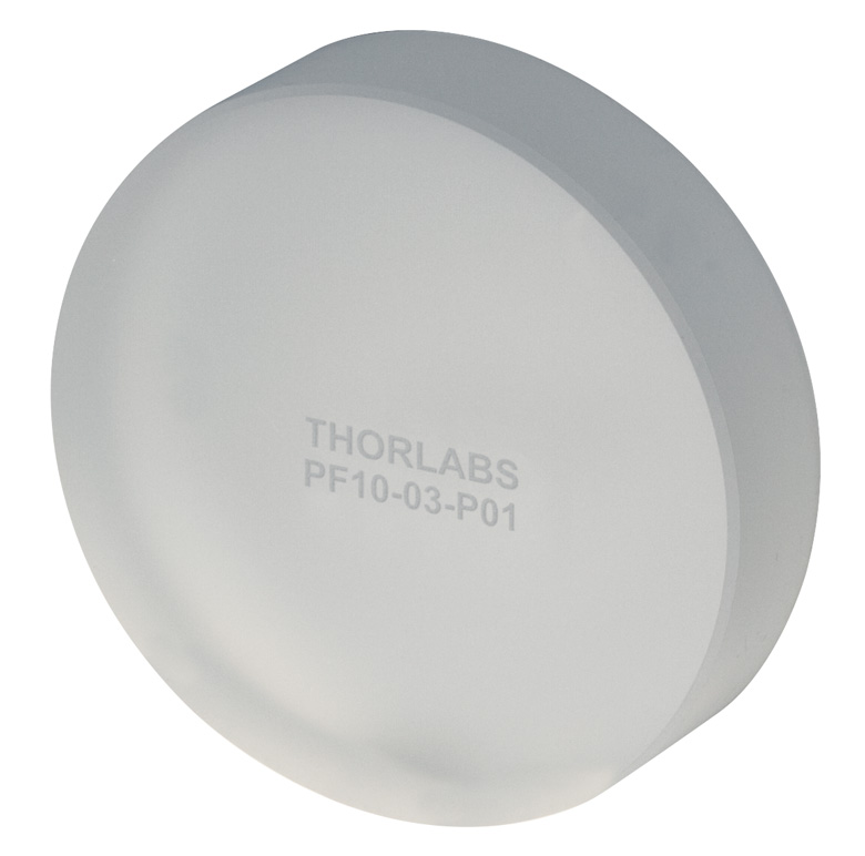
Click to Enlarge
Mirrors Ø1/2" and larger are
laser engraved with their part
number for easy identification.
Custom Metallic Mirrors
Thorlabs' metallic mirrors are manufactured at the production facility housed in our headquarters in Newton, NJ. Our optics business unit has a wide breadth of manufacturing capabilities that allow us to offer a variety of custom optics for both OEM sales and low quantity one-off orders. Custom optic sizes, geometries, substrate materials, and coatings are available with prices on modified stock that are comparable to our stock offerings. We can produce individual custom plano, spherical, and aspheric mirrors as well as custom components for optical systems like our galvanometers. To receive more information or inquire about a custom order, please contact Tech Support.
| Metal-Coated Plano Mirrors Selection Guide | ||||
|---|---|---|---|---|
Wavelength Range |
Avg. Reflectance
|
Coating |
Suffix |
Coating Comparison |
| 250 nm - 450 nm | >90% | UV Enhanced Aluminum | -F01 | Raw Data |
| 450 nm - 20 μm | >90% for 450 nm - 2 µm >95% for 2 - 20 µm |
Protected Aluminum | -G01 | |
| 750 nm - 1 µm | Rs > 99.0% RP > 98.5% |
Ultrafast-Enhanced Silver | -AG | Raw Data |
| 450 nm - 20 μm | >97% for 450 nm - 2 µm >95% for 2 - 20 µm |
Protected Silver | -P01 | |
| Protected Silver | -P02a | |||
| 800 nm - 20 μm | >96% | Protected Gold | -M01 | Raw Data |
| 2 µm - 20 µm | >98% | MIR Enhanced Gold | -M02 | |
| 800 nm - 20 μm | >97% | Unprotected Gold | -M03 | |
| 10.6 µm Laser Line | >99% | Unprotected Gold | -L01 | |
| Metal-Coated Zerodur® Mirrors | ||||
| Economy Front Surface Mirrors with Protected Metallic Coatings | ||||
The shaded regions in the graphs denote the ranges over which we guarantee the specified reflectance. Please note that the reflectance outside of these bands is typical and can vary from lot to lot, especially in out-of-band regions where the reflectance is fluctuating or sloped.

| Damage Threshold Specifications | |
|---|---|
| Coating Designation (Item # Suffix) | Damage Threshold |
| -P01 (Pulsed) | 0.225 J/cm2 (800 nm, 99 fs, 1 kHz, Ø0.167 mm) 1 J/cm2 (1064 nm, 10 ns, 10 Hz, Ø1.010 mm) |
| -P01 (CWa) | 500 W/cm (1.07 µm, Ø0.974 mm) 1500 W/cm (10.6 µm, Ø0.339 mm) |
Damage Threshold Data for Thorlabs' -P01 Coated Protected Silver Mirrors
The specifications to the right are measured data for Thorlabs' protected silver mirrors with a -P01 coating. Damage threshold specifications are constant for this coating type, regardless of the size or shape of the mirror.
Laser Induced Damage Threshold Tutorial
The following is a general overview of how laser induced damage thresholds are measured and how the values may be utilized in determining the appropriateness of an optic for a given application. When choosing optics, it is important to understand the Laser Induced Damage Threshold (LIDT) of the optics being used. The LIDT for an optic greatly depends on the type of laser you are using. Continuous wave (CW) lasers typically cause damage from thermal effects (absorption either in the coating or in the substrate). Pulsed lasers, on the other hand, often strip electrons from the lattice structure of an optic before causing thermal damage. Note that the guideline presented here assumes room temperature operation and optics in new condition (i.e., within scratch-dig spec, surface free of contamination, etc.). Because dust or other particles on the surface of an optic can cause damage at lower thresholds, we recommend keeping surfaces clean and free of debris. For more information on cleaning optics, please see our Optics Cleaning tutorial.
Testing Method
Thorlabs' LIDT testing is done in compliance with ISO/DIS 11254 and ISO 21254 specifications.
First, a low-power/energy beam is directed to the optic under test. The optic is exposed in 10 locations to this laser beam for 30 seconds (CW) or for a number of pulses (pulse repetition frequency specified). After exposure, the optic is examined by a microscope (~100X magnification) for any visible damage. The number of locations that are damaged at a particular power/energy level is recorded. Next, the power/energy is either increased or decreased and the optic is exposed at 10 new locations. This process is repeated until damage is observed. The damage threshold is then assigned to be the highest power/energy that the optic can withstand without causing damage. A histogram such as that below represents the testing of one BB1-E02 mirror.

The photograph above is a protected aluminum-coated mirror after LIDT testing. In this particular test, it handled 0.43 J/cm2 (1064 nm, 10 ns pulse, 10 Hz, Ø1.000 mm) before damage.

| Example Test Data | |||
|---|---|---|---|
| Fluence | # of Tested Locations | Locations with Damage | Locations Without Damage |
| 1.50 J/cm2 | 10 | 0 | 10 |
| 1.75 J/cm2 | 10 | 0 | 10 |
| 2.00 J/cm2 | 10 | 0 | 10 |
| 2.25 J/cm2 | 10 | 1 | 9 |
| 3.00 J/cm2 | 10 | 1 | 9 |
| 5.00 J/cm2 | 10 | 9 | 1 |
According to the test, the damage threshold of the mirror was 2.00 J/cm2 (532 nm, 10 ns pulse, 10 Hz, Ø0.803 mm). Please keep in mind that these tests are performed on clean optics, as dirt and contamination can significantly lower the damage threshold of a component. While the test results are only representative of one coating run, Thorlabs specifies damage threshold values that account for coating variances.
Continuous Wave and Long-Pulse Lasers
When an optic is damaged by a continuous wave (CW) laser, it is usually due to the melting of the surface as a result of absorbing the laser's energy or damage to the optical coating (antireflection) [1]. Pulsed lasers with pulse lengths longer than 1 µs can be treated as CW lasers for LIDT discussions.
When pulse lengths are between 1 ns and 1 µs, laser-induced damage can occur either because of absorption or a dielectric breakdown (therefore, a user must check both CW and pulsed LIDT). Absorption is either due to an intrinsic property of the optic or due to surface irregularities; thus LIDT values are only valid for optics meeting or exceeding the surface quality specifications given by a manufacturer. While many optics can handle high power CW lasers, cemented (e.g., achromatic doublets) or highly absorptive (e.g., ND filters) optics tend to have lower CW damage thresholds. These lower thresholds are due to absorption or scattering in the cement or metal coating.

LIDT in linear power density vs. pulse length and spot size. For long pulses to CW, linear power density becomes a constant with spot size. This graph was obtained from [1].

Pulsed lasers with high pulse repetition frequencies (PRF) may behave similarly to CW beams. Unfortunately, this is highly dependent on factors such as absorption and thermal diffusivity, so there is no reliable method for determining when a high PRF laser will damage an optic due to thermal effects. For beams with a high PRF both the average and peak powers must be compared to the equivalent CW power. Additionally, for highly transparent materials, there is little to no drop in the LIDT with increasing PRF.
In order to use the specified CW damage threshold of an optic, it is necessary to know the following:
- Wavelength of your laser
- Beam diameter of your beam (1/e2)
- Approximate intensity profile of your beam (e.g., Gaussian)
- Linear power density of your beam (total power divided by 1/e2 beam diameter)
Thorlabs expresses LIDT for CW lasers as a linear power density measured in W/cm. In this regime, the LIDT given as a linear power density can be applied to any beam diameter; one does not need to compute an adjusted LIDT to adjust for changes in spot size, as demonstrated by the graph to the right. Average linear power density can be calculated using the equation below.

The calculation above assumes a uniform beam intensity profile. You must now consider hotspots in the beam or other non-uniform intensity profiles and roughly calculate a maximum power density. For reference, a Gaussian beam typically has a maximum power density that is twice that of the uniform beam (see lower right).
Now compare the maximum power density to that which is specified as the LIDT for the optic. If the optic was tested at a wavelength other than your operating wavelength, the damage threshold must be scaled appropriately. A good rule of thumb is that the damage threshold has a linear relationship with wavelength such that as you move to shorter wavelengths, the damage threshold decreases (i.e., a LIDT of 10 W/cm at 1310 nm scales to 5 W/cm at 655 nm):

While this rule of thumb provides a general trend, it is not a quantitative analysis of LIDT vs wavelength. In CW applications, for instance, damage scales more strongly with absorption in the coating and substrate, which does not necessarily scale well with wavelength. While the above procedure provides a good rule of thumb for LIDT values, please contact Tech Support if your wavelength is different from the specified LIDT wavelength. If your power density is less than the adjusted LIDT of the optic, then the optic should work for your application.
Please note that we have a buffer built in between the specified damage thresholds online and the tests which we have done, which accommodates variation between batches. Upon request, we can provide individual test information and a testing certificate. The damage analysis will be carried out on a similar optic (customer's optic will not be damaged). Testing may result in additional costs or lead times. Contact Tech Support for more information.
Pulsed Lasers
As previously stated, pulsed lasers typically induce a different type of damage to the optic than CW lasers. Pulsed lasers often do not heat the optic enough to damage it; instead, pulsed lasers produce strong electric fields capable of inducing dielectric breakdown in the material. Unfortunately, it can be very difficult to compare the LIDT specification of an optic to your laser. There are multiple regimes in which a pulsed laser can damage an optic and this is based on the laser's pulse length. The highlighted columns in the table below outline the relevant pulse lengths for our specified LIDT values.
Pulses shorter than 10-9 s cannot be compared to our specified LIDT values with much reliability. In this ultra-short-pulse regime various mechanics, such as multiphoton-avalanche ionization, take over as the predominate damage mechanism [2]. In contrast, pulses between 10-7 s and 10-4 s may cause damage to an optic either because of dielectric breakdown or thermal effects. This means that both CW and pulsed damage thresholds must be compared to the laser beam to determine whether the optic is suitable for your application.
| Pulse Duration | t < 10-9 s | 10-9 < t < 10-7 s | 10-7 < t < 10-4 s | t > 10-4 s |
|---|---|---|---|---|
| Damage Mechanism | Avalanche Ionization | Dielectric Breakdown | Dielectric Breakdown or Thermal | Thermal |
| Relevant Damage Specification | No Comparison (See Above) | Pulsed | Pulsed and CW | CW |
When comparing an LIDT specified for a pulsed laser to your laser, it is essential to know the following:

LIDT in energy density vs. pulse length and spot size. For short pulses, energy density becomes a constant with spot size. This graph was obtained from [1].
- Wavelength of your laser
- Energy density of your beam (total energy divided by 1/e2 area)
- Pulse length of your laser
- Pulse repetition frequency (prf) of your laser
- Beam diameter of your laser (1/e2 )
- Approximate intensity profile of your beam (e.g., Gaussian)
The energy density of your beam should be calculated in terms of J/cm2. The graph to the right shows why expressing the LIDT as an energy density provides the best metric for short pulse sources. In this regime, the LIDT given as an energy density can be applied to any beam diameter; one does not need to compute an adjusted LIDT to adjust for changes in spot size. This calculation assumes a uniform beam intensity profile. You must now adjust this energy density to account for hotspots or other nonuniform intensity profiles and roughly calculate a maximum energy density. For reference a Gaussian beam typically has a maximum energy density that is twice that of the 1/e2 beam.
Now compare the maximum energy density to that which is specified as the LIDT for the optic. If the optic was tested at a wavelength other than your operating wavelength, the damage threshold must be scaled appropriately [3]. A good rule of thumb is that the damage threshold has an inverse square root relationship with wavelength such that as you move to shorter wavelengths, the damage threshold decreases (i.e., a LIDT of 1 J/cm2 at 1064 nm scales to 0.7 J/cm2 at 532 nm):

You now have a wavelength-adjusted energy density, which you will use in the following step.
Beam diameter is also important to know when comparing damage thresholds. While the LIDT, when expressed in units of J/cm², scales independently of spot size; large beam sizes are more likely to illuminate a larger number of defects which can lead to greater variances in the LIDT [4]. For data presented here, a <1 mm beam size was used to measure the LIDT. For beams sizes greater than 5 mm, the LIDT (J/cm2) will not scale independently of beam diameter due to the larger size beam exposing more defects.
The pulse length must now be compensated for. The longer the pulse duration, the more energy the optic can handle. For pulse widths between 1 - 100 ns, an approximation is as follows:

Use this formula to calculate the Adjusted LIDT for an optic based on your pulse length. If your maximum energy density is less than this adjusted LIDT maximum energy density, then the optic should be suitable for your application. Keep in mind that this calculation is only used for pulses between 10-9 s and 10-7 s. For pulses between 10-7 s and 10-4 s, the CW LIDT must also be checked before deeming the optic appropriate for your application.
Please note that we have a buffer built in between the specified damage thresholds online and the tests which we have done, which accommodates variation between batches. Upon request, we can provide individual test information and a testing certificate. Contact Tech Support for more information.
[1] R. M. Wood, Optics and Laser Tech. 29, 517 (1998).
[2] Roger M. Wood, Laser-Induced Damage of Optical Materials (Institute of Physics Publishing, Philadelphia, PA, 2003).
[3] C. W. Carr et al., Phys. Rev. Lett. 91, 127402 (2003).
[4] N. Bloembergen, Appl. Opt. 12, 661 (1973).

In order to illustrate the process of determining whether a given laser system will damage an optic, a number of example calculations of laser induced damage threshold are given below. For assistance with performing similar calculations, we provide a spreadsheet calculator that can be downloaded by clicking the button to the right. To use the calculator, enter the specified LIDT value of the optic under consideration and the relevant parameters of your laser system in the green boxes. The spreadsheet will then calculate a linear power density for CW and pulsed systems, as well as an energy density value for pulsed systems. These values are used to calculate adjusted, scaled LIDT values for the optics based on accepted scaling laws. This calculator assumes a Gaussian beam profile, so a correction factor must be introduced for other beam shapes (uniform, etc.). The LIDT scaling laws are determined from empirical relationships; their accuracy is not guaranteed. Remember that absorption by optics or coatings can significantly reduce LIDT in some spectral regions. These LIDT values are not valid for ultrashort pulses less than one nanosecond in duration.
A Gaussian beam profile has about twice the maximum intensity of a uniform beam profile.
CW Laser Example
Suppose that a CW laser system at 1319 nm produces a 0.5 W Gaussian beam that has a 1/e2 diameter of 10 mm. A naive calculation of the average linear power density of this beam would yield a value of 0.5 W/cm, given by the total power divided by the beam diameter:
However, the maximum power density of a Gaussian beam is about twice the maximum power density of a uniform beam, as shown in the graph to the right. Therefore, a more accurate determination of the maximum linear power density of the system is 1 W/cm.
An AC127-030-C achromatic doublet lens has a specified CW LIDT of 350 W/cm, as tested at 1550 nm. CW damage threshold values typically scale directly with the wavelength of the laser source, so this yields an adjusted LIDT value:
The adjusted LIDT value of 350 W/cm x (1319 nm / 1550 nm) = 298 W/cm is significantly higher than the calculated maximum linear power density of the laser system, so it would be safe to use this doublet lens for this application.
Pulsed Nanosecond Laser Example: Scaling for Different Pulse Durations
Suppose that a pulsed Nd:YAG laser system is frequency tripled to produce a 10 Hz output, consisting of 2 ns output pulses at 355 nm, each with 1 J of energy, in a Gaussian beam with a 1.9 cm beam diameter (1/e2). The average energy density of each pulse is found by dividing the pulse energy by the beam area:

As described above, the maximum energy density of a Gaussian beam is about twice the average energy density. So, the maximum energy density of this beam is ~0.7 J/cm2.
The energy density of the beam can be compared to the LIDT values of 1 J/cm2 and 3.5 J/cm2 for a BB1-E01 broadband dielectric mirror and an NB1-K08 Nd:YAG laser line mirror, respectively. Both of these LIDT values, while measured at 355 nm, were determined with a 10 ns pulsed laser at 10 Hz. Therefore, an adjustment must be applied for the shorter pulse duration of the system under consideration. As described on the previous tab, LIDT values in the nanosecond pulse regime scale with the square root of the laser pulse duration:
This adjustment factor results in LIDT values of 0.45 J/cm2 for the BB1-E01 broadband mirror and 1.6 J/cm2 for the Nd:YAG laser line mirror, which are to be compared with the 0.7 J/cm2 maximum energy density of the beam. While the broadband mirror would likely be damaged by the laser, the more specialized laser line mirror is appropriate for use with this system.
Pulsed Nanosecond Laser Example: Scaling for Different Wavelengths
Suppose that a pulsed laser system emits 10 ns pulses at 2.5 Hz, each with 100 mJ of energy at 1064 nm in a 16 mm diameter beam (1/e2) that must be attenuated with a neutral density filter. For a Gaussian output, these specifications result in a maximum energy density of 0.1 J/cm2. The damage threshold of an NDUV10A Ø25 mm, OD 1.0, reflective neutral density filter is 0.05 J/cm2 for 10 ns pulses at 355 nm, while the damage threshold of the similar NE10A absorptive filter is 10 J/cm2 for 10 ns pulses at 532 nm. As described on the previous tab, the LIDT value of an optic scales with the square root of the wavelength in the nanosecond pulse regime:
This scaling gives adjusted LIDT values of 0.08 J/cm2 for the reflective filter and 14 J/cm2 for the absorptive filter. In this case, the absorptive filter is the best choice in order to avoid optical damage.
Pulsed Microsecond Laser Example
Consider a laser system that produces 1 µs pulses, each containing 150 µJ of energy at a repetition rate of 50 kHz, resulting in a relatively high duty cycle of 5%. This system falls somewhere between the regimes of CW and pulsed laser induced damage, and could potentially damage an optic by mechanisms associated with either regime. As a result, both CW and pulsed LIDT values must be compared to the properties of the laser system to ensure safe operation.
If this relatively long-pulse laser emits a Gaussian 12.7 mm diameter beam (1/e2) at 980 nm, then the resulting output has a linear power density of 5.9 W/cm and an energy density of 1.2 x 10⁻⁴ J/cm2 per pulse. This can be compared to the LIDT values for a WPQ10E-980 polymer zero-order quarter-wave plate, which are 5 W/cm for CW radiation at 810 nm and 5 J/cm2 for a 10 ns pulse at 810 nm. As before, the CW LIDT of the optic scales linearly with the laser wavelength, resulting in an adjusted CW value of 6 W/cm at 980 nm. On the other hand, the pulsed LIDT scales with the square root of the laser wavelength and the square root of the pulse duration, resulting in an adjusted value of 55 J/cm2 for a 1 µs pulse at 980 nm. The pulsed LIDT of the optic is significantly greater than the energy density of the laser pulse, so individual pulses will not damage the wave plate. However, the large average linear power density of the laser system may cause thermal damage to the optic, much like a high-power CW beam.
| Posted Comments: | |
user
(posted 2024-03-18 18:01:31.973) Hello, can you provide us with phase shift of p- and s-polarized light? We want information about silver ('-P01') and aluminium ('-F01') mirrors. jdelia
(posted 2024-03-19 08:29:26.0) Thank you for contacting Thorlabs. I have contacted you directly to provide you with the requested data. Alberto Martin-Ortega
(posted 2024-03-14 10:28:11.03) We are looking for a product similar to PF40-03-P01, but with a diameter of 200 to 300 mm. Is it possible? ksosnowski
(posted 2024-03-14 12:08:54.0) Hello Alberto, thanks for reaching out to Thorlabs. I have contacted you directly to discuss this potential custom sized mirror. user
(posted 2023-06-19 14:42:50.97) Dear Team
I would really like to know the significance of this 0.225 J/cm2 (800 nm, 99 fs, 1 kHz, Ø0.167 mm) for the damage threshold. Can we take this number as a reference for calculating the damage threshold for a femtosecond laser? cdolbashian
(posted 2023-06-23 11:14:43.0) Thank you for reaching out to us with this inquiry. Unless these pulse parameters exactly match your laser, this number should only be taken as a guideline, as the scaling of ultrashort pulse lasers is not as convenient as for slower pulse lasers or CW lasers. I have contacted you directly to discuss this. user
(posted 2023-04-19 20:58:48.71) What effect do dielectric and metallic mirrors have on linear polarization? Does the linear polarization get changed on getting reflected from them? cdolbashian
(posted 2023-04-26 09:13:59.0) Thank you for reaching out to us with this inquiry. You should expect little to no changes in polarization at normal incidence. However we would expect to see some small changes in polarization at varied incident angles, with the metallic coatings showing a much smaller effect when compared to the dielectric ones. Ivan Zorin
(posted 2023-03-24 09:37:40.093) Dear Madam or Sir,
We have ordered a few mirrors of this type.
In the experiment we have experienced interference artefacts in a fully mirror-based system; therefore, we do suspect it to be due to the coatings.
Could you please tell us about the thickness of the coating on these protective mirrors? And if possible the type of coatings (or it is dispersion profile)?
This would help a lot.
Also, could you please suggest the best alternative for the range of 300-450 nm of uncoated mirrors?
Best regards,
Ivan jgreschler
(posted 2023-04-04 04:13:34.0) Thank you for reaching out to Thorlabs. The thickness of the coating layers is proprietary information, though I can assist you with the available dispersion information we have on hand. I've reached out to the provided email to discuss this further. Guillaume Bourdarot
(posted 2022-12-05 10:33:36.657) Dear Thorlabs support,
In the specs sheet, the surface flatness is provided for your mirror.
For a metrology experiment, I would like to know the surface *roughness* that is achieved (in nm rms).
Would it be possible to share this information?
Best regards,
Guillaume cdolbashian
(posted 2022-12-15 02:34:44.0) Thank you for reaching out to us Guillaume! While we do not have an official spec for this, I have reached out to you directly to discuss expected typical/nominal values. Martin Kunz
(posted 2022-10-17 16:43:32.317) Hi there:
What are the chances I can convince you to make some of the protected silver mirrors (e.g. PFSQ10-03-P01 and PFSQ20-03-P01) with glassy carbon substrates instead of fused silica. They'd be transparent to X-rays but relflective to visible and IR light. jdelia
(posted 2022-10-27 10:06:16.0) Thank you for contacting Thorlabs. I have reached out to you directly to discuss the feasibility of this custom request. Diane R
(posted 2022-09-26 19:08:51.767) Hi there,
Would it please be possible to get the reflectance data for these silver coated mirrors at normal incidence?
Kind regards,
Diane cdolbashian
(posted 2022-10-04 03:43:12.0) Good afternoon Diane, I have reached out to you with our data which is closest to normal incidence. Martin Buckthorpe
(posted 2022-09-08 10:05:48.797) Hi there. Could you provide reflectivity data for the protected silver coatings at 0 deg AOI? Many thanks Marina Servol
(posted 2022-01-27 17:25:21.433) Hello,
I would like to know the thickness of the silver layer on the P01 mirror. Could you give me this information ?
Thanks for your help.
Sincerely,
Marina jdelia
(posted 2022-01-31 02:28:27.0) Thank you for contacting Thorlabs. Unfortunately, this information is proprietary. However, we can say that it is on the order of hundreds of nm. Dylan Black
(posted 2021-10-26 22:07:42.343) Hi, can you provide the phase shift information for s and p polarized light on the PF10-03-P01? Thank you! YLohia
(posted 2021-12-23 11:07:01.0) Hello, phase shift data for these mirrors can be requested by emailing techsupport@thorlabs.com. I have reached out to you directly with a theoretical estimate. user
(posted 2021-10-13 22:56:52.51) Dear Sir, Madam,
what is the GDD of the PF10-03-P01 mirrors at 800 nm? In your description you state that this mirrors should be suited for femto second applications, but I cannot find any additional data.
Best, Mark YLohia
(posted 2021-12-22 02:55:58.0) Hello Mark, GDD data can be requested by emailing techsupport@thorlabs.com. I have reached out to you directly about this. Akbar Safari
(posted 2021-09-09 12:43:36.35) Hello, Would you please provide the phase shift data between s- and p-polarization for angle of incidence = 30 and 45 degrees, at 780nm for your protected silver mirror? Thank you! YLohia
(posted 2021-09-09 03:37:51.0) Hello, phase shift data (theoretical) can be requested by emailing techsupport@thorlabs.com. I have reached out to you directly with this information. Chang Kyun Ha
(posted 2021-04-05 11:14:08.74) Hello, is there any available data about the phase shift of s-pol. and p-polarized light (AOT = 45°) incident on protected silver mirrors? Thank you! YLohia
(posted 2021-04-05 02:11:02.0) Hello, we will reach out to you directly with phase shift information. user
(posted 2021-02-27 00:06:45.14) Hi, what is the approximate weight of the PF05-03-P01 mirror? YLohia
(posted 2021-03-12 04:03:24.0) The approx. weight is given in the machine drawing (https://www.thorlabs.com/_sd.cfm?fileName=7710-E0W.pdf&partNumber=PF05-03-P01) as 2g. jessica QI
(posted 2021-02-19 09:31:27.36) what is the tolerance of the diameter?外径公差是多少 YLohia
(posted 2021-02-19 10:42:49.0) Hello, the outer diameter tolerance of the PF10-03-P01 is listed in the specs table below as +0.0 mm / -0.1 mm. Andrea Fioretti
(posted 2020-10-01 08:11:09.01) Dear SIrs,
is it possible to have data about the phase shift of the s and p polarizations for 45° incidence on protected silver mirrors? Thanks in advance, Andrea Fioretti YLohia
(posted 2020-10-01 10:31:42.0) Hello Andrea, thank you for contacting Thorlabs. We will reach out to you directly with this data. user
(posted 2020-09-11 01:16:54.813) Add-on: It would also be great to get the phase-shift data asked for a few times below, at 632 nm. Thanks! Maria user
(posted 2020-09-11 01:12:04.56) Dear Sir or Madam,
I am encountering strong variations in reflectance (polarization- and angle-resolved, i.e., R(AOI,p-pol,s-pol)) between different mirrors of the same kind (protected silver PF10-03-P01). Could this be due to variations in the thickness of the SiO2 cover layer? If possible, could you please specify the layer-thickness and especially its variation more precisely than "approximately 100 nm"? Are there other possible reasons for the variation? Thanks in advance.
Best regards
Maria YLohia
(posted 2020-09-24 03:38:00.0) Hello Maria, unfortunately, we cannot offer specific numbers on the layer thickness as that information is proprietary. This variation can certainly be an artifact of that, among other possibilities involving inconsistencies in the setup. I have reached out to you directly to troubleshoot this. user
(posted 2020-09-02 10:37:55.577) Dear Sir/Madam,
I was wondering whether there are also reflectance graphs available at different angles then 45 and 12, for example at 35 and 55 degrees AOI and normal incidence?
I am using the PFSQ10-03-P01 mirror.
It would help me a lot with my research.
Best,
Lisanne YLohia
(posted 2020-09-02 11:28:23.0) Hello Lisanne, thank you for contacting Thorlabs. I have reached out to you directly with some AOI information. Henry King
(posted 2020-07-10 16:15:02.297) 我在反射镜参数中看到了“Parallelism”这个参数。不是很明白这个参数的意义。它是反映反射镜表面整体上凸起或凹下去的程度吗。是改变平行光的平行度的原因吗?请问平面镜对平行光的平行度的改变应该看哪个参数? YLohia
(posted 2020-07-10 10:26:54.0) Thank you for contacting Thorlabs. An applications engineer from our team in China will reach out to you directly. Alexander Schultze
(posted 2020-05-08 10:29:31.96) I am using a tenpack of silver protected mirror and I see a strong impact on my phase at AOI 45. Could you kindly provide me the phase shift data of this mirror (and unprotected, protected gold) for comparison. YLohia
(posted 2020-05-08 10:47:57.0) Thank you for contacting Thorlabs. I will reach out to you with this data. Jale Schneider
(posted 2020-01-27 16:25:27.42) Dear Sir or Madam,
to integrate on a shutter blade, I need a custom sized protected silver mirror (ideally P-02) with a size of 17 x 24x 1.1 mm. Is it possible to manufacture such a mirror? Thickness can be 1 mm as well. Wavelength range is 450 - 2 um.
Best regards
Jale YLohia
(posted 2020-01-27 12:40:20.0) Hello Jale, thank you for contacting Thorlabs. Custom items can be requested by emailing techsupport@thorlabs.com. We will reach out to you directly to discuss your requirement. user
(posted 2019-08-27 22:10:21.347) hello,
is this product, or similar, available in a ~1mm thickness?
kindest regards,
daniel
opto-mechanical designer YLohia
(posted 2019-08-28 10:01:11.0) Hello Daniel, thank you for contacting Thorlabs. We offer the PFR10-P01, which has a 1mm thickness. Custom items can be requested by emailing techsupport@thorlabs.com. Emma Deist
(posted 2019-08-07 16:39:59.1) Hello,
Do you have reflectance data at a 67.5 degree angle of incidence?
Thanks,
Emma YLohia
(posted 2019-08-28 10:08:00.0) Hello Emma, thank you for contacting Thorlabs. We have reached out to you directly with this information. Ste Am
(posted 2019-05-29 08:56:38.94) Hello, which mount can I use with the mirror PF30-03-P01 ?
Thank you. YLohia
(posted 2019-06-04 03:10:46.0) Hello, thank you for contacting Thorlabs. The KS3 and the LMR3 are a couple of options for this mirror. We have reached out to you directly, in case you have specific mounting requirements. sebastian.schaefer
(posted 2019-03-12 13:47:03.047) Can you produce something like PF20-03-P01 but with a 45° hole in the center? The hole diameter would be something between 1-5mm or so. nbayconich
(posted 2019-03-13 10:58:48.0) Thank you for contacting Thorlabs. I'll reach out to you directly to discuss our custom capabilities. gaoyang
(posted 2019-02-13 14:08:33.067) Hello,could you give me the datasheet of PF05-03-P01 ? YLohia
(posted 2019-02-14 09:33:19.0) Hello, thank you for contacting Thorlabs. All technical information is given on the specs table found in the Overview tab of this page. The technical drawing and specs can also be found here: https://www.thorlabs.com/_sd.cfm?fileName=7710-E0W.pdf&partNumber=PF05-03-P01 user
(posted 2019-02-07 08:01:32.61) How should CW LIDT data be interpreted for millisecond pulsed lasers?
Let's say we have a 1070nm, 1kW-10ms-10Hz pulsed laser with 10mm diameter.
Should I compare 500W/cm limit versus the 1kW peak power (fail) or versus the 1kW*10ms*10Hz=100W average power (pass) ?
Thank you YLohia
(posted 2019-02-22 10:20:27.0) Hello, thank you for contacting Thorlabs. Since this is a relatively long pulse, the damage threshold spec should be compared to the 1kW peak power. user
(posted 2018-12-01 00:06:01.327) Is mirror surface flatness specified as Peak-to-Valley or RMS value? Thanks YLohia
(posted 2018-12-03 10:39:57.0) Hello, the surface flatness of our mirrors are specified as Peak-to-Valley. jeremy.raskop
(posted 2018-10-11 16:59:59.49) Hello, is it possible to acquire a silver-coated mirror such as this one, but with a thickness of less than a cm ? Thank you. nbayconich
(posted 2018-10-17 04:48:45.0) Thank you for contacting Thorlabs. Yes we can provide this as a custom option. I will reach out to you directly to discuss our custom capabilities. sebastian.schaefer
(posted 2018-09-20 09:19:29.257) Do you have any data on the transmission of light through the silver coated mirrors? I am looking for a large flat mirror (protected silver coated) with a very small fraction of the light going through the mirror. nbayconich
(posted 2018-09-24 10:25:47.0) Thank you for contacting Thorlabs. Please see the link below to our backside polished mirrors page.
https://www.thorlabs.com/newgrouppage9.cfm?objectgroup_id=3831
Here we have transmission data for our protected silver coated backside polished mirrors along with several dielectric coated mirrors. The silver coating allows little transmission over it's recommended operating range. benjamin.powell
(posted 2018-09-11 08:36:17.16) Hi,
I’m struggling to reproduce the reflectance spectrum provided on the website of the protected silver mirror (PF03-03-P01) accurately in the 350-1000nm range .
I’ve tried measuring the reflectance spectrum with an ellipsometer and a reflectometer. But my results seem to have quite big (5-10%) errors.
Would someone at Thorlabs be able to shed some light on how the reflectance spectrum provided on the website was measured?(what referance was used)
Regards,
Benjamin nbayconich
(posted 2018-09-19 01:24:39.0) Thank you for contacting Thorlabs. For the UV to NIR range we measure our mirrors with the perkin Elmer lambda 950 spectrophotometer, this is used from 190nm-2600nm. A baseline scan is performed before scanning each optic meaning the scan within the 190nm -2600nm performs an absolute measurement scan rather than a relative scan which requires a reference optic. A techsupport representative will reach out to you directly to discuss your application. user
(posted 2016-07-26 14:43:22.563) Is there any specification regarding the surface roughness of your mirrors? lzeldin
(posted 2016-05-13 10:36:38.81) FYI your units in you excel sheet for the various coating say (nm) when they should be microns besembeson
(posted 2016-05-17 08:37:18.0) Response from Bweh at Thorlabs USA: Thanks for bringing this to our attention. We have corrected this. kuszewski
(posted 2016-03-23 09:24:40.113) I would like to ask if you have information on how the protected silver mirrors(especially
PF10-03-P01) changed the polarization for the 700nm and for 45 deg and aigu angle of incident light? besembeson
(posted 2016-03-25 09:06:28.0) Response from Bweh at Thorlabs USA: At the moment, we have data at 633nm which I will share with you by email. We plan on having data that includes this wavelength subsequently. maxime.bayle
(posted 2016-02-22 11:23:47.43) Can you give more information about the coating of the mirrors ? Is there only SiO2 ? I really need to know the exact structure composition and can't find it with ellipsometric measurements (SiO2/Ag). besembeson
(posted 2016-03-04 02:23:06.0) Response from Bweh at Thorlabs USA: It is like we specify on the website, silver mirror coating with the SiO2 protective layer. zs4d
(posted 2015-08-04 17:41:35.793) Can you cut the 1 mm thick silver mirror to custom size and shape? Specifically, cut it into two or four pieces for a galvo scanner application. What would be the surface flatness of such pieces of about 10 mm dimensions? What would be the lead time and price? besembeson
(posted 2015-08-18 09:37:30.0) Response from Bweh at Thorlabs USA: We can provide such custom sized optics. I will followup by email regarding quotation. h.vural
(posted 2014-10-16 11:56:04.263) Very interested in how this mirror effects polarization. Can you please make phase shift data available. I am interested in phase shifts in the range 850 - 900 (especially 873) nm at 45 AOI, if you wish to send me the data directly. jlow
(posted 2014-10-16 02:52:48.0) Response from Jeremy at Thorlabs: We do not have comprehensive data on this available at the moment but we can share some preliminary test data. I will contact you directly about this. adr5109
(posted 2014-01-17 18:40:02.097) Can some information be given regarding how this mirror coating holds up to femtosecond pulses? The damage threshold isn't very useful, especially, if it's advertised as having nearly 0 GVD, which would basically be for fs systems. I read in the 400/800 mirrors feedback the response, "the coating is designed to withstand 1.5W of 800nm ultrafast pulses with durations as short as 50fs and 300mW of 400nm ultrafast pulses with durations as short as 50fs, at a minimum diameter of 1.2mm" Do you have similar knowledge for silver? gold?
Thanks a lot,
Adam jlow
(posted 2014-01-27 02:09:32.0) Response from Jeremy at Thorlabs: We do not have a spec on the damage threshold for femtosecond pulses. However, we have had feedback from a customer who used our protected metal mirrors without any problem with a 2.5 mJ laser (800 nm, 1 kHz rep rate, 60fs FWHM). julia.maerk
(posted 2013-06-14 15:13:02.02) Hello Thorlab,
could you give me some advice/send me some information on how best to clean the protected silver mirror surface?
Kind regards,
Julia jlow
(posted 2013-06-18 11:46:00.0) Response from Jeremy at Thorlabs: We have an optics cleaning tutorial at http://www.thorlabs.com/tutorials.cfm?tabID=26066 which details the cleaning procedure for typical optics. I would recommend first blowing off the dust from the surface and then do the drop and drag method afterwards. tcohen
(posted 2012-10-15 12:07:00.0) Response from Tim at Thorlabs: Thank you very much for your feedback! We are further investigating polarization phase shift of our mirrors to be able to publish our results. Before publication can be done we will need to evaluate this in the production process and current inventory. As this may take some time, I will contact you with the theoretical data directly. ke.claytor
(posted 2012-10-12 09:34:08.91) Very interested in how this mirror (and your other coatings) effects polarization. Can you please make phase shift data available online? I am interested in phase shifts in the range 600 - 900 nm at 45 AOI, if you wish to send me the data directly. sharrell
(posted 2012-09-24 10:23:00.0) Response from Sean at Thorlabs: Thank you for your feedback! I will send you the newest data for our silver coating directly. In addition, I will update the silver coating curve plot across our website and add a link to download this data to all of the appropriate pages today. tcohen
(posted 2012-08-16 14:28:00.0) Response from Tim at Thorlabs: Thank you for contacting us. I have sent the requested data for your review. julielutti
(posted 2012-08-16 11:54:14.0) Hello, I would also like to have the phase shift data for those mirrors at 45degrees AOI - 600-900nm spectral region. Thanks tcohen
(posted 2012-07-12 11:42:00.0) Response from Tim at Thorlabs: In order to clean your mirror, please first blow off the optic to remove any contaminants. After this, please lightly moisten a lintless wipe, such as a lens tissue or Webril Wipe, with an optical grade solvent, such as acetone. At this point you can employ the drop and drag method or applicator method as detailed in our Optics Cleaning Tutorial at http://www.thorlabs.com/tutorials.cfm?tabID=26066. This tutorial discusses recommended handling and cleaning methods in depth. If you have any questions on any specific cleaning methods, please contact us at techsupport@thorlabs.com. user
(posted 2012-07-11 09:54:23.0) how to clean fingerprint on the protected silver mirror? thanks tcohen
(posted 2012-07-05 11:30:00.0) Response from Tim at Thorlabs: These have a parallelism of <3 arcmin. For convenience, this and further specifications can be found on the “Specs” tab on this page. salerno.anthony92
(posted 2012-07-04 14:58:08.0) Hello there. I was wondering exactly how parallel are the front and back surfaces of the mirrors?
Cheers. tcohen
(posted 2012-06-28 11:08:00.0) Response from Tim at Thorlabs: Thank you for your interest in our protected silver mirrors! I have contacted you with phase shift data. ph
(posted 2012-06-28 11:43:24.0) Hi, how does the protected silver mirror (45° AOI) affect polarization of a linearly polarized CO2 laser beam (@10.6 µm)? Do you have phase shift data or other data for this? tcohen
(posted 2012-06-01 09:27:00.0) Response from Tim at Thorlabs: Thank you for your feedback! I have contacted you directly with the data. jfu
(posted 2012-05-31 13:33:48.0) I am particularly interested in phase shift data for waverlength of 1064nm
Thanks jfu
(posted 2012-05-31 11:53:23.0) Could you send me the data of phase shift for protected silver coated mirror? for both p and s polarization? bdada
(posted 2012-01-23 08:46:00.0) Response from Buki at Thorlabs:
Thank you for using our feedback forum. There is a SiO2 overcoat with a typical thickness of 100nm. p.j.j.mangeol
(posted 2012-01-06 08:27:21.0) Dear Sir or Madam,
I would need to know how thick is the protective layer. For my application it would be great if it was smaller than 50nm or so. Do you have an number?
What are the physicochemical properties of the surface: does it respond like glass?
Best regards,
PM bdada
(posted 2011-08-22 16:27:00.0) Response from Buki at Thorlabs:
Thank you for your feedback. The coating is SiO2. We will correct the mistake on our website. user
(posted 2011-08-19 14:16:09.0) Is there a reason why SiO coating is used instead of more common SiO2? jjurado
(posted 2011-08-17 09:45:00.0) Response from Javier at Thorlabs to matthias.raunhardt: The damage threshold is mainly dictated by the peak power of the laser used. As a guideline, lasers with pulse duration in the range of 10 ns to 10 us can cause damage by dielectric breakdown and by thermal absorption. matthias.raunhardt
(posted 2011-08-10 08:21:06.0) Hello. According to your specifications, damage breakdown of the silver coating appears at 3 J/cm2 at 1064 nm, 10 ns, 10 Hz, Ø1.000 mm. Is this damage caused by average or by peak power?
In our application just the breakdown because of average power is important. Can you state on that?
Thank you very much. Regards. chienchunglee
(posted 2011-06-09 17:10:35.0) How thick is the SiO overcoat? jjurado
(posted 2011-02-16 17:05:00.0) Response from Javier at Thorlabs to mbrodeur: Thank you for submitting your request. We currently do not offer optic components in ZERODUR substrate. However, we may be able to offer these mirrors as part of a special production. I will contact you directly to get more details. mbrodeur
(posted 2011-02-16 09:49:36.0) looking for VNIR mirror I did not see
30mm dia or square
spectral response 400-1000nm
prefer silver coating,and appropriate protective coatings
zeodur material jjurado
(posted 2011-02-03 11:48:00.0) Response from Javier at Thorlabs to achmyro: Thank you very much for contacting us. The ratio between cross section/diameter that allows us to maintain 1/10 wave surface flatness is 4:1. In this case we can go down to a thickness of 3.2 mm. If we modify an already coated mirror by grinding it down to a smaller thickness, it is very likely that the grinding process will introduce stress to the part, reducing the flatness from 1/10 wave to 1/4 wave. I will contact you directly to discuss your application. achmyro
(posted 2011-02-03 16:24:44.0) Is it possible to get a rectangular mirror like PFSQ05-03-P01 on a thinner substrate while still maintaining high surface flatness? What will be the minimal thickness? tor
(posted 2010-11-11 17:25:07.0) Response from Tor at Thorlabs to Nick: Thank you for your inquiry. I am locating the reflectivity data for both of these coatings along your wavelength of interest; once its available, I will share it with you. In the meantime, the following reflectivity can be expected from the protected aluminum mirrors: Ravg > 90% from 450 nm - 2 µm, Ravg > 95% from 2 - 20 µm; from the protected silver mirrors, Ravg > 97.5% from 450 nm - 2 µm, Ravg > 96% from 2 - 20 µm can be expected. nick
(posted 2010-11-10 12:57:16.0) Can you please confirm the reflectance percentage from ~1 to 10um for both protected silver and protected aluminum of your products? Thorlabs
(posted 2010-08-13 17:05:39.0) Response from Javier at Thorlabs to cdurfee: Thank you for your feedback. I will send you data of the phase shift generated by these silver coated mirrors. cdurfee
(posted 2010-08-12 11:41:51.0) Are there measurements or calculations about what the phase shift is vs wavelength? We have a lot of these mirrors, but Im concerned that the wavelength-dependent phase shift affects our ultrafast laser pulses centered at 800nm. Adam
(posted 2010-05-05 14:41:31.0) A response from Adam at Thorlabs to sebastian: Currently, we do not have CW damage threshold specifications for our metallic mirrors. We will be sending these out for testing and expect to have information back by the end of this month. sebastian.beyer
(posted 2010-05-04 14:01:46.0) You list these mirrors Laser Damage Threshold for pulsed lasers. Can you give specifications for the use with cw lasers as well? Greg
(posted 2010-04-28 15:54:17.0) A response from Greg at Thorlabs to gsh: I have added reflectivity data for our other metallic mirrors. Links for this data can be found next to the reflectivity graphs. Thank you for giving us feedback on our website! Adam
(posted 2010-04-28 12:55:28.0) A response from Adam to gsh: We can certainly add this data to the website. We will make sure we add these graphs. In the meantime, I will email you the data you are looking for. gsh
(posted 2010-04-28 10:39:06.0) You have the raw data for the gold mirror reflectivity at 0 deg and 45 degrees, but you dont have the data for silver or aluminium listed. Are these data available? acable
(posted 2008-02-06 09:19:45.0) It would be nice to have measured reflectivity plots included on the Overview tab for all the metalic mirrors as a quick reference tool. I would suggest that the curve start at the 90% points so as to provide a clear picture of the performance of the mirror.
It would also be nice to have plots from a couple of different lots provided on the Graphs tab to show the variability of the reflectivity. At the bottom of this tab i would also suggest that you show the plots of the other metallic mirrors with links to the various types that you sell. Very often i have a broadband source and need to pick from the various metallic coatings and i find myself hopping around to piece the data together. I would guess many visitors would have the requirements.
If possible i would also find it useful to have links embedded in the Overview tab that would allow me to hop around to the various metallic mirrors. |

 Zoom
Zoom| Item # | PF03-03-P01 | PF05-03-P01 | PF07-03-P01 | PF10-03-P01 | PF15-03-P01 | PF20-03-P01 | PF30-03-P01 | PF40-03-P01 | |
|---|---|---|---|---|---|---|---|---|---|
| Diameter | 7.0 mm (0.28") |
0.5" (12.7 mm) |
19.0 mm (0.75") |
1.0" (25.4 mm) |
1.5" (38.1 mm) |
2.0" (50.8 mm) |
3.0" (76.2 mm) |
4.0" (101.6 mm) |
|
| Diameter Tolerance | +0.0 mm / -0.1 mm | ||||||||
| Thickness | 2.0 mm (0.08") | 6.0 mm (0.24") | 12.0 mm (0.47") | 0.75" (19.1 mm) | |||||
| Thickness Tolerance | ±0.2 mm | ||||||||
| Reflectance (Average) | >97% for 450 nm - 2 µm, >95% for 2 - 20 µm | ||||||||
| Substrate | Fused Silica | ||||||||
| Surface Flatness (Peak to Valley) |
λ/10 @ 633 nm | ||||||||
| Surface Quality | 40-20 Scratch-Dig | ||||||||
| Parallelism | <3 arcmin | ||||||||
| Clear Aperture | >90% of Diameter | ||||||||
| Damage Threshold |
Pulsed | 0.225 J/cm2 (800 nm, 99 fs, 1 kHz, Ø0.167 mm) 1 J/cm2 (1064 nm, 10 ns, 10 Hz, Ø1.010 mm) |
|||||||
| CWa | 500 W/cm (1.07 µm, Ø0.974 mm) 1500 W/cm (10.6 µm, Ø0.339 mm) |
||||||||

 Zoom
Zoom
| Item # | PFSQ05-03-P01 | PFSQ10-03-P01 | PFSQ20-03-P01 | PFR10-P01 | PFR14-P02 | |
|---|---|---|---|---|---|---|
| Face Dimensions | 1/2" x 1/2" (12.7 mm x 12.7 mm) |
1" x 1" (25.4 mm x 25.4 mm) |
2" x 2" (50.8 mm x 50.8 mm) |
25.0 mm x 36.0 mm (0.98" x 1.42") |
35.0 mm x 52.0 mm (1.38" x 2.05") |
|
| Face Dimensions Tolerance | +0.0 mm / -0.1 mm | ±0.1 mm | ||||
| Thickness | 6.0 mm (0.24") | 1.0 mm (0.04") | 2.0 mm (0.08") | |||
| Thickness Tolerance | ±0.2 mm | ±0.1 mm | ||||
| Reflectance (Average) | >97% for 450 nm - 2 µm >95% for 2 - 20 µm |
|||||
| Substrate | UV Fused Silica | |||||
| Surface Flatness (Peak to Valley) |
λ/10 @ 633 nm | λ/8 @ 633 nm | λ @ 633 nm | λ/4 @ 633 nm | ||
| Surface Quality | 40-20 Scratch-Dig | 10-5 Scratch-Dig | ||||
| Parallelism | <3 arcmin | |||||
| Clear Aperture | >90% of Dimension | 90%, Elliptical | ||||
| Damage Threshold |
Pulsed | 0.225 J/cm2 (800 nm, 99 fs, 1 kHz, Ø0.167 mm) 1 J/cm2 (1064 nm, 10 ns, 10 Hz, Ø1.010 mm) |
- | |||
| CWa | 500 W/cm (1.07 µm, Ø0.974 mm) 1500 W/cm (10.6 µm, Ø0.339 mm) |
- | ||||