 Products Home / Technical Resources / Polarization Optics Technical Publications / Quartz-Wedge Depolarizer Tutorial
Quartz-Wedge Depolarizer Tutorial

Please Wait

Spatial Periodicity in the Polarization of the Output Beam
The spatial periodicity in the polarization of the output beam of the polarizer is easily observed when a linearly polarized monochromatic light source is used. The linearly polarized monochromatic beam must have a beam waist larger than 6 mm to generate this spatial periodicity. To observe this effect, place the quartz-wedge depolarizer in the beam so that propagation direction of the beam is normal to and incident upon the thicker wedge of the depolarizer.
To detect the beam's spatial periodicity, place a linear polarizer (analyzer) after the beam exits the quartz-wedge depolarizer. The intensity variation will be banded as shown in the false-color plots shown below. The banding occurs because the degree to which the state of polarization is rotated is identical along any line perpendicular to the thick wedge incline. Several examples of different incident and depolarizer angles are discussed below.
Example 1:
In the first example, a 635 nm, linearly polarized source with a 20 mm beam waist is used. The source light is incident on and propogating normal to the thick wedge of the depolarizer. The light is polarized in the same direction as the optic (fast) axis of the thick wedge. The optic axis of the thin wedge is at a 45o angle with respect to both the incident light polarization and the optic axis of the thick wedge. In this orientation, the wedge incline is also oriented parallel to the incident light polarization.
The orientation of the input polarization and optic axis of the thick and thin wedges is shown in Figure 1. The input polarization is shown in red, the thick wedge optic axis in blue, and the thin wedge optic axis in green. The flat on the top of the depolarizer drawing (solid blue line) is cut perpendicular to the thick wedge optic axis. The flat on the side of the drawing (dashed blue line) is cut perpendicular to the thin wedge optic axis.
A theoretical plot showing the spatially-dependent polarization angle is shown in Figure 2. This false-color plot shows the polarization angle of the output beam from the quartz-wedge depolarizer based on the input beam characteristics described above.
The bands in the false-color plot represent different regions of identical polarization with polarizations varying from being completely along the horizontal axis (perpendicular to the input polarization) to completely along the vertical axis (parallel to the input beam polarization). The separation between the two polarizations in this case is approximately 2 mm. The orientation of the bands are always perpendicular with the thick wedge optic axis, and in this case, are also perpendicular to the input polarization.
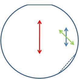
Figure 1. Input polarization in a parallel arrangement with the optic axis of the thick wedge.
Click to Enlarge
Figure 2. False-color plot of a calculation showing a linearly polarized input beam parallel to the optic axis of the thick wedge after passing through the depolarizer.
Example 2:
In this example, the same linearly polarized source is used, except the polariation is oriented parallel to the optic axis of the thin wedge and at a 45 degree angle from the optic axis of the thick wedge. The orientation of the input polarization and optic axes of the thick and thin wedges are shown in Figure 3. The input polarization is shown in red, the thick wedge optic axis in blue, and the thin wedge optic axis in green. The flat on the top of the depolarizer drawing (solid blue line) is cut perpendicular to the thick wedge optic axis. The flat on the side of the drawing (dashed blue line) is cut perpendicular to the thin wedge optic axis.
The calculated result for the source and orientation passing through the quartz-wedge depolarizer is shown in Figure 4. As described in Figure 2, the bands in the false-color plot represent the the spatially-dependent regions of identical polarization. Note the orientation of the banding is perpendicular to the optic axis of the thick wedge (and wedge incline as well). The orientation of the input beam has no effect on the orientation of the banding.
Rotating the input polarization only affects the specific polarization of the band. This is easily observed by comparing the bands at 0 mm on the vertical axis in Figs. 2 and 4. In Figure 2, the band at 0 mm has a 45o orientation while in Figure 4, the band at 0 mm has a 90o orientation.
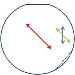
Figure 3. Input polarization in a parallel arrangement with the
optic axis of the thin wedge.
Click to Enlarge
Figure 4. False-color plot of a calculation showing a linearly polarized input beam parallel to the optical axis of the thin wedge after passing through the depolarizer.
Example 3:
In this last example, the input beam has the same characteristics as in Example 1. However, the quartz-wedge depolarizer is rotated 45o so the input polarization is parallel to the optic axis of the thin wedge. This arrangement is shown in Fig. 5. The input polarization (red arrow) is still incident on the thick wedge; however, it is now perpendicular to the thin wedge flat.
The false-color plot in Fig. 6 shows the calculation result of the input beam described above passing through the quartz-wedge depolarizer. The orientation of the banding is clearly different from the banding in Figs. 2 and 4. The 45o tilt in the pattern is because the banding occurs perpendicular to both the optic axis of the thick wedge and wedge incline.
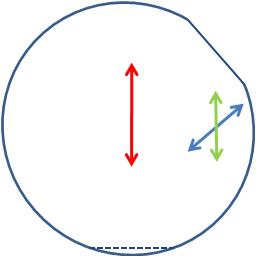
Figure 5. Input polarization in a parallel arrangement with the
optic axis of the thin wedge and 45o to the wedge plane.
Click to Enlarge
Figure 6. False-color plot of a calculation showing a linearly polarized input beam parallel to the optic axis of the thin wedge after passing through the depolarizer at a 45o angle to the wedge plane.
| Depolarizer Comparison Table | ||
|---|---|---|
| Depolarizer Type | LCP Patterned Retarder | Quartz-Wedge Design |
| Effective Beam Size | Down to Ø0.5 mm | Down to Ø6 mm |
| Surface Quality | 60-40 Scratch-Dig | 10-5 Scratch Dig |
| Thickness | 3.2 mm (0.13") | 7.35 mm (0.289") |
| Available Wavelengths | 350 - 700 nm (AR Coated) 650 - 1050 nm (AR Coated) 1050 - 1700 nm (AR Coated) |
190 - 2500 nm (Uncoated) 350 - 700 nm (AR Coated) 650 - 1050 nm (AR Coated) 1050 - 1700 nm (AR Coated) |
The following plots compare the degree of polarization (DOP) that can be achieved using the liquid crystal polymer (LCP) patterned depolarizers and our quartz-wedge depolarizers. Compared to the quartz wedge depolarizers, the LCP patterned depolarizers show greater performance stability with changing angle of incidence and can effectively depolarize smaller beam sizes, which is especially useful for laser applications. In contrast, the quartz-wedge depolarizers have a higher surface quality and damage threshold. They also provide better performance for depolarizing elliptically and circularly polarized light.
Degree of Polarization vs. Beam Size
Click to Enlarge
The DPP25-A is an LCP depolarizer and the DPU-25-A is one of Thorlabs' quartz-wedge depolarizers. This test was performed using a 532 nm CPS532 laser diode module (1 nm FWHM bandwidth).
Click to Enlarge
The DPP25-B is an LCP depolarizer and the DPU-25-B is one of Thorlabs' quartz-wedge depolarizers. This test was performed using a 780 nm CPS192 laser diode module (1 nm FWHM bandwidth).
Click to Enlarge
The DPP25-C is an LCP depolarizer and the DPU-25-C is one of Thorlabs' quartz-wedge depolarizers. This test was performed using a 1310 nm MCLS1-1310 laser diode module (1 nm FWHM bandwidth).
Degree of Polarization vs. Wavelength
Click to Enlarge
The DPP25-A is an LCP depolarizer and the DPU-25-A is one of Thorlabs' quartz-wedge depolarizers. This test was performed at three wavelengths using three different lasers with a Ø4 mm beam size: 405 nm (CPS405, 1 nm FWHM bandwidth), 532 nm (CPS532, 1 nm FWHM bandwidth), and 633 nm (previous-generation HRS015, <10 pm FWHM bandwidth).
Click to Enlarge
The DPP25-B is an LCP depolarizer and the DPU-25-B is one of Thorlabs' quartz-wedge depolarizers. This test was performed at three wavelengths using three different lasers with a Ø4 mm beam size: 670 nm (CPS186, 1 nm FWHM bandwidth), 780 nm (CPS192, 1 nm FWHM bandwidth), and 980 nm (CPS980, 1 nm FWHM bandwidth).
Click to Enlarge
The DPP25-C is an LCP depolarizer and the DPU-25-C is one of Thorlabs' quartz-wedge depolarizers. This test was performed at three wavelengths using three different lasers with a Ø4 mm beam size: 1064 nm (1.5 nm FWHM bandwidth), 1310 nm (MCLS1-1310, 1 nm FWHM bandwidth), and 1550 nm (previous-generation TLS001-1550 T-Cube™, 1 nm FWHM bandwidth).
Depolarizer Transmission
Click to Enlarge
The DPP25-A is an LCP depolarizer and the DPU-25-A is one of Thorlabs' quartz-wedge depolarizers.

Click to Enlarge
The DPP25-B is an LCP depolarizer and the DPU-25-B is one of Thorlabs' quartz-wedge depolarizers.
Click to Enlarge
The DPP25-C is an LCP depolarizer and the DPU-25-C is one of Thorlabs' quartz-wedge depolarizers.
Degree of Polarization vs. Angle of Incidence
Click to Enlarge
The DPP25-A is an LCP depolarizer and the DPU-25-A is one of Thorlabs' quartz-wedge depolarizers. This test was performed using a 532 nm CPS532 laser diode module (1 nm FWHM bandwidth) with a beam size of Ø1 mm.
Click to Enlarge
The DPP25-B is an LCP depolarizer and the DPU-25-B is one of Thorlabs' quartz-wedge depolarizers. This test was performed using a 780 nm laser diode module (CPS192, 1 nm FWHM bandwidth) with a beam size of Ø1 mm.
Click to Enlarge
The DPP25-C is an LCP depolarizer and the DPU-25-C is one of Thorlabs' quartz-wedge depolarizers. This test was performed using a 1310 nm MCLS1-1310 laser diode module (1 nm FWHM bandwidth) with a beam size of Ø1 mm.
Degree of Polarization vs. Rotation Angle
The plot below is provided as an example of the variation in Degree of Polarization as the depolarizer is rotated. Actual performance will vary from depolarizer to depolarizer, depending on the alignment of the LCP pattern and the section of the depolarizer illuminated by the incident beam. Rotating a depolarizer around an axis perpendicular to its surface does cause some variation in performance, but overall, the LCP depolarizer still provides a lower degree of polarization for a Ø0.5 mm beam than the quartz-wedge design. Similar results can be expected from the -B and -C depolarizers.
Click to Enlarge
The plot above shows the performance of the depolarizer as it is rotated. The test was performed using a 532 nm CPS532 laser diode module (1 nm FWHM bandwidth) with a beam size of Ø0.5 mm. For the quartz-wedge depolarizer, 0° corresponds to the cut edge marking the fast axis of the thick wedge. For the LCP depolarizer, 0° corresponds to the line of parallel fast-axes orientations (see the Overview tab for a plot of the fast-axis orientations).
| Posted Comments: | |
| No Comments Posted |