 Products Home
Imperial and Metric Threading
Metric
Imperial

Please Wait

| Some Differences Between Imperial and Metric Parts | ||
|---|---|---|
| 1" = 25.4 mm (Exactly) | ||
| Quantity of Merit | Imperial | Metric |
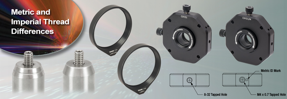
| "Small" Tap | 8-32 | M4 x 0.7 (Usually Called "M4") |
| "Large" Tap | 1/4"-20 | M6 x 1.0 (Usually Called "M6") |
| Spacing Between Taps on Breadboards | 1" | 25.0 mm |
| Thorlabs Item Number | - | /M or -EC Suffix |
Choosing Between Thorlabs' Imperial, Metric, and Universal Parts
Contents
- Tapped Parts have Imperial and Metric Versions
- Universal Parts Use Cap Screws to Attach to Other Parts
- Imperial and Metric Parts Use Different Basic Units of Length
- Imperial and Metric Parts Accept the Same Optic Sizes
- SM-Threaded Holes Do Not Differ Between Imperial and Metric Parts
- Mechanical Drawings Give Design Units First
As part of Thorlabs' commitment to serve the international photonics community, we design our products for compatibility with imperial and metric setups. When it is possible for one part to fulfill the needs of both imperial and metric customers simultaneously, only one part (which we call "universal") is developed and sold. However, when it is not feasible or useful for a single part to satisfy both standards, Thorlabs designs both an imperial item and a metric equivalent.
TR2 Imperial Post Contains 8-32 and 1/4"-20 Taps
TR50/M Metric Post Contains M4 and M6 Taps
Tapped Parts have Imperial and Metric Versions
Generally speaking, the distinction between imperial and metric parts is most important when the part has mechanical mounting features that make use of threaded, tapped holes. A tapped hole is a hole that allows you to screw in a setscrew or cap screw and is only compatible with one threading type. Since both imperial and metric thread standards exist, parts that use threaded mounting holes must have both imperial and metric versions.
For example, consider Thorlabs' TR Posts, which contain two tapped holes. For imperial customers, we manufacture TR posts with an 8-32-threaded hole on one end and a 1/4"-20-threaded hole on the other. However, for metric customers, our TR/M posts contain an M4-threaded hole on one end and an M6-threaded hole on the other. An imperial TR post cannot be directly used with a metric breadboard, and a metric TR post cannot be directly used with an imperial breadboard. Therefore, two versions must exist.
In contrast, consider Thorlabs' KM100 Kinematic Mirror Mount. These parts use counterbored holes (which have smooth edges) for mounting, rather than threads. The lack of threading means that either 8-32 or M4 cap screws can be dropped right in. Therefore, only one version, which we call a "universal" version, has been designed. For more information on universal mounts, please see the "How Do I Use a Universal Mount?" section below.
To limit confusion for our customers who have both imperial and metric optomechanics, metric parts typically include an identification marker not present on the imperial equivalent. For example, as shown to the right, our metric TR posts are machined with a ring on the tapered edge next to the M4-threaded hole. Other examples of metric ID marks are shown in the drawings that appear later in this tutorial.
A setup may combine universal and imperial parts, or it may combine universal and metric parts, but without specialized hardware (such as our threading adapters), imperial and metric parts cannot be combined.
| Parts designed for metric setups have "/M" or "-EC" at the end of their item number. |
| Metric items are usually physically marked to differentiate them from imperial parts. |
Universal Parts Use Cap Screws to Attach to Other Parts
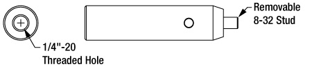
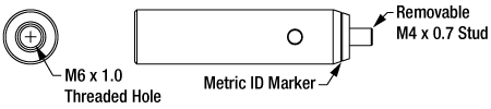
Universal mounts do not contain threaded holes for mounting. Hence, a common question that we receive is how to attach a universal mount to an imperial or metric post since our posts ship with either an 8-32 or M4 setscrew installed. This setscrew is easily removed with a 5/64" or 2 mm balldriver or hex key, which exposes an 8-32 or M4 threading. An 8-32 or M4 cap screw can then be inserted through the universal mount and tightened into the vacated tapped hole.
Since universal parts are designed to be used with cap screws, we typically include both imperial and metric cap screws with each item. To know if a part is universal, simply check the part's webpage to see if we manufacture imperial and metric versions separately.
|
How Do I Use a Universal Mount?  Click to Enlarge The 8-32 (M4) stud in our posts contains a hex head that accepts a 5/64" (2 mm) balldriver or hex key. 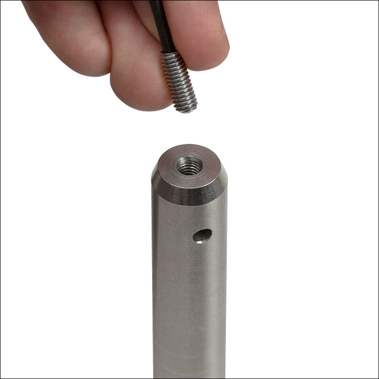 Click to Enlarge Using a balldriver or hex key, remove the stud. This exposes an 8-32 (M4) threading. 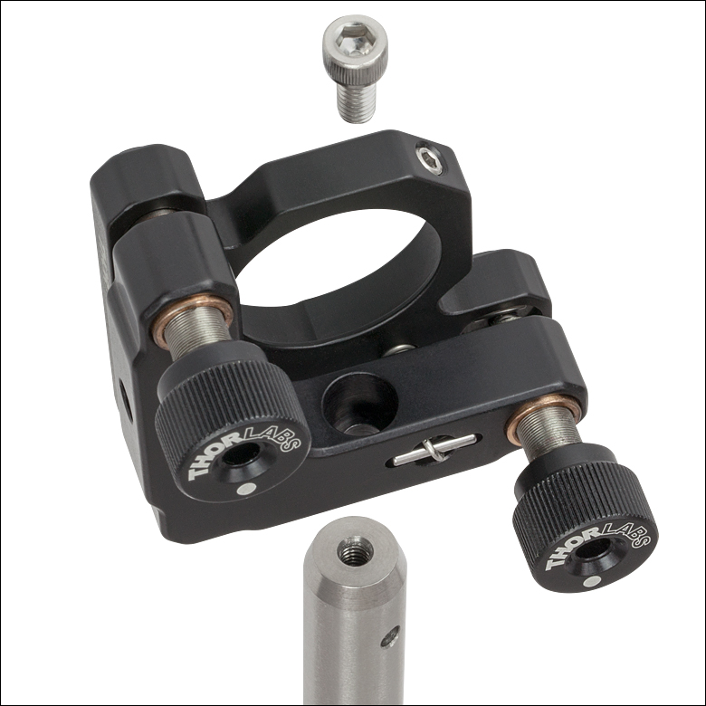 Click to Enlarge Insert an 8-32 (M4) cap screw through the counterbored hole in the universal mount, and tighten it into the post on the other side of the hole. 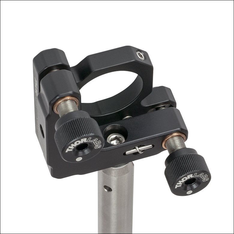 Click to Enlarge The post-mounted universal mount is ready to accept an optic. |
Imperial and Metric Parts Use Different Basic Units of Length
The imperial and metric distinction is also important in product lines that are distinguished by their mechanical dimensions. Again, consider our TR posts. The imperial versions of these come in several discrete lengths: 1" (25.4 mm), 1.5" (38.1 mm), 2" (50.8 mm), and greater. However, the metric versions of these come in different discrete lengths: 30 mm (1.18"), 40 mm (1.57"), 50 mm (1.97"), and greater. In other words, we customize our imperial and metric versions so that they come in measurements that make sense for the intended customers.
Click to Enlarge
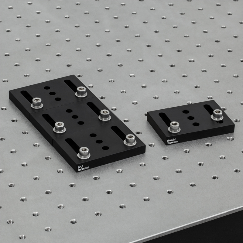
If a BA2/M base is placed parallel and perpendicular to the tapped hole matrix of an imperial optical table, one of the screws will not be able to tighten and mechanical stability will be sacrificed.
Click to Enlarge
Here, BA2 and BA2/M bases have been bolted to an imperial optical table. Several BA2's can be located adjacent to each other without any issues. However, the BA2/M is forced to rotate in order to be secured, wasting table space.
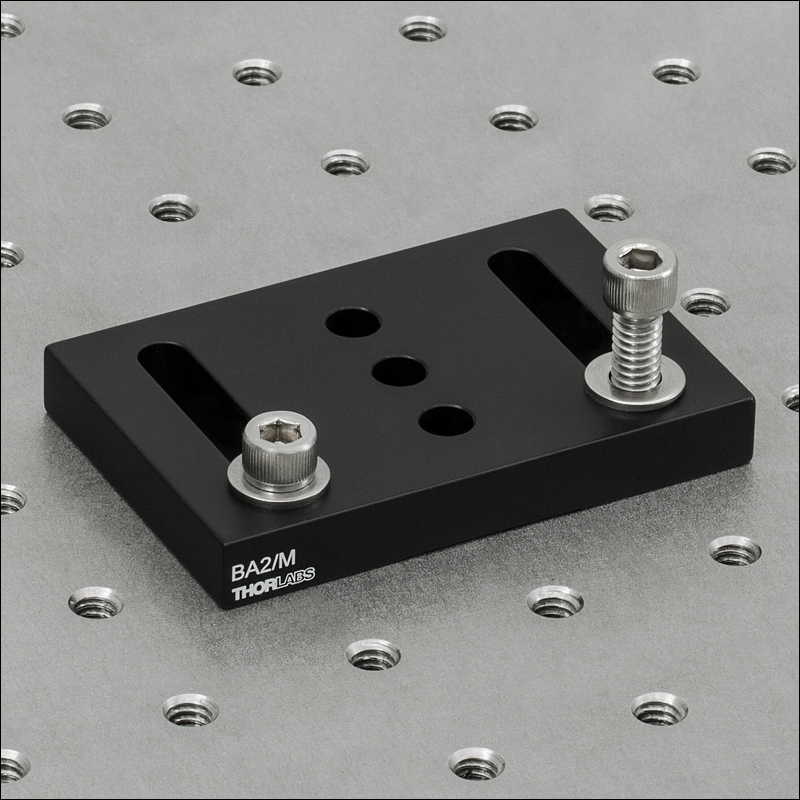
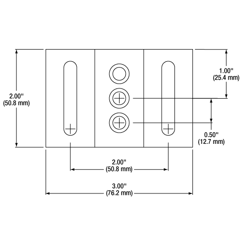
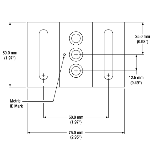
As a consequence of these differences, it is generally best to use imperial parts with imperial setups and metric parts with metric setups, even when the parts contain universal features. For example, Thorlabs' BA2 and BA2/M Post Holder Bases include counterbored mounting holes and counterbored mounting slots, which can be considered universal since counterbores are not threaded. However, the holes and slots of a BA2 base (imperial) are positioned to exactly align with the tapped hole matrix of an imperial breadboard, while the holes and slots of a BA2/M base (metric) exactly align with the tapped hole matrix of a metric breadboard.
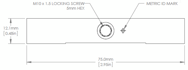
In addition, the outer dimensions of the BA2 are 2" x 3" x 3/8" (50.8 mm x 76.2 mm x 9.5 mm), while the outer dimensions of the BA2/M are 50 mm x 75 mm x 10 mm (1.97" x 2.95" x 0.39"). These slight differences mean that several BA2 (or BA2/M) bases may be placed in physical contact on imperial (or metric) optical tables without leaving unused rows of holes.
Part Naming Conventions
In situations where the key differences between parts in the same family are their mechanical dimensions, the naming may change between imperial and metric versions. This is done for convenience and readability. For example, our 1" TR post is named TR1, our 1.5" TR post is named TR1.5, and our 2" TR post is named TR2. The number after the TR prefix indicates the length of the part (in imperial units). Now consider the naming of metric posts: our 30 mm TR post is named TR30/M, our 40 mm TR post is named TR40/M, and our 50 mm TR post is named TR50/M. In these parts, the extra digit in the name allows us to name them by their natural length units—that is, TR30/M has one more digit in its name than TR1. This does not mean than the TR30/M is thirty times as long!
In general, we try to keep part numbers as short as practical, so there may not always be an extra digit in the item number of metric parts. In these cases, you may rely on the /M suffix to tell you if the part is metric. For example, consider our Aluminum Breadboards. The MB1012 is an imperial 10" x 12" breadboard (with 1/4"-20 tapped holes at 1" spacings), while the MB1560/M is a metric 15 cm x 60 cm breadboard (with M6 tapped holes at 25 mm spacings). Both of these parts have four digits in their part numbers, but one is imperial and the other is metric.
Click to Enlarge
BA2 Dimensions are Optimized for Imperial Setups
Click to Enlarge
BA2/M Dimensions are Optimized for Metric Setups
Imperial and Metric Parts Accept the Same Optic Sizes
| At Thorlabs, imperial and metric equivalents of a part accept the same optic diameters. |
Click to Enlarge
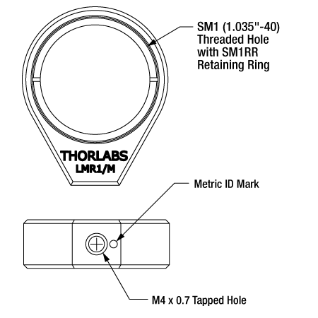
LMR1/M Metric Lens Mount is SM1-Threaded, Accepts Optics up to Ø25.4 mm, and Contains an M4 Tap
Click to Enlarge
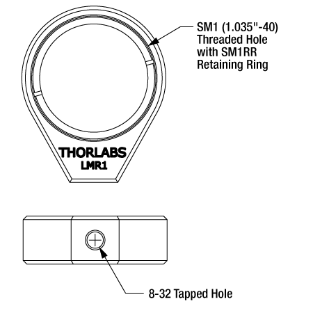
LMR1 Imperial Lens Mount is SM1-Threaded, Accepts Optics up to Ø1", and Contains an 8-32 Tap
It is often assumed that the metric version of a mount is designed for optics with metric design units. For example, there are two versions of the LMR1 Mount for Ø1" Optics: the LMR1, which has an 8-32-threaded mounting hole, and the LMR1/M, which has an M4-threaded mounting hole. You might expect that the LMR1 is designed for Ø1" (Ø25.4 mm) optics and that the LMR1/M is designed for Ø25.0 mm optics. In fact, the LMR1 and LMR1/M both accept Ø25.4 mm optics (and both use the same SM1RR Retaining Ring).
This has two immediate consequences. First, the LMR1/M is not too small for Ø1" optics, so the mount can accommodate optics up to 1" in diameter without a problem. However, the LMR1/M will not perfectly center Ø25.0 mm optics. This may be a concern for applications in which centration is critical, as in any application that uses a lens.
Some drawings on our website may not make it clear that imperial and metric parts have the same bore size. This impression usually results from rounding (read the section titled "Mechanical Drawings Give Design Units First" below). Should any questions arise as you plan your setup, please contact Technical Support for assistance.
| SM Threading Standardsa | ||
|---|---|---|
| Name | Optic Size | Threading |
| SM05 | Ø1/2" (Ø12.7 mm) | 0.535"-40 |
| SM1 | Ø1" (Ø25.4 mm) | 1.035"-40 |
| SM30 | Ø30 mm | M30.5 x 0.5 |
| SM2 | Ø2" (Ø50.8 mm) | 2.035"-40 |
| SM3 | Ø3" (Ø76.2 mm) | 3.035"-40 |
SM-Threaded Holes Do Not Differ Between Imperial and Metric Parts
| SM threadings are identical between imperial parts and their metric equivalents. |
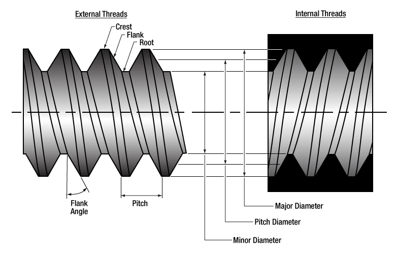
Thorlabs has developed a family of in-house threading standards for common optic diameters, denoted with the SM prefix. These threads provide a convenient way to center, secure, and position optics in their mounts. Because we have extensively deployed the SM standards across our entire optomechanical product line, you can be assured that the parts you buy from us are made to be mechanically compatible. A list of the common SM prefixes and their associated optic diameters is shown in the table to the right.
In optic mounts, the /M suffix only refers to the tapped mounting holes. In other words, when Thorlabs designates an SM-threaded product as imperial or metric, the SM-threaded hole is the same in both versions.
Mechanical Drawings Give Design Units First
Thorlabs provides mechanical drawings for nearly all its parts in PDF and DXF file formats, and the vast majority of parts also have 3D models in SolidWorks, eDrawing, and Step file formats. The PDF and DXF drawings include each part's design measurements, call out important physical features of each product (such as mounting holes, metric ID marks, and specialized features like locking screws and retaining rings), and are the basis for the sketches shown in this tutorial and elsewhere on our website. They can be accessed by clicking on the Docs Icon on the webpage of the part.
The measurements in each drawing are given in either imperial units, with a metric conversion in brackets; or metric units, with an imperial conversion in brackets. The units that are listed first are the design units. By convention, we give imperial measurements to two decimal places (hundredths of an inch) and metric measurements to one decimal place (tenths of a millimeter), since standard machine tolerances are ±0.005" (roughly ±0.1 mm).
| Converted measurements in Thorlabs' drawings may be rounded. |
Although the measurements in the design units of the part are always exact to this precision, the converted measurements may be rounded. For example, if a converted measurement on a drawing is not given to the stated precision (two decimal places for imperial dimensions and one decimal place for metric dimensions), it has been rounded, although the presence of the conventional number of digits after the decimal does not guarantee that rounding has not occurred. We abandoned the practice of rounding some years ago, but it still surfaces in drawings that have not yet been updated. Therefore, if you need to use a measurement conversion, it is prudent to check the conversion yourself, using the design units as the basis. 1" is exactly 25.4 mm.
Should you have any concerns about reading a mechanical drawing, please contact Tech Support for assistance.

Click to Enlarge
Our BA2F Flexure Clamping Base has imperial design units. Therefore, its drawing gives the product dimensions in inches, with a metric conversion shown in brackets.
Click to Enlarge
Our BA2F/M Flexure Clamping Base has metric design units. Therefore, its drawing gives the product dimensions in millimeters, with an imperial conversion shown in brackets.
| SM05 Threading: Ø1/2" Lens Tubes, 16 mm Cage Systems | |||
|---|---|---|---|
| External Thread, 0.535"-40.0 UNS-2A | Internal Thread, 0.535"-40.0 UNS-2B | ||
| Max Major Diameter | 0.5340" | Min Major Diameter | 0.5350" |
| Min Major Diameter | 0.5289" | Min Pitch Diameter | 0.5188" |
| Max Pitch Diameter | 0.5178" | Max Pitch Diameter | 0.5230" |
| Min Pitch Diameter | 0.5146" | Min Minor Diameter (and 83.3% of thread) | 0.508" |
| Max Minor Diameter | 0.5069" | Max Minor Diameter (and 64.9% of thread) | 0.514" |
| RMS Threading: Objective, Scan, and Tube Lenses | |||
|---|---|---|---|
| External Thread, 0.800"-36.0 UNS-2A | Internal Thread, 0.800"-36.0 UNS-2B | ||
| Max Major Diameter | 0.7989" | Min Major Diameter | 0.8000" |
| Min Major Diameter | 0.7934" | Min Pitch Diameter | 0.7820" |
| Max Pitch Diameter | 0.7809" | Max Pitch Diameter | 0.7866" |
| Min Pitch Diameter | 0.7774" | Min Minor Diameter (and 83.3% of thread) | 0.770" |
| Max Minor Diameter | 0.7688" | Max Minor Diameter (and 64.9% of thread) | 0.777" |
| C-Mount Threading: Machine Vision Lenses, CCD/CMOS Cameras | |||
|---|---|---|---|
| External Thread, 1.000"-32.0 UN-2A | Internal Thread, 1.000"-32.0 UN-2B | ||
| Max Major Diameter | 0.9989" | Min Major Diameter | 1.0000" |
| Min Major Diameter | 0.9929" | Min Pitch Diameter | 0.9797" |
| Max Pitch Diameter | 0.9786" | Max Pitch Diameter | 0.9846" |
| Min Pitch Diameter | 0.9748" | Min Minor Diameter (and 83.3% of thread) | 0.966" |
| Max Minor Diameter | 0.9651" | Max Minor Diameter (and 64.9% of thread) | 0.974" |
| SM1 Threading: Ø1" Lens Tubes, 30 mm Cage Systems | |||
|---|---|---|---|
| External Thread, 1.035"-40.0 UNS-2A | Internal Thread, 1.035"-40.0 UNS-2B | ||
| Max Major Diameter | 1.0339" | Min Major Diameter | 1.0350" |
| Min Major Diameter | 1.0288" | Min Pitch Diameter | 1.0188" |
| Max Pitch Diameter | 1.0177" | Max Pitch Diameter | 1.0234" |
| Min Pitch Diameter | 1.0142" | Min Minor Diameter (and 83.3% of thread) | 1.008" |
| Max Minor Diameter | 1.0068" | Max Minor Diameter (and 64.9% of thread) | 1.014" |
| SM30 Threading: Ø30 mm Lens Tubes | |||
|---|---|---|---|
| External Thread, M30.5 x 0.5 – 6H/6g | Internal Thread, M30.5 x 0.5 – 6H/6g | ||
| Max Major Diameter | 30.480 mm | Min Major Diameter | 30.500 mm |
| Min Major Diameter | 30.371 mm | Min Pitch Diameter | 30.175 mm |
| Max Pitch Diameter | 30.155 mm | Max Pitch Diameter | 30.302 mm |
| Min Pitch Diameter | 30.059 mm | Min Minor Diameter (and 83.3% of thread) | 29.959 mm |
| Max Minor Diameter | 29.938 mm | Max Minor Diameter (and 64.9% of thread) | 30.094 mm |
| SM1.5 Threading: Ø1.5" Lens Tubes | |||
|---|---|---|---|
| External Thread, 1.535"-40 UNS-2A | Internal Thread, 1.535"-40 UNS-2B | ||
| Max Major Diameter | 1.5339" | Min Major Diameter | 1.535" |
| Min Major Diameter | 1.5288" | Min Pitch Diameter | 1.5188" |
| Max Pitch Diameter | 1.5177" | Max Pitch Diameter | 1.5236" |
| Min Pitch Diameter | 1.5140" | Min Minor Diameter (and 83.3% of thread) | 1.508" |
| Max Minor Diameter | 1.5068" | Max Minor Diameter (and 64.9% of thread) | 1.514" |
| SM2 Threading: Ø2" Lens Tubes, 60 mm Cage Systems | |||
|---|---|---|---|
| External Thread, 2.035"-40.0 UNS-2A | Internal Thread, 2.035"-40.0 UNS-2B | ||
| Max Major Diameter | 2.0338" | Min Major Diameter | 2.0350" |
| Min Major Diameter | 2.0287" | Min Pitch Diameter | 2.0188" |
| Max Pitch Diameter | 2.0176" | Max Pitch Diameter | 2.0239" |
| Min Pitch Diameter | 2.0137" | Min Minor Diameter (and 83.3% of thread) | 2.008" |
| Max Minor Diameter | 2.0067" | Max Minor Diameter (and 64.9% of thread) | 2.014" |
| SM3 Threading: Ø3" Lens Tubes | |||
|---|---|---|---|
| External Thread, 3.035"-40.0 UNS-2A | Internal Thread, 3.035"-40.0 UNS-2B | ||
| Max Major Diameter | 3.0337" | Min Major Diameter | 3.0350" |
| Min Major Diameter | 3.0286" | Min Pitch Diameter | 3.0188" |
| Max Pitch Diameter | 3.0175" | Max Pitch Diameter | 3.0242" |
| Min Pitch Diameter | 3.0133" | Min Minor Diameter (and 83.3% of thread) | 3.008" |
| Max Minor Diameter | 3.0066" | Max Minor Diameter (and 64.9% of thread) | 3.014" |
| Posted Comments: | |
Dat Vu
(posted 2021-04-23 04:46:21.93) Hello Thorlabs,
My name is Dat Vu from Viettel High Technology Industries Corporation.
I would like to ask about the specification of the aluminum material you used in many opto-mechanic products in your catalog. Most of them is black, so I wonder whether they are black-anodized aluminum or not.
I'm looking forward to your respond.
Thank you! YLohia
(posted 2021-04-23 11:34:54.0) Hello Dat, thank you for contacting Thorlabs. We use 6061-T6 aluminum for most of our optomechanical products. These are indeed black-anodized (if the surface of the material looks black as opposed to grey). |