 Products Home / Optical Elements / Diffraction Gratings / Visible Ruled Reflective Diffraction Gratings
Visible Ruled Reflective Diffraction Gratings
- Gratings with 400 nm or 500 nm Blaze Wavelengths
- High Grating Efficiency of 60 to 80% at the Blaze Wavelength
GR50A-0605
50 mm x 50 mm
500 nm Blaze
Wavelength
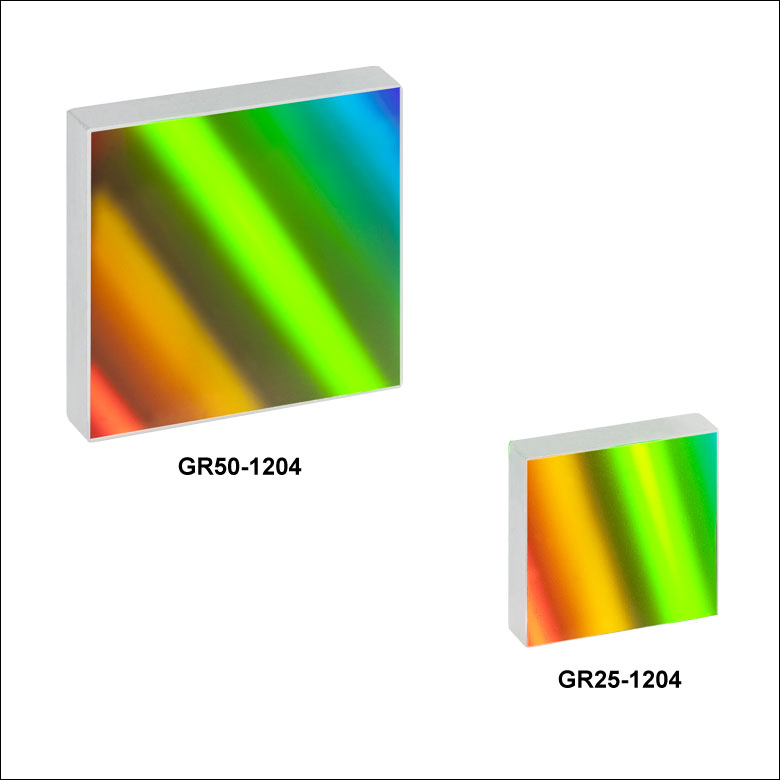
GR25-1204
25 mm x 25 mm
400 nm Blaze Wavelength
GR13-1205
12.7 mm x 12.7 mm
500 nm Blaze
Wavelength
See the Gratings Tutorial Tab Below for Definitions and Equations


Please Wait
| Selection Guide | |
|---|---|
| Transmission Gratings | |
| Ruled | UV |
| Visible | |
| Near IR | |
| Volume Phase Holographic |
Visible |
| Near IR | |
| Reflective Gratings | |
| Ruled | UV |
| Visible | |
| Near IR | |
| Mid IR | |
| Holographic | |
| Echelle | |
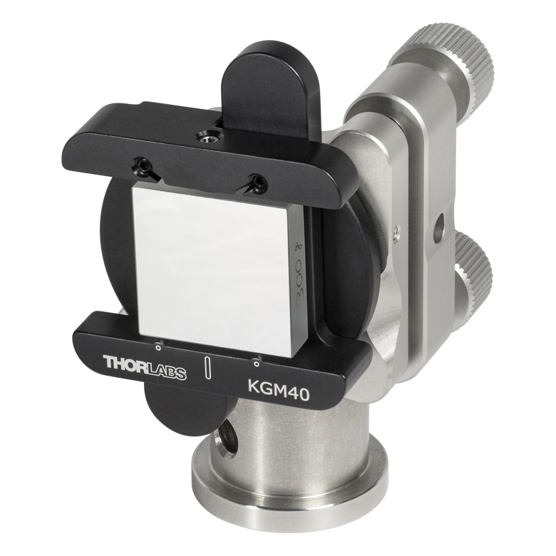
Click to Enlarge
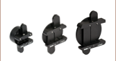
Diffraction Grating Mounted in
Polaris Mirror Mount Using Diffraction Grating Adapter
Features
- Blaze Wavelengths of 400 or 500 nm
- High Grating Efficiency of 60% to 80% at the Blaze Wavelength
- Low Ghosting, <0.5% of Parent Line
- Aluminum Reflective Coating
- Soda Lime Glass Substrate with 300 to 1200 Grooves/mm
- Produced from Ruled Original
Thorlabs offers ruled diffraction gratings for use in the visible region. These gratings will have a relatively sharp efficiency peak about their blaze wavelength and are produced from ruled originals. They are offered with different blaze angles to suit a variety of applications in spectroscopy and analysis where high efficiency is of primary concern. For more information, please click on the Gratings Tutorial tab above. We also offer reflective holographic gratings, which do not produce ghosting effects at the expense of efficiency. For information regarding the differences between grating types, please click on the Gratings Guide tab above.

Click to Enlarge
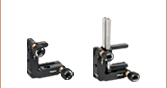
Ruled Diffraction Grating Used in
Littrow Configuration (θi=γ)
(Note: 1st Order Beam is Collinear and Antiparallel to Incident Beam)
Please note that these gratings are bare aluminum and do not contain an overcoat. However, custom MgF2 or gold coatings are available to protect the aluminum surface of the gratings. The gold coating offers high performance in the IR, while the MgF2 coating offers the best protection; contact Tech Support for further details.
Mounts and Adapters
Thorlabs offers a variety of mounts and adapters for precise and stable mounting and aligning square optics. All of Thorlabs' gratings can be mounted directly into the KM100C Right-Handed or KM100CL Left-Handed Kinematic Rectangular Optic Mount. Gratings can also be mounted in one of three Kinematic Grating Mount Adapters which can be used with any of Thorlabs' Ø1" Mirror Mounts, including the POLARIS-K1E Ultra-Stable Kinematic Mirror Mount.
Warning
Optical gratings can be easily damaged by moisture, fingerprints, aerosols, or the slightest contact with any abrasive material. Gratings should only be handled when necessary and always held by the sides. Latex gloves or a similar protective covering should be worn to prevent oil from fingers from reaching the grating surface. No attempt should be made to clean a grating other than blowing off dust with clean, dry air or nitrogen. Solvents will likely damage the grating's surface.
Thorlabs uses a clean room facility for assembly of gratings into mechanical setups. If your application requires integrating the grating into a sub-assembly or a setup please contact Tech Support to learn more about our assembly capabilities.
Diffraction Gratings Tutorial
- Introduction
- Blazed (Ruled) Gratings
- Volume Phase Holographic Transmission Gratings
- Holographic Reflective Gratings
Introduction
Diffraction gratings, either transmissive or reflective, can separate different wavelengths of light using a repetitive structure embedded within the grating. The structure affects the amplitude and/or phase of the incident wave, causing interference in the output wave. In the transmissive case, the repetitive structure can be thought of as many tightly spaced, thin slits. Solving for the irradiance as a function wavelength and position of this multi-slit situation, we get a general expression that can be applied to all diffractive gratings when ![]() = 0°,
= 0°,

(1)
known as the grating equation. The equation states that a diffraction grating with spacing ![]() will deflect light at discrete angles (
will deflect light at discrete angles (![]() ), dependent upon the value
), dependent upon the value ![]() λ, where
λ, where ![]() is the order of principal maxima. The diffracted angle,
is the order of principal maxima. The diffracted angle, ![]() , is the output angle as measured from the surface normal of the diffraction grating. It is easily observed from Eq. 1 that for a given order
, is the output angle as measured from the surface normal of the diffraction grating. It is easily observed from Eq. 1 that for a given order ![]() , different wavelengths of light will exit the grating at different angles. For white light sources, this corresponds to a continuous, angle-dependent spectrum.
, different wavelengths of light will exit the grating at different angles. For white light sources, this corresponds to a continuous, angle-dependent spectrum.
Figure 1. Transmission Grating
Transmission Gratings
One popular style of grating is the transmission grating. The sample diffraction grating with surfaces grooves shown in Figure 1 is created by scratching or etching a transparent substrate with a repetitive series of narrow-width grooves separated by distance ![]() . This creates areas where light can scatter.
. This creates areas where light can scatter.
The incident light impinges on the grating at an angle ![]() , as measured from the surface normal. The light of order
, as measured from the surface normal. The light of order ![]() exiting the grating leaves at an angle of
exiting the grating leaves at an angle of ![]() , relative to the surface normal. Utilizing some geometric conversions and the general grating expression (Eq. 1) an expression for the transmissive diffraction grating can be found:
, relative to the surface normal. Utilizing some geometric conversions and the general grating expression (Eq. 1) an expression for the transmissive diffraction grating can be found:

(2)
where both ![]() and
and ![]() are positive if the incident and diffracted beams are on opposite sides of the grating surface normal, as illustrated in the example in Figure 1. If they are on the same side of the grating normal,
are positive if the incident and diffracted beams are on opposite sides of the grating surface normal, as illustrated in the example in Figure 1. If they are on the same side of the grating normal, ![]() must then be considered negative.
must then be considered negative.
Figure 2. Reflective Grating
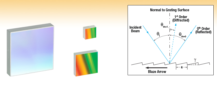
Reflective Gratings
Another very common diffractive optic is the reflective grating. A reflective grating is traditionally made by depositing a metallic coating on an optic and ruling parallel grooves in the surface. Reflective gratings can also be made of epoxy and/or plastic imprints from a master copy. In all cases, light is reflected off of the ruled surface at different angles corresponding to different orders and wavelengths. An example of a reflective grating is shown in Figure 2. Using a similar geometric setup as above, the grating equation for reflective gratings can be found:
(3)
where ![]() is positive and
is positive and ![]() is negative if the incident and diffracted beams are on opposite sides of the grating surface normal, as illustrated in the example in Figure 2. If the beams are on the same side of the grating normal, then both angles are considered positive.
is negative if the incident and diffracted beams are on opposite sides of the grating surface normal, as illustrated in the example in Figure 2. If the beams are on the same side of the grating normal, then both angles are considered positive.
Both the reflective and transmission gratings suffer from the fact that the zeroth order mode contains no diffraction pattern and appears as a surface reflection or transmission, respectively. Solving Eq. 2 for this condition, ![]() =
= ![]() , we find the only solution to be
, we find the only solution to be ![]() =0, independent of wavelength or diffraction grating spacing. At this condition, no wavelength-dependent information can be obtained, and all the light is lost to surface reflection or transmission.
=0, independent of wavelength or diffraction grating spacing. At this condition, no wavelength-dependent information can be obtained, and all the light is lost to surface reflection or transmission.
This issue can be resolved by creating a repeating surface pattern, which produces a different surface reflection geometry. Diffraction gratings of this type are commonly referred to as blazed (or ruled) gratings. More information about this can be found in the section below.
Blazed (Ruled) Gratings
Figure 4. Blazed Grating, 0th Order Reflection
Figure 3. Blazed Grating Geometry
The blazed grating, also known as the echelette grating, is a specific form of reflective or transmission diffraction grating designed to produce the maximum grating efficiency in a specific diffraction order. This means that the majority of the optical power will be in the designed diffraction order while minimizing power lost to other orders (particularly the zeroth). Due to this design, a blazed grating operates at a specific wavelength, known as the blaze wavelength.
The blaze wavelength is one of the three main characteristics of the blazed grating. The other two, shown in Figure 3, are ![]() , the groove or facet spacing, and
, the groove or facet spacing, and ![]() , the blaze angle. The blaze angle
, the blaze angle. The blaze angle ![]() is the angle between the surface structure and the surface parallel. It is also the angle between the surface normal and the facet normal.
is the angle between the surface structure and the surface parallel. It is also the angle between the surface normal and the facet normal.
The blazed grating features geometries similar to the transmission and reflection gratings discussed thus far; the incident angle (![]() ) and
) and ![]() th order reflection angles (
th order reflection angles (![]() ) are determined from the surface normal of the grating. However, the significant difference is the specular reflection geometry is dependent on the blaze angle,
) are determined from the surface normal of the grating. However, the significant difference is the specular reflection geometry is dependent on the blaze angle, ![]() , and NOT the grating surface normal. This results in the ability to change the diffraction efficiency by only changing the blaze angle of the diffraction grating.
, and NOT the grating surface normal. This results in the ability to change the diffraction efficiency by only changing the blaze angle of the diffraction grating.
The 0th order reflection from a blazed grating is shown in Figure 4. The incident light at angle ![]() is reflected at
is reflected at ![]() for
for ![]() = 0. From Eq. 3, the only solution is
= 0. From Eq. 3, the only solution is ![]() = –
= –![]() . This is analogous to specular reflection from a flat surface.
. This is analogous to specular reflection from a flat surface.
Figure 6. Blazed Grating, Incident Light Normal to Grating Surface
Figure 5. Blazed Grating, Specular Reflection from Facet
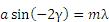
The specular reflection from the blazed grating is different from the flat surface due to the surface structure, as shown in Figure 5. The specular reflection, ![]() , from a blazed grating occurs at the blaze angle geometry. This angle is defined as being negative if it is on the same side of the grating surface normal as
, from a blazed grating occurs at the blaze angle geometry. This angle is defined as being negative if it is on the same side of the grating surface normal as ![]() . Performing some simple geometric conversions, one finds that
. Performing some simple geometric conversions, one finds that

(4)
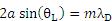
Figure 6 illustrates the specific case where ![]() = 0°, hence the incident light beam is perpendicular to the grating surface. In this case, the 0th order reflection also lies at 0°. Utilizing Eqs. 3 and 4, we can find the grating equation at twice the blaze angle:
= 0°, hence the incident light beam is perpendicular to the grating surface. In this case, the 0th order reflection also lies at 0°. Utilizing Eqs. 3 and 4, we can find the grating equation at twice the blaze angle:
(5)
Littrow Configuration for Reflective Gratings
The Littrow configuration refers to a specific geometry for blazed gratings and plays an important role in monochromators and spectrometers. It is the angle ![]() at which the grating efficiency is the highest. In this configuration, the angle of incidence of the incoming and diffracted light are the same,
at which the grating efficiency is the highest. In this configuration, the angle of incidence of the incoming and diffracted light are the same, ![]() =
= ![]() , and
, and ![]() > 0 so
> 0 so
(6)
Figure 7. Littrow Configuration
The Littrow configuration angle, ![]() , is dependent on the most intense order (
, is dependent on the most intense order (![]() = 1), the design wavelength,
= 1), the design wavelength, ![]() , and the grating spacing
, and the grating spacing ![]() . It is easily shown that the Littrow configuration angle,
. It is easily shown that the Littrow configuration angle, ![]() , is equal to the blaze angle,
, is equal to the blaze angle, ![]() , at the design wavelength. The Littrow / blaze angles for all Thorlabs' Blazed Gratings can be found in the grating specs tables.
, at the design wavelength. The Littrow / blaze angles for all Thorlabs' Blazed Gratings can be found in the grating specs tables.

(7)
It is easily observed that the wavelength dependent angular separation increases as the diffracted order increases for light of normal incidence (for ![]() = 0°,
= 0°, ![]() increases as
increases as ![]() increases). There are two main drawbacks for using a higher order diffraction pattern over a low order one: (1) a decrease in efficiency at higher orders and (2) a decrease in the free spectral range,
increases). There are two main drawbacks for using a higher order diffraction pattern over a low order one: (1) a decrease in efficiency at higher orders and (2) a decrease in the free spectral range, ![]() , defined as:
, defined as:

(8)
where ![]() is the central wavelength, and
is the central wavelength, and ![]() is the order.
is the order.
The first issue with using higher order diffraction patterns is solved by using an Echelle grating, which is a special type of ruled diffraction grating with an extremely high blaze angle and relatively low groove density. The high blaze angle is well suited for concentrating the energy in the higher order diffraction modes. The second issue is solved by using another optical element: grating, dispersive prism, or other dispersive optic, to sort the wavelengths/orders after the Echelle grating.
Figure 8. Volume Phase Holographic Grating
Volume Phase Holographic Transmission Gratings
Unlike traditional gratings, volume phase holographic (VPH) gratings do not have surface grooves. Instead, VPH gratings consist of a dichromated gelatin (DCG) film between two glass substrates. These VPH gratings are designed to reduce the periodic errors that can occur in blazed gratings. Surface gratings with high groove density also have an issue with polarization dependent loss. These unique transmission gratings deliver high first-order diffraction peak efficiency, low polarization dependence, and uniform performance over broad bandwidths.
The desired grating pattern is comprised of a repetitive series of lines separated by distance ![]() . The fringe planes for transmission gratings are perpendicular to the plane of the plate as seen in Figure 8, allowing any frequency of light to pass through the plate. Diffraction occurs as incoming light crosses through the DCG film. Therefore, the three major factors that determine performance are film thickness, bulk index (the average index of refraction between Bragg planes), and index modulation (the difference of index of refraction between the Bragg planes). The incident light enters the grating at an angle of
. The fringe planes for transmission gratings are perpendicular to the plane of the plate as seen in Figure 8, allowing any frequency of light to pass through the plate. Diffraction occurs as incoming light crosses through the DCG film. Therefore, the three major factors that determine performance are film thickness, bulk index (the average index of refraction between Bragg planes), and index modulation (the difference of index of refraction between the Bragg planes). The incident light enters the grating at an angle of ![]() , as measured from the surface normal. The light of order
, as measured from the surface normal. The light of order ![]() exiting the grating leaves at an angle of
exiting the grating leaves at an angle of ![]() , relative to the surface normal. The grating expression mentioned above can be used to calculate diffraction angles for volume phase holographic gratings since dispersion is based on the line density. The quality of the grating is determined by the fringe contrast, with a poor fringe contrast resulting in low efficiency or no grating at all.
, relative to the surface normal. The grating expression mentioned above can be used to calculate diffraction angles for volume phase holographic gratings since dispersion is based on the line density. The quality of the grating is determined by the fringe contrast, with a poor fringe contrast resulting in low efficiency or no grating at all.
The DCG film is taken through multiple quality control steps to ensure it performs up to standard and then cut into the desired size. The film is sealed between two glass covers to prevent degradation of the material. Since the DCG film is contained between two glass substrates, VPH gratings have high durability and long lifetimes, as well as easy maintenance compared to other gratings that can be easily damaged.

Figure 9. Holographic Grating
Holographic Surface Reflective Gratings
While blazed gratings offer extremely high efficiencies at the design wavelength, they suffer from periodic errors, such as ghosting, and relatively high amounts of scattered light, which could negatively affect sensitive measurements. Holographic gratings are designed specially to reduce or eliminate these errors. The drawback of holographic gratings compared to blazed gratings is reduced efficiency.
Holographic gratings are made from master gratings by similar processes to the ruled grating. The master holographic gratings are typically made by exposing photosensitive material to two interfering laser beams. The interference pattern is exposed in a periodic pattern on the surface, which can then be physically or chemically treated to expose a sinusoidal surface pattern. An example of a holographic grating is shown in Figure 9.
Please note that dispersion is based solely on the number of grooves per mm and not the shape of the grooves. Hence, the same grating equation can be used to calculate angles for holographic as well as ruled blazed gratings.
| Posted Comments: | |
Saúl Antonio Rosales
(posted 2023-11-22 18:18:40.74) Hello, I have found in my lab a grating that I think is removed from the actual list. The problem is that I can't see the serial number but only the end (.....-1850). It sais that the rule is 1800/mm, 500 nm blaze and a size of 12.7x12.7x6mm. With this information would it be possible to know the heights of the blazes, the period and material of the grating and the material of the substrate?
We are interested in doing simulations and we need that parameters or maybe the angle of the blaze.
Thanks in advance and kind regards!
Saúl cdolbashian
(posted 2023-11-29 02:11:55.0) Based on the specs as well as the information you provided, this looks like an obsolete component: GR13-1850. I have emailed you directly to discuss the additional questions you have presented. HB Shin
(posted 2023-05-30 13:54:42.473) Hello, I am curruntly using a 500 nm Blaze Wavelength Reflective Diffraction Grating
GR25-0605, and I wonder what function a Blaze Angle does. Since the equation m (Lambda) = d (sin theta1 + sin theta2) does not include the parameter,blaze angle, is the incident angle + / - symetrical such as 15 degree and -15 degree? Thanks, cdolbashian
(posted 2023-06-01 02:45:51.0) Thank you for reaching out to us with this inquiry. Notably the Blaze angle improves efficiency for specific wavelengths while also allowing the specular reflection to reflect with respect to the blaze angled surface, rather than the macroscopic surface normal. More information regarding this can be found in the tutorial tab above. I have also contacted you directly to discuss this further. user
(posted 2022-08-24 18:30:53.53) Hello, I want to find out the width of dispersion spectrum from a particular reflective diffraction grating.
On Thorlabs site, the dispersion values mentioned are in units of nm/m radians. However, the angular dispersion is calculated in terms of radians/nm. So, my doubt is whether these values are angular dispersion values.
Could you please explain, what are actually these dispersion values mentioned on the site. Markus G
(posted 2019-10-22 17:08:29.17) Hi - what is the flatness specification of the ruled grating (reflected wavefront flatness, or substrate flatness)?
-M nbayconich
(posted 2019-11-07 12:45:45.0) Thank you for contacting Thorlabs. While we do not specify flatness, we can state that it is typically λ/4 or better. I am unable to provide any data regarding the wave front error at this time. Alexandr Dibrov
(posted 2019-08-09 10:17:27.257) Dear Thorlabs,
is it possible to request a custom ruled grating with a particular groove angle?
Thanks!
Alex YLohia
(posted 2019-08-09 11:42:36.0) Hello Alex, custom items can be requested by emailing techsupport@thorlabs.com. We will reach out to you directly to discuss the possibility of offering this. |
Transmission Gratings
Thorlabs offers two types of transmission gratings: ruled and volume phase holographic. The ruled transmission gratings are created by scratching or etching a transparent substrate with a repetitive, parallel structure, creating areas where light can scatter. These gratings have a sawtooth diffraction profile and are made of epoxy and/or plastic imprints from a master copy, in a process called replication. Our volume phase holographic diffraction gratings consist of a dichromated gelatin (DCG) film between two glass substrates. These gratings have a sinusoidal wave diffraction pattern written on the DCG film using a laser setup. For more information, please refer to the Gratings Tutorial tab.
| Ruled Diffraction Gratings | ||
|---|---|---|
 |
UV | Thorlabs' ruled transmission gratings disperse incident light on the opposite side of the grating at a fixed angle. They are ruled and blazed for optimum efficiency in their respective wavelength range, are relatively polarization insensitive, and have an efficiency comparable to that of a reflection grating optimized for the same wavelength. They are ideal for applications that require fixed gratings such as spectrographs. |
| Visible | ||
| Near IR | ||
| UV Ruled Transmission Blazed Diffraction Gratings |
|---|
| Visible Ruled Transmission Blazed Diffraction Gratings |
|---|
| NIR Ruled Transmission Blazed Diffraction Gratings |
|---|
| Volume Phase Holographic Diffraction Gratings | |||
|---|---|---|---|
 |
Volume Phase Holographic | Thorlabs' volume phase holographic (VPH) gratings consist of a DCG film between two glass substrates. These unique transmission gratings are easy to maintain and deliver high first-order diffraction peak efficiency and uniform performance over broad bandwidths. | |
| Visible VPH Transmission Gratings |
|---|

| NIR VPH Transmission Gratings |
|---|


Reflective Gratings
Reflective grating master copies are made by depositing a metallic coating on an optic and ruling parallel grooves in the surface. Thorlabs' reflective gratings are made of epoxy and/or plastic imprints from a master copy, in a process called replication. In all cases, light is reflected off of the ruled surface at different angles corresponding to different orders and wavelengths. All of Thorlabs' ruled reflective diffraction gratings exhibit a sawtooth profile, also known as blazed, while our reflective holographic diffraction gratings exhibit a sinusoidal profile. For more information, please refer to the Gratings Tutorial tab.
| Ruled Diffraction Gratings | ||
|---|---|---|
 |
UV | Ruled gratings can achieve higher efficiencies than holographic gratings due to their blaze angles. They are ideal for applications centered near the blaze wavelength. Thorlabs offers replicated ruled diffraction gratings in a variety of sizes and blaze angles. |
| Visible | ||
| Near IR | ||
| Mid IR | ||
| UV Ruled Reflective Blazed Diffraction Gratings |
|---|
| Visible Ruled Reflective Blazed Diffraction Gratings |
|---|
| Near-IR Ruled Reflective Blazed Diffraction Gratings |
|---|
| Mid-IR Ruled Reflective Blazed Diffraction Gratings |
|---|
| Holographic Diffraction Gratings | |||
|---|---|---|---|
 |
Holographic | Holographic gratings have a low occurrence of periodic errors, which results in limited ghosting, unlike ruled gratings. The low stray light of these gratings makes them ideal for applications where the signal-to-noise ratio is critical, such as Raman Spectroscopy. | |
| Reflective Holographic Sinusoidal Diffraction Gratings |
|---|
| Echelle Diffraction Gratings | |||
|---|---|---|---|
 |
Echelle | Echelle gratings are low period gratings designed for use in high diffraction orders. They are generally used with a second grating or prism to separate overlapping diffracted orders. They are ideal for applications such as high-resolution spectroscopy. | |
| Echelle Ruled Blazed Diffraction Gratings |
|---|
Selecting a grating requires consideration of a number of factors, some of which are listed below:
Efficiency:
Ruled gratings generally have a higher efficiency than holographic gratings. Holographic grating tend to have a lower efficiency but a broader effective wavelength range. The efficiency of ruled gratings may be desirable in applications such as fluorescence excitation and other radiation-induced reactions.
Blaze Wavelength:
Ruled gratings have a sawtooth groove profile created by sequentially etching the surface of the grating substrate. As a result, they have a sharp peak efficiency around their blaze wavelength. Holographic gratings are harder to blaze, and tend to have a sinusoidal groove profile resulting in a less intense peak around the design wavelength. Applications centered around a narrow wavelength range could benefit from a ruled grating blazed at that wavelength.
Stray Light:
Due to a difference in how the grooves are made, holographic gratings have less stray light than ruled gratings. The grooves on a ruled grating are machined one at a time which results in a higher frequency of errors. Holographic gratings are made through a lithographic process, which generally creates smoother grating masters free of tool marks. Replicants made from these masters exhibit less stray light. Applications such as Raman spectroscopy, where signal-to-noise is critical, can benefit from the limited stray light of the holographic grating.
Resolving Power:
The resolving power of a grating is a measure of its ability to spatially separate two wavelengths. It is determined by applying the Rayleigh criteria to the diffraction maxima; two wavelengths are resolvable when the maxima of one wavelength coincides with the minima of the second wavelength. The chromatic resolving power (R) is defined by R = λ/Δλ = n*N, where Δλ is the resolvable wavelength difference, n is the diffraction order, and N is the number of grooves illuminated. Due to their low groove density, Echelle gratings provide high resolving power.
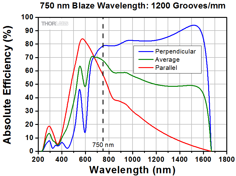
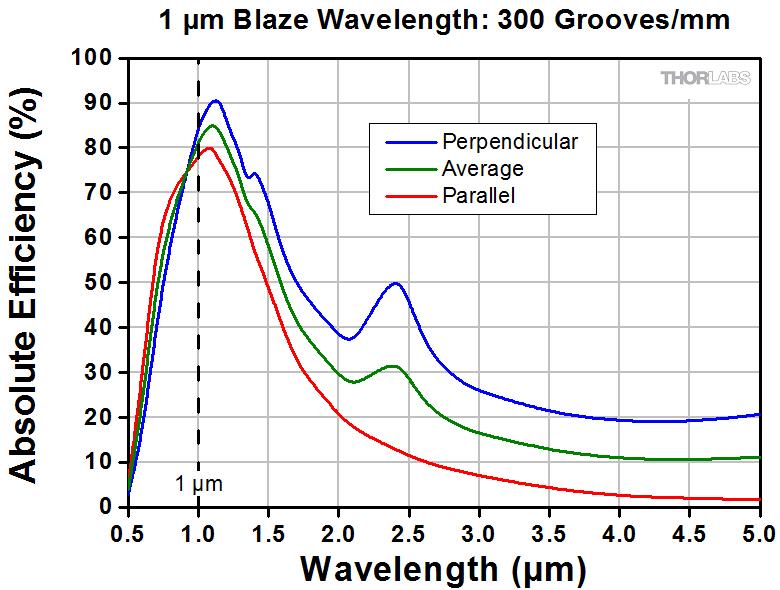
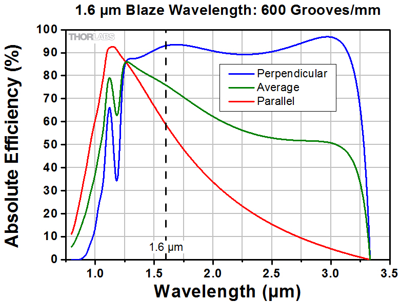
Polarization Dependence:
Surface gratings that have high groove densities also have an issue with polarization dependent loss, often with significantly lower efficiency when exposed to parallel- versus perpendicularly-polarized light. Volume phase holographic gratings are designed for applications that require low polarization dependent loss at higher spatial frequencies.
For further information about gratings and selecting the grating right for your application, please visit our Gratings Tutorial.
Caution for Gratings with Surface Grooves:
The surface of a diffraction grating with surface grooves can be easily damaged by fingerprints, aerosols, moisture or the slightest contact with any abrasive material. Gratings should only be handled when necessary and always held by the sides. Latex gloves or a similar protective covering should be worn to prevent oil from fingers from reaching the grating surface. Solvents will likely damage the grating's surface. No attempt should be made to clean a grating other than blowing off dust with clean, dry air or nitrogen. Scratches or other minor cosmetic imperfections on the surface of a grating do not usually affect performance and are not considered defects. Conversely, volume phase holographic gratings can be cleaned using standard optics cleaning procedures and have high durability.

 Zoom
Zoom| Item # | Dimensions (W x H x D) | Blaze Wavelength |
Grooves/mm | Blaze Angle | Dispersion | Efficiency Curvesa,b |
|---|---|---|---|---|---|---|
| GR25-1204 | 25 mm x 25 mm x 6 mm | 400 nm | 1200 | 13° 53' | 0.81 nm/mrad |  |
| GR50-1204 | 50 mm x 50 mm x 9.5 mm |

 Zoom
Zoom| Item # | Dimensions (W x H x D) | Blaze Wavelength |
Grooves/mm | Blaze Angle | Dispersion | Efficiency Curvesa,b |
|---|---|---|---|---|---|---|
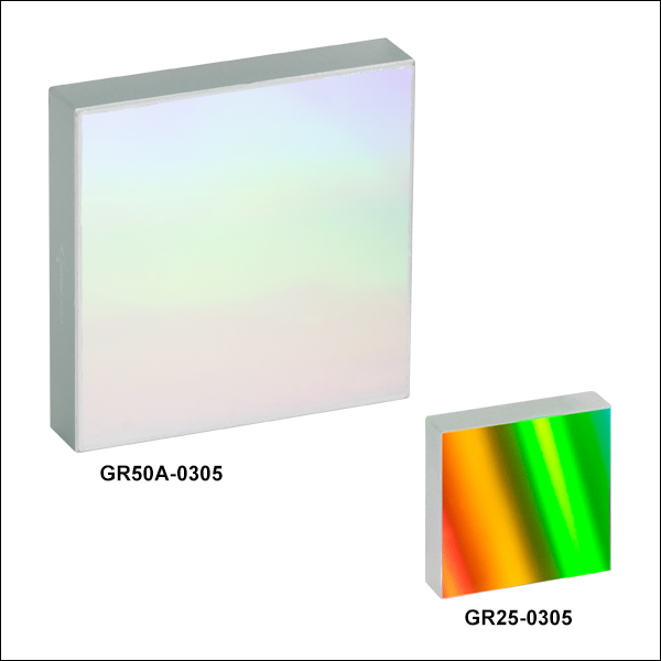
| GR13-0305 | 12.7 mm x 12.7 mm x 6 mm | 500 nm | 300 | 4° 18' | 3.32 nm/mrad |  |
| GR25-0305 | 25 mm x 25 mm x 6 mm | |||||
| GR50A-0305 | 50 mm x 50 mm x 9.5 mm |  |
||||
| GR13-0605 | 12.7 mm x 12.7 mm x 6 mm | 500 nm | 600 | 8° 37' | 1.65 nm/mrad |  |
| GR25-0605 | 25 mm x 25 mm x 6 mm | |||||
| GR50A-0605 | 50 mm x 50 mm x 9.5 mm |  |
||||
| GR13-1205 | 12.7 mm x 12.7 mm x 6 mm | 500 nm | 1200 | 17° 27' | 0.80 nm/mrad |  |
| GR25-1205 | 25 mm x 25 mm x 6 mm |