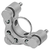
Polaris® Fixed Monolithic Mirror Mount for Laser System Design
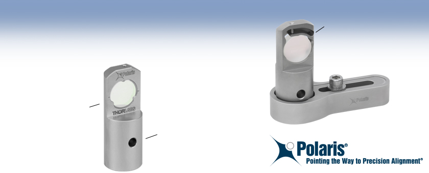
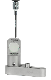
- Flexure Arm Provides Highly Stable Mirror Retention
- Heat Treating Minimizes Temperature-Dependent Hysteresis
- M6 x 1.0 Tap and Holes for Ø2 mm Alignment Pins in Base
- Optic Face Centered on Post Axis
Heat-Treated, Monolithic Stainless Steel
Precision Alignment Bore
POLARIS-19S50/M
For Ø19 mm Mirrors
(Mirror Sold Separately)
FRONT
BACK
Flexure Arm Optic Retention
POLARIS-CA1
Non-Bridging
Clamping Arm

Please Wait
Features
- Ultra-Stable Monolithic Design is Ideal for OEM Applications
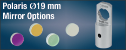
- Fixed Mount Designed for Ø19 mm Mirrors (See Ø19 mm Mirrors Tab for Our Selection)
- Extensive Testing Guarantees <2 μrad Deviation After 12.5 °C Temperature Cycling
(See the Test Data Tab for Details) - Optic Face Centered on the Post Axis Simplifies Alignment and Allows Pure Rotation
- Precision Ø6 mm Bore for Angle Tuning and Alignment
- 50 mm Beam Height (Custom Options Available; See Below)
- Two Ø2 mm Alignment Pin Holes in the Base for Precision Mounting (Dowel Pins Not Included)
- Bottom-Located M6 x 1.0 Tap (Custom Options Available; See Below)
- Non-Bridging Mounting Solution Prevents Table Distortion and Optical Misalignment
(See the Clamping Arm Data Tab for Details) - Fabricated from Heat-Treated Stainless Steel
- Materials are Vacuum Compatible to 10-9 Torr at 25 °C with Proper Bake Out
Monolithic Construction
Polaris® Fixed Monolithic Mirror Mounts are the ultimate solution for OEM applications requiring stringent long-term alignment stability. These mounts are fabricated from a single piece of heat-treated stainless steel, ensuring high stability by minimizing the number of interfaces within the assembly and effectively reducing component creep over time.
Designed for Ø19 mm Optics
The Polaris fixed mirror mount is designed to securely hold 6 mm thick, Ø19 mm mirrors. The Ø19 mm optic size allows for a small Ø1" (Ø25.4 mm) footprint on the optical table, making these mounts ideal when trying to reduce the size of a system or create space in constrained setups. Thorlabs stocks a wide variety of Ø19 mm mirrors for use with this mount, including broadband dielectric, laser line, metallic, and blank mirrors. Please see the Ø19 mm Mirrors tab for our selection.
Click to Enlarge
The flexure arm used in the Polaris mount provides stable optic retention with minimal wavefront distortion. Please see the Test Data tab for test results.
Flexure Arm for Optic Retention
A long flexure arm and setscrew combination provides temperature-independent retention of the optic, unlike nylon-tipped setscrews, which are sensitive to temperature fluctuations. This mounting mechanism, along with the provided three points of axial contact, makes it so the optic does not need to be glued into the Polaris mount to achieve maximum stability and minimum wavefront distortion.
Polaris lens cells are precision machined to achieve a fit that will provide optimum beam pointing stability performance over changing environmental conditions such as temperature changes, transportation shock and vibration. These mounts have had their performance tested and verified with Ø19 mm optics that have a diameter tolerance of up to +0/-0.1 mm, so this tolerance range is recommended for optimal performance. Note that the mounts are not intended for use with optics that have an outer diameter tolerance greater than zero.
Mounting Features
These Polaris mirror mounts are equipped with two Ø2 mm alignment pin holes for direct, precision mounting within a custom or OEM laser system. A centered, bottom-located M6 x 1.0 tap is also included. Versions with custom alignment pin hole locations, a 1/4"-20 tap, or no tap are available by using our Polaris configurator below.
In combination with our cage rods, the Ø6 mm +0.025/-0.000 mm precision bore in the Polaris fixed mount allows for the alignment of multiple mounts along a common optical axis, or for fine angle tuning when used with our Polaris clamping arms, sold below. Please see the Usage Tips tab for more information and other usage recommendations.
Non-Bridging Clamping Arms
The Polaris clamping arms (sold separately) are the ideal mounting solution for our monolithic Polaris mount. Their design strongly reduces the gap, or “bridge,” that traditionally results between the back of a standard clamping fork and a Ø1" pedestal post base. When tightening the post to the table, this bridge causes the mounting screw to pull up on the mounting platform, permanently deforming it and disturbing the alignment of nearby optical components. In contrast, these clamping arms have a ±0.001" (±0.02 mm) flat top and bottom that helps to reinforce the board when the clamping arm is mounted, greatly reducing or eliminating platform deformation. For more information on the effects of bridging, please see the Clamping Arm Data tab.
Cleanroom and Vacuum Compatibility
The POLARIS-19S50/M mirror mount and Polaris clamping arms sold on this page are designed to be compatible with cleanroom and vacuum applications. See the Specs tab and the Design Features tab for more information.
| Item # | POLARIS-19S50/M | |||||
|---|---|---|---|---|---|---|
| Optic Sizea | Ø19 mm | |||||
| Optic Thickness (Min) | 2 mm (0.08") | |||||
| Beam Heightb,c | 50 mm (1.97") | |||||
| Clear Aperture | Ø17.1 mm (0.68") | |||||
| Beam Deviationd After Thermal Cycling | <2 μrad | |||||
| Recommended Optic Mounting Torque | 5.5 - 6.0 oz-in for 6 mm Thick Optics | |||||
| Mounting Tape | M6 x 1.0 Tap | |||||
| Alignment Pin Holes | Two Ø2 mm Holes for DIN 7-m6 Ground Dowel Pins (Not Included) Around Mounting Tap (See Drawing Below) |
|||||
| Vacuum Compatibilityf | 10-9 Torr at 25 °C with Proper Bake Out; 10-5 Torr at 25 °C without Bake Out Grease Vapor Pressure: 10-13 Torr at 20 °C ,10-5 Torr at 200 °C Epoxy Meets Low Outgassing Standards NASA ASTM E595, Telcordia GR-1221 |
|||||
| Operating Temperature Range | -30 to 200 °C | |||||
| Weight | 0.16 kg (0.35 lbs) | |||||

POLARIS-19S50/M Mechanical Drawing
Polaris® Mirror Mounts Test Data
Polaris Fixed Monolithic Mirror Mounts have undergone extensive testing to ensure high-quality performance.
Optical Distortion Testing Using a ZYGO Phase-Shifting Interferometer
Stress, strain, and displacement are all typical mounting forces experienced by an optic in any mount. Stress is the sum of all internal forces acting on a deformable object, strain is a measurement of deformation, and displacement is a measurement of how the stress and strain affect the shape and position of the object. Minimizing this effect is crucial; any distortion to the optic is transmitted to the light that is reflected from it.
A ZYGO Phase-Shifting Interferometer was used to determine the recommended torque for retaining the optic while minimizing wavefront distortion. The results of these tests can be found below. Based on these tests, we recommend a torque of 5.5 - 6 oz-in for the flexure arm. These values provide a typical wavefront distortion of 0.1 waves.
| Torque (oz-in) | Push Out Force (lbf)a | Wavefront Distortion (Peak to Valley)b |
|---|---|---|
| 5 | <3.88 | 0.059λ to 0.102λ |
| 5.5 | 3.88 | 0.067λ to 0.103λ |
| 6 | 7.09 | 0.085λ to 0.136λ |
| 6.5 | 7.93 | 0.090λ to 0.152λ |
| 7 | 9.51 | 0.126λ to 0.172λ |
| 7.5 | >9.51 | 0.125λ to 0.216λ |
Procedure:
A BB07-E02 Ø19 mm Broadband Dielectric Mirror was installed into a POLARIS-19S50/M Fixed Mount using the setscrew to clamp down the flexure arm. The Zygo interferometer aperture diameter was set to 80% for these measurements to stay within the clear aperture of the front face of the mount. Measurement increments of 0.5 oz-in were used, and the mirror was checked for push-out force at each torque value to ensure optic retention. The values in the table above represent the peak-to-valley distortion across the entire optic, illustrating the worst-case scenario; the center of the optic shows significantly better distortion effects.
Results:
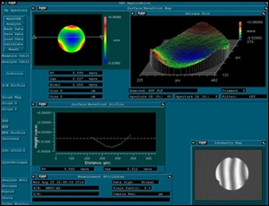
As seen in the table to the right and the images below, the peak-to-valley wavefront distortion was found to remain at approximately 0.1λ when 5.5 - 6 oz-in of torque was applied to the setscrew.
Click to Enlarge
5 oz-in of Torque
Click to Enlarge
5.5 oz-in of Torque
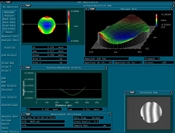
Click to Enlarge
6 oz-in of Torque
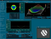
Click to Enlarge
6.5 oz-in of Torque
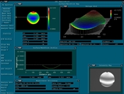
Click to Enlarge
7 oz-in of Torque
Positional Repeatability After Thermal Shock
The Polaris was first secured to a stainless steel rigid platform in a temperature-controlled environment. The mirror is held using the stainless steel flexure arm, not glued; see the Usage Tips tab for additional mounting recommendations. A beam from an independently temperature-stabilized laser diode was reflected by the mirror onto a position sensing detector.
Purpose: This testing was done to determine how reliably the mount returns the mirror, without hysteresis, to its initial position. These measurements show that the alignment of the optical system is unaffected by the temperature shock.
Procedure: The temperature of each mirror mount tested was raised to 37.5 °C. The elevated temperature was maintained for 60 minutes (soak time). Then the temperature of the mirror mount was returned to the starting temperature. Each POLARIS-19S50/M was clamped to the table using the POLARIS-CA1 Clamping Arm. The results of these tests are shown below.
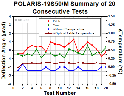
Results: As can be seen in the plots below, when the Polaris mounts were returned to their initial temperature, the angular position (both pitch and yaw) of the mirrors returned to within 2 µrad of its initial position. The performance of the Polaris was tested further by subjecting the mount to repeated temperature change cycles. After each cycle, the mirror’s position reliably returned to within 2 µrad of its initial position.
Conclusions: The Polaris Fixed Monolithic Mirror Mount is a high-quality, ultra-stable mount that will reliably return a mirror to its original position after cycling through a temperature change. As a result, the Polaris mount is ideal for use in applications that require long-term alignment stability.

Click to Enlarge
The plot above shows the pitch and yaw measured by a position-sensing detector before, while, and after a thermal shock was applied to the POLARIS-19S50/M mount.
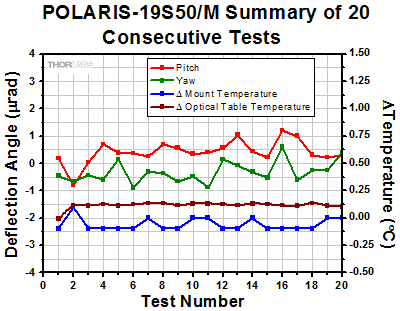
Click to Enlarge
Test Series 2
The plot above shows the final angular position of a second POLARIS-19S50/M for 20 consecutive thermal shock tests. The change in temperature is the difference between the starting temperature and the temperature at the end of the test and includes factors such as the variation in room temperature. This shows the repeatability of the tests.
Click to Enlarge
Test Series 1
The plot above shows the final angular position of the POLARIS-19S50/M for 20 consecutive thermal shock tests. The change in temperature is the difference between the starting temperature and the temperature at the end of the test and includes factors such as the variation in room temperature.
Optical Distortion Testing Using a ZYGO Phase-Shifting Interferometer
Stress, strain, and displacement are all typical mounting forces experienced by an optic in any mount. Stress is the sum of all internal forces acting on a deformable object, strain is a measurement of deformation, and displacement is a measurement of how the stress and strain affect the shape and position of the object. Minimizing this effect is crucial; any distortion to the optic is transmitted to the light that is reflected from it.
A ZYGO Phase-Shifting Interferometer was used to determine the recommended torque for retaining the optic while minimizing wavefront distortion. The results of these tests can be found below. Based on these tests, we recommend a torque of 5.5 - 6 oz-in for the flexure arm. These values provide a typical wavefront distortion of 0.1 waves.
| POLARIS-19S50/M Wavefront Distortion Test Results | ||
|---|---|---|
| Torque (oz-in) | Push Out Force (lbF)a | Wavefront Distortion (Peak to Valley)b |
| 5 | - | 0.059λ to 0.102λ |
| 5.5 | 3.88 | 0.067λ to 0.103λ |
| 6 | 7.09 | 0.085λ to 0.136λ |
| 6.5 | 7.93 | 0.090λ to 0.152λ |
| 7 | 9.51 | 0.126λ to 0.172λ |
| 7.5 | - | 0.125λ to 0.216λ |
Polaris® Clamping Arm Testing
Various tests were conducted to show the performance of our Polaris Clamping Arms. Many of the results were then compared to other industry-standard products that were put to the same test to show the high-quality performance of the Polaris clamping arms when used with our Ø1" Posts for Polaris Mounts. Click the links below for more information about a specific test.
- Laser Platform Deformation
- Determine the extent to which an industry-standard clamping fork deforms or permanently damages a stainless steel rigid platform, and whether or not the Polaris clamping arm improves upon or prevents this damage.
- Post and Platform Mounting Torque
- Determine the ideal amount of clamping torque necessary to (1) securely mount a Ø1" post within the flexure clamp bore of a Polaris clamping arm and (2) to secure the clamping arm into a laser system. This data was then compared to the closest competitor's industry-standard clamping fork design.
- Post Breaking Torque
- Determine the amount of torque needed to break a Ø1" PLS-P150 post loose from a Polaris clamping arm that was holding it.
- Post Deflection
- Determine how much a Polaris post will temporarily and permanently deflect when it is mounted within a Polaris clamping arm and a force is applied.
Click to Enlarge
Figure 1: Industry-Standard Clamping Fork Beam Drift
Laser Platform Deformation
Purpose: This testing was performed to determine the extent to which an industry-standard clamping fork deforms or permanently damages a stainless steel rigid platform and whether or not the Polaris clamping arm improves upon or prevents this damage. The POLARIS-CA1 clamping arm was used for this test; similar results can be expected for all other Polaris clamping arms. These measurements show that the Polaris clamping arm significantly reduces temporary deformation to the surface and that no permanent damage was measured during our extensive tests.
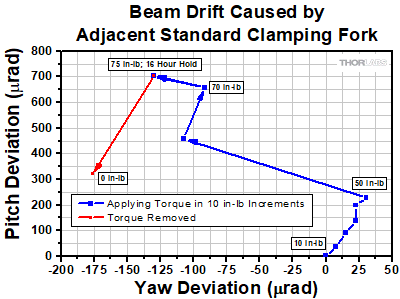
Procedure: An industry-standard clamping fork was mounted in close proximity to another optical element that was used for aligning a beam onto a position detector. As the clamping fork was mounted to the platform at various torque values (blue data sets in Figure 1 and Figure 2), the yaw and pitch deviation of the beam was measured at the detector. At 75 in-lbs of torque, the fork was left attached to the platform for 16 hours. After the 16 hour period, the fork was released from the table and the final beam deviation was recorded (red data sets in Figure 1 and Figure 2). This procedure was repeated for the POLARIS-CA1 clamping arm. Each test was performed at different regions of the platform. A final deviation of anything but zero indicated that the surface had been permanently deformed.
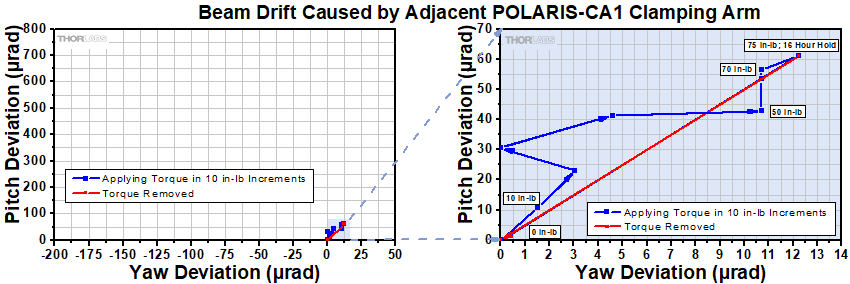
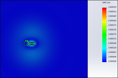
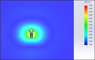
Results: As can be seen in the plots below and to the right, the industry-standard clamping fork created a yaw and pitch deviation of 131 µrad and 702 µrad, respectively, at 75 in-lbs, while the POLARIS-CA1 clamping arm created a yaw and pitch deviation of 12.2 µrad and 61 µrad, respectively, at 75 in-lbs. The POLARIS-CA1 also returned the beam to its initial position when released after a 16 hour hold. The industry-standard clamping fork did not return the beam to its original position; the beam stayed at a yaw and pitch deviation of 176 µrad and 321 µrad, respectively. The simulaton results shown in Figures 3 and 4 show the amount of deformation created by an industry-standard clamping fork compared to the POLARIS-CA1 clamping arm.
Conclusion: The POLARIS-CA1 clamping arm caused no permanent damage to the optical mounting surface and it significantly minimized the deformation to the platform surface when it was in use (see Figures 3 and 4). The industry-standard clamping fork was shown to permanently damage the laser platform after use, and to create severe deformation to the surface while in use. As a result, the Polaris clamping arm is ideal for use in systems requiring long term stability and consistent, precision alignments.
Click for Details
Figure 2: Note that the distortion caused by the Polaris clamping arm at 75 in-lb is comparable to the distortion caused by the industry-standard clamping fork at 10 in-lb.
Click to Enlarge
Figure 4: In comparison, the POLARIS-CA1 clamping arm causes minimal deformations around the fork. Note that the scale on this second plot has been magnified by 10X in order to make these minimal deformations visible.
Click to Enlarge
Figure 3: The industry-standard clamping fork causes large deformations over a significant area surrounding the fork.
Mounting Torque
Purpose: This testing was performed to determine the ideal amount of clamping torque necessary to (1) securely mount a Ø1" post within the flexure clamp bore of a Polaris clamping arm and (2) to secure the clamping arm into a laser system. This data was then compared to the closest competitor's industry-standard clamping fork design.
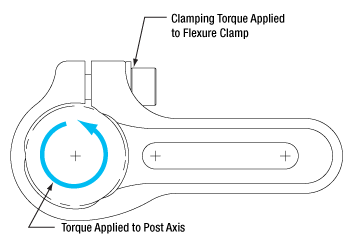
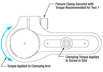
Procedure: The POLARIS-CA1(/M) was used to hold a standard Ø1" post. The clamping arm was first bolted to a stainless steel rigid platform, and the 1/4"-20 (M6 x 1.0) screw that controls the flexure clamp was actuated to specific torque values. At each torque value, the post had a rotational torque applied around its axis until it moved within the clamping arm's bore. The torque value at the moment directly before this "movement point" is called the holding torque (see plots below). Using similar methods, a mounting slot test was performed to find the ideal torque needed to secure the clamping arm to the laser platform. The mounting slot test was repeated for the POLARIS-SCA1 to determine if the slot size affects the torque measurements.
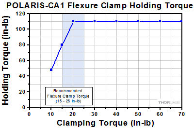
Results Summary: For optimal performance, the flexure clamping screw of an imperial clamping arm should be tightened with 15 to 25 in-lb of torque and the flexure clamping screw of a metric clamping arm with 1.75 to 3 N•m of torque. When mounting to a table or platform, we recommend using 40 to 65 in-lb of torque for an imperial clamping arm and 4.75 to 7 N•m of torque for a metric clamping arm. Please see below for the detailed results.
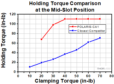
Conclusion: The Polaris clamping arm was shown to be the ideal solution for securely mounting a component to a laser system platform. At only 20 in-lb and 40 in-lb of clamping torque for the flexure clamp and mounting slot respectively, a post mounted in an imperial clamping arm can withstand up to 110 in-lb of opposing torque (corresponding torques for a metric clamping arm is 2.4, 4.8, and 12.4 N•m, respectively). This performance is superior to the closest competitor's industry-standard clamping fork, which needs a clamping torque of 70 in-lb in the close position to reach a similar value of 100 in-lb. As demonstrated in the Laser Platform Deformation test above, minimizing the amount of torque applied to the mounting surface prevents permanent damage.
Test 1 Results: Flexure Clamp Holding Torque
As can be seen in Figure 6 below, at 20 in-lbs of clamping torque, the POLARIS-CA1 provided 110 in-lb of holding torque. For reference, 110 in-lbs of torque is enough to damage the threading on a 1/4"-20 stainless steel cap screw. The corresponding torque for the POLARIS-CA1/M is a holding torque of 12.4 N•m at a clamping torque of 2.4 N•m. The torque values for imperial and metric clamps are not a direct conversion due to an efficiency difference between 1/4"-20 and M6 x 1.0 screws. The efficiency of M6 screws is about 5% less than that of 1/4"-20 screws due to differences in diameter and pitch. All imperial Polaris clamping arms will perform similarly to the POLARIS-CA1, while all metric Polaris clamping arms will perform similarly to the POLARIS-CA1/M.
Click to Enlarge
Click for POLARIS-CA1/M Flexure Clamp Holding Torque Results
Figure 6: Results from Test 1. The blue shaded region indicates the recommended flexure clamp torque. All imperial Polaris clamping arms will perform similarly to the POLARIS-CA1, while all metric Polaris clamping arms will perform similarly to the POLARIS-CA1/M.
Click to Enlarge
Figure 5: Holding torque is measured at the moment directly before the "movement point" of the post being torqued.
Test 2 Results: Mounting Slot Holding Torque
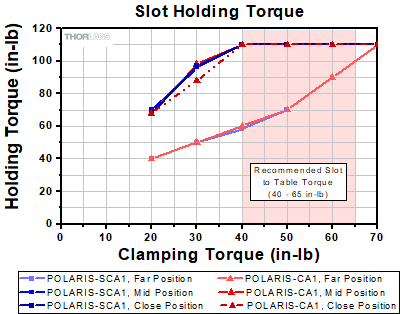
The recommended torque for the mounting slot varies depending on the position of the 1/4"-20 (M6 x 1.0) cap screw within the slot (i.e. close to the post, midway along the slot, or far from the post). Figure 8 compares the slot holding torque of the POLARIS-SCA1 and POLARIS-CA1, and shows that the slot size does not affect the torque measurements. The recommended slot holding torque is 40 - 65 in-lb for imperial clamping arms, while for metric clamping arms the slot holding torque is 4.75 - 7 N•m. Similar to the Test 1 results, the torque values for imperial and metric clamps are not a direct conversion due to an efficiency difference between 1/4"-20 and M6 screws. The efficiency of M6 screws is about 5% less than that of 1/4"-20 screws due to differences in diameter and pitch.
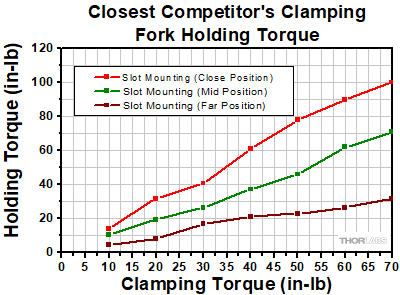
The performance of the closest competitor's clamping fork also depends on the position of the 1/4"-20 (M6 x 1.0) cap screw in the slot. However, as shown in Firgure 9, the performance of the fork degrades sharply at the mid and far positions. At the far position, the best holding torque achieved is 32 in-lb with a clamping torque of 70 in-lb. As shown in Figure 10, at 40 in-lbs of clamping torque, the POLARIS-CA1 provided 110 in-lb of holding torque, while at the same clamping torque, the competitor's fork only achieved a holding torque of 38 in-lbs.
Click to Enlarge
Click for POLARIS-CA1/M Slot Holding Torque Results
Figure 8: Results from Test 2. The red shaded region indicates the recommended torque to secure the clamping arm to the optical table. This comparison between the POLARIS-SCA1 and POLARIS-CA1 shows that the slot size does not affect the slot holding torque. All imperial Polaris clamping arms will perform similarly to the POLARIS-CA1, while all metric Polaris clamping arms will perform similarly to the POLARIS-CA1/M.
Click to Enlarge
Figure 7: Holding torque is measured at the moment directly before the "movement point" of the clamping arm being torqued.
Click to Enlarge
Figure 9: Results from Test 2 on a competitor's clamping fork. See Figure 8 for results from POLARIS-CA1(/M).
Click to Enlarge
Figure 10: Comparison of Test 2 results for POLARIS-CA1 and a competitor's clamping fork, both at the middle position in the moutning slot.
Click to Enlarge
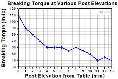
Figure 12: Breaking force recorded with the post mounted at 14 different heights above the platform. This shows that upwards of 110 in-lb of torque is required to loosen the PLS-P150 post from the clamping arm when the post is in contact with the work surface.
Click to Enlarge
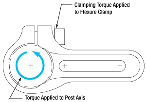
Figure 11: Breaking torque is defined as the moment directly after the "movement point" of the post being torqued.
Breaking Torque
Purpose: This test was performed to determine the amount of torque needed to break a Ø1" PLS-P150 post loose from a Polaris clamping arm. The POLARIS-CA1 clamping arm was used for this test; similar results can be expected for all other Polaris clamping arms.
This test was repeated at various heights above the work surface.
Procedure: A PLS-P150 1.5" long, Ø1" post was secured with 25 in-lb of torque at various heights within a POLARIS-CA1 clamping arm, which was then secured to a custom laser platform. As shown in Figure 11, torque was then applied to the post axis until it reached its "movement point." This torque was recorded as the breaking torque.
Results: As can be seen in Figure 12, upwards of 110 N•m of torque is required to loosen the PLS-P150 post from the clamping arm. When the post was raised off of the platform by 13 mm, a torque of about 40 N•m was still required to loosen the post. It is important to note here that the clamping arm is only 15.2 mm (0.60") thick.
Conclusion: The PLS-P150 post and clamping arm create an extremely stable system that is resistant to large forces acting upon it, even when the post is raised off of the platform by 13 mm. This is ideal for any custom or OEM system that requires components to stay aligned when faced with vibrations caused by shipping and installation.
Post Deflection

Click to Enlarge
Figure 13: A force was applied to the PLS-P150 post 0.90" (22.9 mm) above the edge of the clamping arm with the post mounted at nine different heights off of the mounting surface. At each mounting height, the post deflection was measured during and after the application of the force.
Purpose: This test was performed to determine the amount of temporary and permanent deflection of a Ø1" post for Polaris mirror mounts secured in a Polaris clamping arm when a force is applied. The POLARIS-CA1 clamping arm was used for this test; similar results can be expected for all other Polaris clamping arms.
Procedure: A PLS-P150 1.5" long, Ø1" post was secured with 25 in-lb of torque at various heights within a POLARIS-CA1 clamping arm, which was then secured to a custom laser platform. A force was then applied to the center of the post, 0.90" (22.9 mm) above the top edge of the clamping arm (see Figure 13 for details). This test was conducted with the post mounted at nine different heights off of the platform, ranging from 0 mm to 8 mm. The amount of deflection was measured while the force was being applied (Figure 14) and after the force was removed (Figure 15).
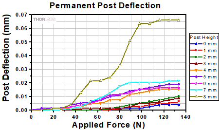
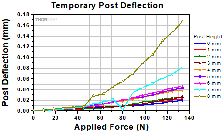
Results: Figure 14 shows that the PLS-P150 post will deflect by <0.01 mm as a force of ≤40 N is applied for any post height ≤8 mm, and by <0.17 mm as a force of ≤133 N is applied for any post height ≤8 mm. These values show the temporary deflection of the post while the force is being applied. For all of the post mounting heights tested (0 to 8 mm), an applied force ≤35 N caused a permanent deflection of the post smaller than 0.005 mm, measured after the force was removed. For the two lowest mounting heights, 0 and 2 mm, no permanent deflection was measured for applied forces of 45 N or less. At 133 N, the maximum force applied, permanent deflection for all tested mounting heights remained below 0.07 mm.
Conclusion: Our Ø1" posts and POLARIS-CA1 clamping arm create an extremly stable system that is able to resist large forces acting upon it. This is ideal for any custom or OEM system that requires components to stay aligned when faced with vibrations caused by shipping and installation.
Click to Enlarge
Figure 15: Post deflection measured after the applied force was removed. The measurement was repeated with the bottom of the post positioned 0 to 8 mm above of the mounting surface (see the Procedure section for details). For post-to-mounting-surface distances of 2 mm or less, no permanent deflection was measured if the force was ≤45 N.
Click to Enlarge
Figure 14: Post deflection measured while a force was applied to the post. The measurement was repeated with the bottom of the post positioned 0 to 8 mm above of the mounting surface (see the Procedure section for details).
Hours of extensive research, multiple design efforts using sophisticated design tools, and months of rigorous testing went into choosing the best components to provide an ideal solution for experiments requiring ultra-stable performance from a fixed mirror mount.
Thermal Hysteresis
The temperature in most labs is not constant due to factors such as air conditioning, the number of people in the room, and the operating states of equipment. Thus, it is necessary that all mounts used in an alignment-sensitive optical setup be designed to minimize any thermally induced alignment effects. Thermal effects can be minimized by choosing materials with a low coefficient of thermal expansion (CTE), like stainless steel. However, even mounts made from a material with a low CTE do not typically return the mirror to its initial position when the initial temperature is restored. The monolithic body of the Polaris fixed mirror mount is heat treated, thus removing internal stresses that can cause a temperature-dependent hysteresis. As a result, the alignment of the optical system will be restored when the temperature of the mirror mount is returned to the initial temperature.
Optic Retention
The method by which the mirror is secured in the mount is another important design factor for the Polaris; this Polaris mount offers excellent performance without the use of adhesives. Instead, it uses a flexure arm, which is part of the single-piece design, that is pressed onto the edge of the mirror using a setscrew. Setscrews, when used by themselves to hold an optic, tend to move as the temperature changes. In contrast, the holding force provided by the monolithic, stainless steel flexure arm is sufficient to keep the mirror locked into place regardless of the ambient temperature.
Click to Enlarge
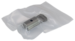
All Polaris Mounts are Shipped Inside Two Vacuum Bag Layers
Cleanroom and Vacuum Compatibility
The POLARIS-19S50/M is designed to be compatible with cleanroom and vacuum chamber applications. It is chemically cleaned using the Carpenter AAA passivation method to remove sulfur, iron, and contaminants from the surface. After passivation, it is assembled in a clean environment and then double vacuum bagged to eliminate contamination when transported into a cleanroom. When operating at pressures below 10-5 Torr, we highly recommend using an appropriate bake out procedure prior to installing the mount in order to minimize contamination caused by outgassing.
Cleanroom-Compatible Packaging
Each vacuum-compatible Polaris mount is packaged within two vacuum bag layers after assembly in a clean environment, as seen in the image to the right. The vacuum-tight fit minimizes rubbing against the bag, preventing the introduction of bag material shavings that would contaminate the clean mount. In the vacuum-sealing process, moisture-containing air is drawn out of the packaging. This eliminates unwanted reactions on the surface of the mount without the need for desiccant materials.
The vacuum bags protect the mount from contamination by air or dust during transport and storage, and the double-vacuum bag configuration allows for a straightforward and effective cleanroom entry procedure. The outer bag can be removed outside of the cleanroom, allowing the contaminant-free inner bag to be placed into a clean container and transferred into the cleanroom while retaining the benefits of vacuum-bag packaging. Inside the cleanroom, the mount can be removed from the inner bag when ready for use.
Click to Enlarge
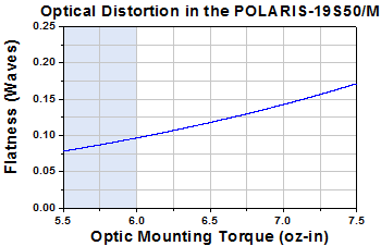
At zero torque, the sample mirror's flatness was λ/20 over the clear aperture (λ = 633 nm). The shaded region in this plot denotes the recommended optic mounting torque for a 6 mm thick optic.
Through thermal changes and vibrations, the Polaris fixed mirror mount is designed to provide years of use. Below are some usage tips to ensure that the mount provides optimal performance.
Monolithic Design
The Polaris fixed mirror mount is fabricated from a single piece of stainless steel because of this material's relatively low coefficient of thermal expansion (CTE), thus reducing the magnitude of temperature-induced beam misalignments. Being constructed from a single piece of stainless steel also ensures high stability by minimizing the number of interfaces within the assembly, effectively reducing component creep over time. When mounting, we recommend using components fabricated from the same material, such as our POLARIS-CA1(/M) Clamping Arm, in order to match thermal expansion coefficients.
Ø6 mm Precision Bore
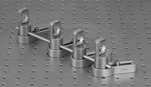
A Ø6 mm alignment bore is located 20 mm from the base at the horizontal center of the mount. This bore, which is precision machined to a tolerance of +0.025 mm/-0.000 mm, can be used for fine angle tuning of the mount when used with our Polaris clamping arms, as shown in the image to the right below. It can also be used with our Ø6 mm cage rods for aligning multiple mounts, as shown in the image below. Please note: We recommend only using our cage rods with the precision bore, as large amounts of torque applied with another tool could damage the bore.
Click to Enlarge
The Ø6 mm Precision Bore can be Used with a Cage Rod to Align Two or More Fixed Polaris Mounts
Click to Enlarge
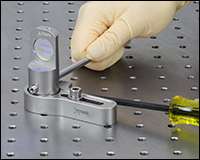
A cage rod can be used for fine angle tuning in combination with the precision bore and a POLARIS-CA1 Clamping Arm (all items
sold separately).
Optic Mounting
Since an optic is prone to movement within its mounting bore, all optics should be mounted before installing the Polaris into the setup to ensure accurate mounting that will minimize misalignment effects. We recommend using a torque wrench when installing an optic in the Polaris mounts. Over torquing the flexure-arm optic retainer can result in dramatic surface distortions. The graph to the right shows surface distortions that result from increasing torque values delivered by the TD24 torque wrench for a POLARIS-19S50/M with a Ø19 mm, 6 mm thick BB07-E02 mirror mounted in it. The test was stopped once the distortion was greater than 0.175 waves.
Extensive testing was also performed to see the performance when the flexure clamp is hand tightened without a torque wrench. The results of this test can be found here. When hand-tightening the flexure arm to retain the optic, sufficient torque should be applied to feel the contact between the arm and optic. Once that is achieved, the optic will be secured within the cell. Though this method is repeatable and will maintain low optic distortion, we recommend using a torque wrench for the best results.
Do not actuate the flexure arm without an optic installed. The POLARIS-19S50/M mount is calibrated to minimize mirror distortion at 5.5 - 6 oz-in of optic mounting torque; if the flexure arm is forced beyond the point when it would normally contact the optic, this calibration will no longer be valid.
Installing the post in the clamping arm before attaching the clamping arm to the table can create a bridge, which can alter optical alignment and damage the surface of the optical table or breadboard.
Mount as Close to the Platform Surface as Possible
To minimize the impact of vibrations and temperature changes, it is recommended that your setup has as low of a profile as possible. Using short posts will reduce the vertical translation caused by temperature variations and will minimize any movements caused by vibrations. They can be stably mounted directly to a laser platform using our Polaris clamping arms. Although Ø1" posts can be used to increase the height of the mount, it is not recommended due to the increase in component creep over time. Custom fixed Polaris mounts can be ordered with beam heights ranging from 25 mm to 150 mm (1" to 6").
Attach the Clamping Arm to the Table First
The video to the left shows the optimal way to mount a post and clamping arm to an optical table. Note that the first step is to secure the clamping arm to the table. If, instead, the monolithic mount is first attached to the clamping fork and then the pair is attached to the table, a bridge may result, thereby altering the optical alignment and potentially damaging the surface of the optical table or breadboard (see Overview tab for details).
Polish and Clean the Points of Contact
We highly recommend that the points of contact between the post and the table are clean and free of raised scratches or defects. For best results, we recommend using a polishing stone to clean the platform's surface and a LFG1P polishing pad for the bottom of the post as well as the bottom of clamping arm. Any hand oils that are on the mounting surfaces will significantly reduce holding forces. It is recommended that all the mounting contact surfaces on the clamping arm, table top, and post be cleaned with methanol, acetone, or alcohol to remove all unwanted oils.
Ø19 mm Optics
The POLARIS-19S50/M is designed to securely hold 6 mm thick, Ø19 mm mirrors. This mirror size allows the mounts to maintain a Ø1" footprint while maximizing the clear aperture of the mirror face. The flexure arm and setscrew combination provide three points of axial contact to minimize distortion as well as increasing the holding force and stability of the optic.
Thorlabs stocks a wide variety of Ø19 mm mirrors for use with our POLARIS-19S50/M Fixed Monolithic Mirror Mount. This includes broadboad dielectric, laser line, metallic, and blank mirrors. See the table below for all of our stocked options.
| Item # | Wavelength | Coating Type | Reflectance | Reflectance Curvesa (Click for Plot) |
|---|---|---|---|---|
| Broadband Dielectric Mirrors | ||||
| BB07-E01 | 350 - 400 nm | Broadband Dielectric | Ravg > 99% for 350 - 400 nm | |
| BB07-E02 | 400 - 750 nm | Broadband Dielectric | Ravg > 99% for 400 - 750 nm | |
| BB07-E02Pb | 400 - 750 nm | Broadband Dielectric (Backside Polished) |
Ravg > 99% for 400 - 750 nm | |
| BB07-E03 | 750 - 1100 nm | Broadband Dielectric | Ravg > 99% for 750 - 1100 nm | |
| BB07-E03Pc | 750 - 1100 nm | Broadband Dielectric (Backside Polished) |
Ravg > 99% for 750 - 1100 nm | |
| BB07-E04 | 1280 - 1600 nm | Broadband Dielectric | Ravg > 99% for 1280 - 1600 nm | |
| Laser Line Mirrors | ||||
| NB07-K04 | 262 - 266 nm | Nd:YAG Laser Line (4th Harmonic) |
Ravg > 99.0% for 262 - 266 nm | |
| NB07-K05 | 300 - 308 nm | Ar-Ion Laser Line | 0° to 45° AOI: Ravg > 99.5% (S-Pol), Ravg > 98.0% (P-Pol) for 300 - 308 nm | |
| NB07-K07 | 333 - 364 nm | Ar-Ion Laser Line | 0° AOI: R > 99.5% (Unpolarized) at 352 nm 45° AOI: R > 99.0% (S-Pol), R > 98.7% (P-Pol) at 352 nm |
|
| NB07-K08 | 349 - 355 nm | Nd:YAG Laser Line (3rd Harmonic) |
Ravg > 99.5% for 349 - 355 nm | |
| NB07-K10 | 458 - 528 nm | Ar-Ion Laser Line | 0° to 45° AOI: Ravg > 99.0% (S-Pol), Ravg > 99.0% (P-Pol) for 458 - 528 nm | 6° and 45° AOI |
| NB07-J11 | 520 - 647 nm | Kr-Ion Laser Line | Ravg > 99.7% for 520 - 647 nm | |
| NB07-K12 | 524 - 532 nm | Nd:YAG Laser Line (2nd Harmonic) |
Ravg > 99.0% for 524 - 532 nm | |
| NB07-K13 | 532 nm and 1064 nm | Nd:YAG Laser Line (Fundamental and 2nd Harmonic) |
R > 98% at 532 nm R > 99% at 1064 nm |
532 nm 1064 nm |
| NB07-K14 | 1047 - 1064 nm | Nd:YAG Laser Line (Fundamental) |
Ravg > 99.5% for 1047 - 1064 nm | |
| Metallic Mirrors | ||||
| PF07-03-F01 | 250 - 450 nm | UV Enhanced Aluminum | Ravg > 90% for 250 - 450 nm | 12° AOI 45° AOI |
| PF07-03-G01 | 450 nm - 20 µm | Protected Aluminum | Ravg > 90% for 450 nm - 2 µm Ravg > 95% for 2 - 20 µm |
12° AOI 45° AOI |
| PF07-03-P01 | 450 nm - 20 µm | Protected Silver | Ravg > 97.5% for 450 nm - 2 µm Ravg > 96% for 2 - 20 µm |
12° AOI 45° AOI |
| PF07-03-P01Pd | 450 nm - 20 µm | Protected Silver (Backside Polished) |
Ravg > 96% for 400 - 700 nm Ravg > 97.5% for 700 nm - 2 µm |
12° AOI 45° AOI |
| PF07-03-M01 | 800 nm - 20 µm | Protected Gold | Ravg > 96% for 800 nm - 20 µm | 12° AOI 45° AOI |
| Mirror Blanks | ||||
| PF07-03 | N/A | Mirror Blank | N/A | N/A |
| Posted Comments: | |
seungeun_oh
(posted 2017-10-06 02:45:16.393) Do you make the monolithic mirror mount without the hole for mirror? I want to glue a prism mirror on the vertical surface. nbayconich
(posted 2017-10-06 05:44:38.0) Thank you for contacting Thorlabs. We can provide this as a custom service. I will reach out to you directly about our custom capabilities. user
(posted 2016-10-11 14:59:54.42) I couldn't understand the large deformations due to "bridging" that you modeled. I measured table deformation using a Thor optics table, Thor pedestal, Thor clamping fork. Even with 10 ft-lb(!) of torque on the screw, the maximum table deviation was 0.0001". The fork however, flexed quite a bit. I think the modeling isn't valid. Also, why is this "bridging" a problem? tfrisch
(posted 2016-10-25 08:57:48.0) Hello, thank you for contacting Thorlabs. The bridging is an effect by which the top skin of a breadboard or optical table will be pulled up by the screw between the clamp's points of contacts with the table. The reason this is undesirable is that it may tilt other post mounted optics nearby. In some applications where beam steering is critical (such as coupling into single mode fiber), bridging can affect performance significantly. However, in some applications, the tolerance for deviations of the beam is much looser and may not be noticed. If you would like more details on our testing, please contact us at TechSupport@Thorlabs.com. tmorgus
(posted 2015-09-11 14:14:33.953) While we don't currently have a 0.5" version in design it is something that Thorlabs could offer. One of the primary goals of the Polaris line of mounts is stability. 19mm was the largest diameter optic that could be held in a monolithic mount that met our performance criteria when starting from a 1" diameter cylinder. I'll send you an email as I would be interested in your thoughts on expanding the product line. Sincerely, Tyler, Thorlabs Mechanics Business Unit j.fischer
(posted 2015-09-11 10:48:26.807) Are there any plans for a version designed for 0.5" Optics?
What is the reason for the 19mm choice? |
Thorlabs offers several different general varieties of Polaris mounts, including kinematic side optic retention, SM-threaded, low optic distortion, piezo-actuated, vertical drive, and glue-in optic mounts, a fixed monolithic mirror mount and fixed optic mounts, XY translation mounts, 5-axis kinematic mount, and a kinematic platform mount. Refer to the tables below for our complete line of Polaris mounts, grouped by mount type, optic bore size, and then arranged by optic retention method and adjuster type (or intended application in the case of fixed mounts). We also offer a line of accessories that have been specifically designed for use with our Polaris mounts; these are listed in the table to the lower right. Note that the tables below list Item # suffixes that omit the "POLARIS" prefix for brevity. Click the photos below for details.
| Polaris Mount Adjuster Types | |||||
|---|---|---|---|---|---|
| Side Hole | Hex | Adjuster Knobs | Adjuster Lock Nuts |
Piezo Adjusters | Vertical-Drive Adjusters |
 |
 |
 |
 |
 |
 |
| Polaris Kinematic Mounts for Round Optics | ||||
|---|---|---|---|---|
| Optic Retention Method | Side Lock | SM Threaded | Low Distortion | Glue-In |
| Ø1/2" Optics | ||||
| 2 Side Hole Adjusters | - | - | - | -K05C4 -K05G4 |
| 2 Hex Adjusters | -K05S1 | -K05T1 | -K05F1 | - |
| 2 Adjusters with Lock Nuts | -K05S2 | -K05T2 | -K05F2 | - |
| 2 Piezoelectric Adjusters | -K05P2 | - | - | - |
| 2 Vertical Adjusters | -K05VS2 -K05VS2L |
- | - | - |
| 3 Hex Adjusters | -K05 | - | - | - |
| 3 Adjusters with Lock Nuts | - | -K05T6 | -K05F6 | - |
| 3 Adjuster Knobs (Tip/Tilt/Z) & 2 Hex Adjusters (X/Y) |
- | -K05XY | - | - |
| Ø19 mm (3/4") Optics | ||||
| 2 Side Hole Adjusters | -K19S4 | - | -K19F4/M | -K19G4 |
| Ø25 mm Optics | ||||
| 2 Side Hole Adjusters | -K25S4/M | - | -K25F4/M | - |
| Ø1" Optics | ||||
| 2 Side Hole Adjusters | -K1S4 | - | - | -K1C4 -K1G4 |
| 2 Hex Adjusters | -K1E2 -K1-2AH |
-K1T2 | -K1F2 | - |
| 2 Adjuster Knobs | - | -K1T1 | -K1F1 | - |
| 2 Piezoelectric Adjusters | -K1S2P | - | - | - |
| 2 Vertical Adjusters | -K1VS2 -K1VS2L |
- | - | - |
| 3 Side Hole Adjuster | -K1S5 | - | - | - |
| 3 Hex Adjusters | -K1E3 -K1-H |
-K1T3 | - | - |
| 3 Adjuster Knobs | -K1E -K1 |
-K1T | -K1F | - |
| 3 Piezoelectric Adjusters | -K1S3P | - | - | - |
| 3 Adjuster Knobs (Tip/Tilt/Z) & 2 Hex Adjusters (X/Y) |
- | -K1XY | - | - |
| Optic Retention Method | Side Lock | SM Threaded | Low Distortion | Glue-In |
| Ø1.5" Optics | ||||
| 2 Side Hole Adjusters | -K15S4 | - | -K15F4 | - |
| 2 Vertical Adjusters | -K15VS2 -K15VS2L |
- | - | - |
| 3 Adjuster Knobs (Tip/Tilt/Z) & 2 Hex Adjusters (X/Y) |
- | -K15XY | - | - |
| Ø50 mm Optics | ||||
| 2 Side Hole Adjusters | -K50S4/M | - | -K50F4/M | - |
| Ø2" Optics | ||||
| 2 Hex Adjusters | -K2S2 | -K2T2 | -K2F2 | - |
| 2 Adjuster Knobs | -K2S1 | -K2T1 | -K2F1 | - |
| 2 Piezoelectric Adjusters | -K2S2P | - | - | - |
| 2 Vertical Adjusters | -K2VS2 -K2VS2L |
- | - | - |
| 3 Hex Adjusters | -K2S3 | -K2T3 | -K2F3 | - |
| 3 Adjuster Knobs | -K2 | -K2T | -K2F | - |
| Ø3" Optics | ||||
| 2 Side Hole Adjusters | -K3S4 | - | - | - |
| 3 Side Hole Adjusters | -K3S5 | - | - | - |
| Ø4" Optics | ||||
| 2 Side Hole Adjusters | - | - | -K4F4 | - |
| Ø6" Optics | ||||
| 2 Side Hole Adjusters | - | - | -K6F4 | - |
| Polaris XY Translation Mounts for Round Optics | ||
|---|---|---|
| Optic Retention Method | SM Threaded | Representative Photos |
| Ø1/2" Optics |   |
|
| 2 Hex Adjusters (X/Y) | -05XY | |
| 3 Adjuster Knobs (Tip/Tilt/Z) & 2 Hex Adjusters (X/Y) |
-K05XY | |
| Ø1" Optics | ||
| 2 Hex Adjusters (X/Y) | -1XY | |
| 3 Adjuster Knobs (Tip/Tilt/Z) & 2 Hex Adjusters (X/Y) |
-K1XY | |
| Ø1.5" Optics | ||
| 2 Hex Adjusters (X/Y) & 3 Adjuster Knobs (Tip/Tilt/Z) |
-K15XY | |
| Polaris Fixed Mounts for Round Optics | ||||||
|---|---|---|---|---|---|---|
| Optic Retention Method | Side Lock | Low Distortion |
Glue-In | Representative Photos |
||
| Ø1/2" Optics |     |
|||||
| Optimized for Mirrors | - | -B05F | -C05G | |||
| Optimized for Beamsplitters | -B05S | - | -B05G | |||
| Optimized for Lenses | - | - | -L05G | |||
| Ø19 mm (Ø3/4") Optics | ||||||
| Optimized for Mirrors | -19S50/M | - | - | |||
| Ø1" Optics | ||||||
| Optimized for Mirrors | - | -B1F | -C1G | |||
| Optimized for Beamsplitters | -B1S | - | -B1G | |||
| Optimized for Lenses | - | - | -L1G | |||
| Ø2" Optics | ||||||
| Optimized for Mirrors | - | -B2F | -C2G | |||
| Optimized for Beamsplitters | -B2S | - | - | |||
| Polaris Kinematic 1.8" x 1.8" Platform Mount | ||
|---|---|---|
| Optomech Retention Method | Tapped Holes & Counterbores |
 |
| 2 Adjuster Knobs | -K1M4(/M) | |
| Accessories for Polaris Mounts | |
|---|---|
| Description | Representative Photos |
| Ø1" Posts for Polaris Mounts |  |
| Polaris Non-Bridging Clamping Arms |  |
| Polaris 45° Mounting Adapter |  |

| Specificationsa | ||||||
|---|---|---|---|---|---|---|
| Optic Size | Ø19 mm | |||||
| Optic Thickness (Min) | 2 mm (0.08") | |||||
| Beam Heightb, c | 50 mm (1.97") | |||||
| Recommended Optic Mounting Torque | 5.5 - 6.0 oz-in for 6 mm Thick Optics | |||||
| Mounting Tapd | M6 x 1.0 Tap | |||||
| Alignment Pin Holes | Two Ø2 mm Holes for DIN 7-m6 Ground Dowel Pins (Not Included) Around Mounting Tap (See Drawing in Specs Tab) |
|||||
| Operating Temperature Range | -30 to 200 °C | |||||

Click to Enlarge
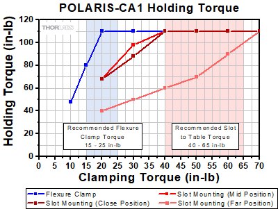
Click for POLARIS-CA1/M Holding Torque Results*
The Polaris clamping fork design has undergone extensive testing to ensure high-quality performance. See the Clamping Arm Data tab for more details.
*It is important to note that the 1/4"-20 and M6 x 1.0 clamping torque values have been adjusted to provide the same clamping post and table forces. Also note that the maximum recommended tightening torque for an 18-8 stainless steel screw is 75.2 in-lbs for a 1/4"-20 screw and 8.8 N-m for an M6 x 1.0 screw. Higher mounting torques can cause the screw to fail.
Click to Enlarge
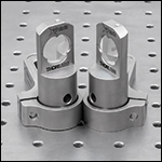
The arm can be mounted with either flat surface in contact with the table, allowing for compact setups.
Click to Enlarge
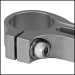
Side-Located 1/4"-20 (M6) Screw Actuates Clamping Bore
- 3-Point Contact Bore with Flexure Clamping Mechanism
- For Ø1" Monolithic Polaris Mount and Ø1" Posts for Polaris Mounts (See Table Below)
- 0.60" Bore Depth Supports Height Adjustments Up to 0.25"
- Allows Posts to be Rotated 360°
- 0.75" (19.1 mm) or 1.30" (33.0 mm) Slot for 1/4"-20 (M6) Cap Screw
- Heat-Treated, Stress-Relieved Stainless Steel Provides Large Clamping Force
- Design Supports Left- and Right-Handed Orientations (See Lower Left Image)
- High Stability Ideal for Use with Our Polaris Mirror Mounts
- Vacuum Compatible to 10-9 Torr at 25 °C with Proper Bake Out
- ±0.001" (±0.02 mm) Surface Flatness
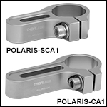
The Polaris® Clamping Arms are the ideal solution for stably mounting our Ø1" Monolithic Polaris Mount or Ø1" Posts for Polaris Mounts. Each clamping arm, which is machined from heat-treated, stress-relieved stainless steel bar stock, provides extremely high holding forces with minimal torquing of the mounting screws (see the graph to the right).
The flat, non-bridging top and bottom surfaces of each clamping arm allow it to be used with either side in contact with an optical table or other mounting surface. This feature allows the clamp to be positioned in left- or right-handed orientations and optical components to be placed in near contact to one another while minimizing the footprint (see the image to the left). On each side of the arm, a relief cut around the slot protects the ±0.001" (±0.02 mm) flat surface from any marring due to the screw and washer, allowing for more stable mounting.
Two choices of slot length, 0.75" (19.1 mm) or 1.30" (33.0 mm), provide flexibility for applications such as tight laser cavity setups. The clamping arms available here are designed to only hold Ø1" posts. They are not compatible with Ø25 mm posts; the bore diameter is too large and will not contact the post when clamping. For Ø25 mm post systems, we also offer clamping arms with Ø25 mm mounting bores.
Non-Bridging Design: Industry Standard Clamping Fork
vs. Polaris Clamping Arm
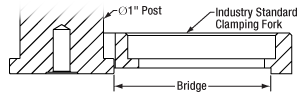
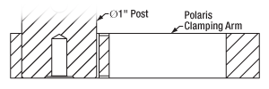
Industry standard clamping forks are designed with a bridge, as shown in Figure 1, for clamping to pedestal-style posts or post holders. This design will slightly damage the laser platform during each use by pulling up the part of the platform located under the bridge. The Polaris clamping arm, as shown in Figure 2, is designed with a flat top and bottom to eliminate this problem.
Click to Enlarge
Figure 1: A Bridge is Created When an Industry Standard Clamping Fork is Used with a Pedestal Post
Click to Enlarge
Figure 2: The Polaris Clamping Arm Eliminates the Bridge Created by an Industry Standard Clamping Fork
The flexure clamp, shown in the photo to the left, is actuated using a side-located 1/4"-20 (M6 x 1.0) cap screw and allows a post to be rotated 360° about its center. As the flexure clamp and mounting slot are secured with separate screws, the position of the fork and the rotational alignment of the post can be adjusted independently. While best performance is achieved with full post engagement, the 0.60" (15.2 mm) thick mounting bore supports up to 0.25" of post height adjustment.
The Polaris clamping fork design has undergone extensive testing to ensure high-quality performance; see the graph to the upper right. For optimal performance, we recommend tightening the flexure clamping screw of an imperial clamping arm with 15 to 25 in-lb of torque and the flexure clamping screw of a metric clamping arm with 1.75 to 3 N•m of torque. When mounting to a table or platform, we recommend using 40 to 65 in-lb of torque for an imperial clamping arm and 4.75 to 7 N•m of torque for a metric clamping arm. Please note that the values for imperial and metric clamps are not a direct conversion due to an efficiency difference between 1/4"-20 and M6 x 1.0 screws. The efficiency of M6 x 1.0 screws is about 5% less than that of 1/4"-20 screws due to differences in diameter and pitch. For best results, use the maximum recommended torques from each range. These torque values can be dialed in using a torque driver.
| Item # | Compatible Post Size |
Clamping Screw |
Slot Length | Footprint |
|---|---|---|---|---|
| POLARIS-SCA1 | Ø1" (25.4 mm) |
1/4"-20 (3/16" Hex) |
0.75" (19.1 mm) |
2.78" x 1.60" (70.5 mm x 40.6 mm) |
| POLARIS-CA1 | 1.30" (33.0 mm) |
3.33" x 1.60" (84.5 mm x 40.6 mm) |
||
| POLARIS-SCA1/M | M6 x 1.0 (5 mm Hex) |
0.75" (19.1 mm) |
2.78" x 1.60" (70.5 mm x 40.6 mm) |
|
| POLARIS-CA1/M | 1.30" (33.0 mm) |
3.33" x 1.60" (84.5 mm x 40.6 mm) |
 Products Home



 Zoom
Zoom Polaris OEM Fixed Mirror Mount