 Products Home / Optomechanical Components / Optical Post Assemblies / Bases / Table Clamps / Universal Base Plates
Universal Base Plates
- Center-Located Slot Allows for Rotation and Translation
- Array of Tapped and Counterbored Holes Allow for a
Variety of Mounting Options - Provide Mounting Holes in Any Orientation on the
Optical Table
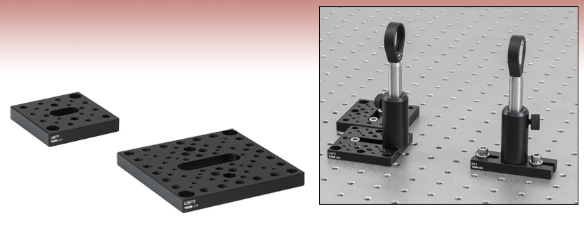
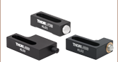
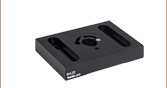
UBP3
3.50" x 3.50" x 0.38",
30 mm and 60 mm Cage System Mounting
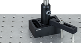
The UBP2 Base Plate can be used to roughly adjust the spacing
between the lenses in a telescope setup.
UBP1
2.00" x 2.00" x 0.38",
16 mm Cage System Mounting


Please Wait
Features
- Six Variants Offered with a Wide Variety of Mounting Options
- Central Counterbored Slot Allows for Rotation and Translation
- Models Available for 16 mm, 30 mm, and 60 mm Cage System Mounting
Our UBP Series Universal Base Plates increase the flexibility of any optical setup by providing mounting holes in virtually any orientation on an optical table or breadboard. This freedom allows users to mount various components or stages in a wide array of orientations outside of what is dictated by the standard 1" (25.0 mm) hole pattern. The counterbores in these plates also allow users to adapt metric components to an imperial optical table and vice versa.
Refer to the table below for specifications and detailed mounting options, including mechanical drawings. Each base plate has a counterbored slot in the center for mounting flexibility at any rotation, as well as counterbored holes at the corners for mounting to compatible breadboards. Cage system compatibility is offered via 4-40 tapped holes with the appropriate spacings.
| Item # | Counterbored Slot Size |
Threaded Mounting Holes |
Counterbored Mounting Holes |
Cage Sytem Compatibility (via 4-40 Threaded Holes) |
Dimensions (W x L x H) | Mechanical Drawings |
|---|---|---|---|---|---|---|
| UBP1 | #8 0.38" Long |
8-32 (10 Places) 4-40 (8 Places) |
#8 (6 Places) | 16 mm Cage Systems | 2.00" x 2.00" x 0.38" | |
| UBP1/M | M4 8.8 mm Long |
M4 x 0.7 (10 Places) M3 x 0.5 (4 Places) 4-40 (4 Places) |
M4 (6 Places) | 50.0 mm x 50.0 mm x 9.5 mm | ||
| UBP2 | 1/4" 1.25" Long |
1/4"-20 (6 Places) 8-32 (16 Places) 4-40 (4 Places) |
1/4" (4 Places) #8 (4 Places) |
30 mm Cage Systems | 2.50" x 2.50" x 0.38" | |
| UBP2/M | M6 31.8 mm Long |
M6 x 1.0 (6 Places) M4 x 0.7 (16 Places) 4-40 (4 Places) |
M6 (4 Places) M4 (4 Places) |
65.0 mm x 65.0 mm x 10.0 mm | ||
| UBP3 | 1/4" 1.25" Long |
1/4"-20 (24 Places) 8-32 (24 Places) 6-32 (6 Places) 4-40 (8 Places) |
1/4" (4 Places) #8 (4 Places) |
30 mm Cage Systems 60 mm Cage Systems |
3.50" x 3.50" x 0.38" | |
| UBP3/M | M6 29.8 mm Long |
M6 x 1.0 (24 Places) M4 x 0.7 (30 Places) 4-40 (8 Places) |
M6 (4 Places) M4 (4 Places) |
90.0 mm x 90.0 mm x 10.0 mm |
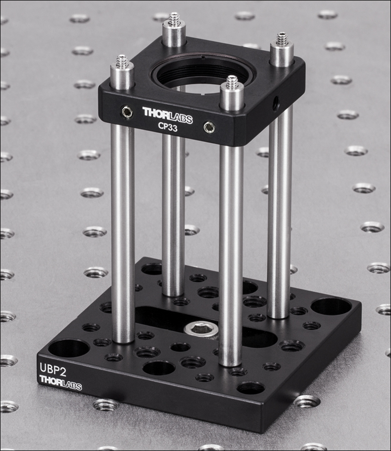
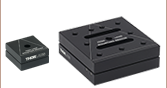
Click to Enlarge
The UBP2 plate can be used to vertically mount a 30 mm cage system (ER3 rods and CP33 cage plate shown). The centrally located slot allows mounting of components outside of the standard hole pattern.
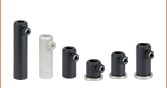
Cage System Overview
The Cage Assembly System provides a convenient way to construct large optomechanical systems with an established line of precision-machined building blocks designed for high flexibility and accurate alignment.
16 mm, 30 mm, and 60 mm Cage System Standards
Thorlabs offers three standards defined by the center-to-center spacing of the cage assembly rods (see image below). The 16 mm cage, 30 mm cage, and 60 mm cage standards are designed to accommodate Ø1/2", Ø1", and Ø2" optics, respectively. Specialized cage plates that allow smaller optics to be directly inserted into our larger cage systems are also available.
Standard Threads
The flexibility of our Cage Assembly System stems from well-defined mounting and thread standards designed to directly interface with a wide range of specialized products. The three most prevalent thread standards are our SM05 Series (0.535"-40 thread), SM1 Series (1.035"-40 thread), and SM2 Series (2.035"-40 thread), all of which were defined to house the industry's most common optic sizes. Essential building blocks, such as our popular lens tubes, directly interface to these standards.
An example of the standard cage plate measurements determining cage system compatibility.
| Standard Cage System Measurements | |||
|---|---|---|---|
| Cage System | 16 mm | 30 mm | 60 mm |
| Thread Series | SM05 | SM1 | SM2 |
| Rod to Rod Spacing | 16 mm (0.63") | 30 mm (1.18") | 60 mm (2.36") |
| Total Length | 25 mm (0.98") | 41 mm (1.60") | 71.1 mm (2.80") |
| Cage Components | ||
|---|---|---|
| Cage Rods | 16 mm | These rods are used to connect cage plates, optic mounts, and other components in the cage system. The SR Series Cage Rods are compatible with our 16 mm cage systems, while the 30 mm and 60 mm cage systems use ER Series Cage Rods. |
| 30 mm | ||
| 60 mm | ||
| Cage Plates | 16 mm | These serve as the basic building blocks for a cage system. They may have SM-threaded central bores, smooth bores sized for industry standard optics or to accommodate the outer profile of our SM Series Lens Tubes, or specialized bores for other components such as our FiberPorts. |
| 30 mm | ||
| 60 mm | ||
| Optic Mounts | 16 mm | Thorlabs offers fixed, kinematic, rotation, and translation mounts specifically designed for our Cage Systems. |
| 30 mm | ||
| 60 mm | ||
| Cage Cubes | 16 mm | These cubes are useful for housing larger optical components, such as prisms or mirrors, or optics that need to sit at an angle to the beam path, such as beamsplitters. Our cage cubes are available empty or with pre-mounted optics. |
| 30 mm | ||
| 60 mm | ||
| Replacement Setscrews | Replacement setscrews are offered for our 16 mm (SS4B013, SS4B025, and SS4B038) and 30 mm (SS4MS5 and SS4MS4) cage systems products. | |
| Post and Breadboard Mounts and Adapters | Mounting options for cage systems can be found on our Cage System Construction pages. Cage Systems can be mounted either parallel or perpendicular to the table surface. | |
| Size Adapters | Cage System Size Adapters can be used to integrate components from different cage system and threading standards. | |
| Specialized Components | Thorlabs also produces specialized cage components, such as Filter Wheels, a HeNe Laser Mount, and a FiberPort Cage Plate Adapter, allowing a wide range of our products to be integrated into cage-mounted optical systems. Explore our Cage Systems Visual Navigation Guide to see the full range of Thorlabs' cage components. | |
| Posted Comments: | |
cottsb
(posted 2015-03-05 18:12:15.91) This baseplate changed my life! cdaly
(posted 2015-03-10 03:18:21.0) Response from Chris at Thorlabs: Thank you for the feedback. We are glad to hear it. |