 Products Home
Customizable Optogenetics Kits
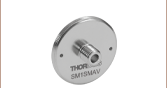
- Complete Fiber Optics Kit for Optogenetics with Optional Component Substitution
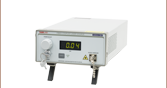
- 470 nm LED Light Source
- Ø1.25 mm or Ø2.5 mm Ferrule Cannulae with Ø200 μm or Ø400 μm Fiber Core
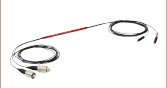
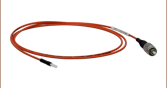
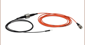
- Standard and Rotary Joint Patch Cables
Kit with Rotary Joint Patch Cable, Ø200 µm Core Fiber, and Ø2.5 mm Ferrules


Please Wait
| Kit # | Kit 1 | Kit 2 | Kit 3 | Kit 4 | ||||
|---|---|---|---|---|---|---|---|---|
| Light Source | M470L5 Mounted 470 nm LED (Fiber-Coupled 590 nm Substitution Available) | |||||||
| LED Driver | LEDD1B | |||||||
| Fiber Core Size | Ø200 µm | Ø400 µm | ||||||
| Cannula Ferrule Size |
Ø2.5 mm | Ø1.25 mm | Ø2.5 mm | Ø1.25 mm | ||||
| Patch Cable | Standard | Rotary Joint | Standard | Rotary Joint | Standard | Rotary Joint | Standard | Rotary Joint |
| Cannula Output Powera |
2.6 mW | 1.9 mW | 4.5 mW | 2.8 mW | 17.9 mW | 7.7 mW | 18.8 mW | 9.09 mW |
| Variation in Output Powerb |
N/A | ±7% | N/A | ±7% | N/A | ±7% | N/A | ±7% |
Features
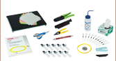
- Complete Fiber Optics Setup Including LED, Patch Cable, Cannulae, and Accessories
- Flexible Component Substitution
- Stainless Steel Ferrules and Fiber Cores in Two Sizes:
- Ø1.25 mm Ferrules (Ø200 or Ø400µm Core Fiber)
- Ø2.5 mm Ferrules (Ø200 or Ø400 µm Core Fiber)
- Standard Lightweight Patch Cable with Rotary Joint Patch Cable Option
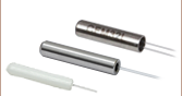
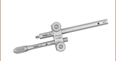
- Cannula Holders for Implantation with Stereotaxic Equipment
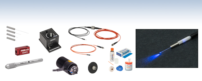
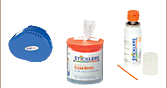
- Fiber Cleaving and Cleaning Essentials
- Cleaved Cannulae of Various Lengths with Uncleaved Cannulae Kit Option
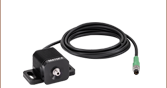
- Cannula Connectors
- 1 Quick-Release Interconnect
- 5 Mating Sleeves
Thorlabs' optogenetics equipment is available in complete, ready-to-use kits. Our optogenetics kits include a 470 nm Mounted LED with
Each component in these kits can be removed or substituted for items more applicable to the individual needs of the experiment. See below for the most relevant kit, and the OG Selection Guide for
For more particular experimental needs, Thorlabs offers custom fiber components for optogenetics. For more information, contact Tech Support.
Optogenetics Product Family for In Vivo Applications
Thorlabs offers a wide variety of products designed to support in vivo optogenetics applications. Please visit the OG Selection Guide tab above to see a full listing of available products for different applications.
| Thorlabs Optogenetics Equipment Selection Guide | |||||||||
|---|---|---|---|---|---|---|---|---|---|
| Fiber Optic Cannulae |
Rotary Joint Patch Cables |
1x2 Rotary Joint Splitter |
Standard Patch Cables |
Interconnect and Mating Sleeves |
Multimode Fiber Couplers |
LED Light Sources | Laser Light Source | Customizable Kits | |
Optogenetics Specifications
| Kit # | Kit 1 | Kit 2 | Kit 3 | Kit 4 | |||||
|---|---|---|---|---|---|---|---|---|---|
| Light Source | M470L5 470 nm Mounted LED | ||||||||
| LED Driver | LEDD1B | ||||||||
| Fiber Type | FT200EMT | FT400EMT | |||||||
| Fiber Core Size | Ø200 µm | Ø400 µm | |||||||
| Fiber NA | 0.39 | 0.39 | |||||||
| Fiber Wavelength Range (Click for Plot) |
400 - 2200 nm | 400 - 2200 nm | |||||||
| Cannula Ferrule Size | Ø2.5 mm | Ø1.25 mm | Ø2.5 mm | Ø1.25 mm | |||||
| Patch Cable | M77L01 (1 m Long) |
RJPSF2 (3 m Long with Rotary Joint) |
M89L01 (1 m Long) |
RJPSL2 (3 m Long with Rotary Joint) |
M79L01 (1 m Long) |
RJPSF4 (3 m Long with Rotary Joint) |
M98L01 (1 m Long) |
RJPSL4 (3 m Long with Rotary Joint) |
|
| Cannula Interconnects and Mating Sleeves |
1 x ADAF2 Interconnect 1 x ADAF1-5 Mating Sleeves (5 Pack) |
1 x ADAL3 Interconnect 1 x ADAL1-5 Mating Sleeves (5 Pack) |
1 x ADAF2 Interconnect 1 x ADAF1-5 Mating Sleeves (5 Pack) |
1 x ADAL3 Interconnect 1 x ADAL1-5 Mating Sleeves (5 Pack) |
|||||
| Cannulae | 5 x CFM12L02 (2 mm) 5 x CFM12L05 (5 mm) 5 x CFM12L10 (10 mm) 5 x CFM12L20 (20 mm) 20 x CFM12U-20 (Uncleaved) |
5 x CFML12L02 (2 mm) 5 x CFML12L05 (5 mm) 5 x CFML12L10 (10 mm) 5 x CFML12L20 (20 mm) 20 x CFML12U-20 (Uncleaved) |
5 x CFM14L02 (2 mm) 5 x CFM14L05 (5 mm) 5 x CFM14L10 (10 mm) 5 x CFM14L20 (20 mm) |
5 x CFML14L02 (2 mm) 5 x CFML14L05 (5 mm) 5 x CFML14L10 (10 mm) 5 x CFML14L20 (20 mm) |
|||||
| Approx. Cannula Output Powera |
2.6 mW | 1.9 mW | 4.5 mW | 2.8 mW | 17.9 mW | 7.7 mW | 18.8 mW | 9.09 mW | |
| Variation in Output Powerb |
N/A | ±7% | N/A | ±7% | N/A | ±7% | N/A | ±7% | |
LED Specificationsa
| Item # | M470L5 |
|---|---|
| Center Wavelength | 470 nm |
| Bandwidth (FWHM) | 28 nm |
| Typical Output Spectrum (Click to Enlarge) |
|
| CW Drive Current (Max) | 1 A |
| LED Forward Voltage | 3.8 V |
| Typical Lifetime | >100,000 Hours |
Fiber Specifications
| Fiber Type | FT200EMT Multimode | FT400EMT Multimode |
|---|---|---|
| Core Diameter | Ø200 ± 5 µm | Ø400 ± 8 µm |
| Wavelength | 400 - 2200 nm | |
| NA | 0.39 ± 0.02 | |
| Core / Cladding | Pure Silica / TECS Hard Cladding | |
| Cladding Diameter | 225 ± 5 μm | 425 ± 10 μm |
| Coating Diameter | 500 ± 30 μm | 730 ± 30 μm |
| Max Core Offset | 5 µm | 7 µm |
| Bend Radius (Short Term / Long Term) |
21 mm / 42 mm | 43 mm / 86 mm |
LED Driver Specifications
| Item # | LEDD1Ba |
|---|---|
| Common Data | |
| Output Current Range | 0 - 1200 mA |
| LED Current Limit Set Point Range | 200 - 1200 mA |
| LED Forward Voltage | 11 V (Min) 12 V (Typical) |
| Current Ripple | 8 mA |
| Current Ripple Frequency | 570 kHz |
| Modulation Modeb | |
| Frequency Range | 0 - 5 kHz, Sine Wave |
| Modulation Form | Arbitrary |
| Input Voltage Rate | 0 - 5 V |
| Slew Rate | 13.6 mA/µs |
| Decay Rate | 13.1 mA/µs |
| Trigger Modeb | |
| Frequency Range | 0 - 1 kHz |
| Duty Cycle Range | 20 - 80% @ 1 kHz 2 - 98% @ 100 Hz 0.2 - 99.8% @ 10 Hz |
| Modulation Form | Square Wave / PWM |
| Logic Input Levels | TTL Min H-Level: 2 V Max L-Level: 0.55 V |
| Slew Rate | 18 mA/µs |
| Rise Time | 51 µs |
| Decay Rate | 12 mA/µs |
| Fall Time | 79 µs |
| General Data | |
| Power Supply | 15 VDC |
| Maximum Power Consumption | 15 VA |
| Operating Temperature | 0 - 40 °C |
| Storage Temperature | -40 to 70 °C |
| Weight | 240 g |
| Dimensions (W x H x D) | 60 mm x 73 mm x 104 mm |
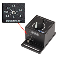
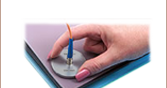
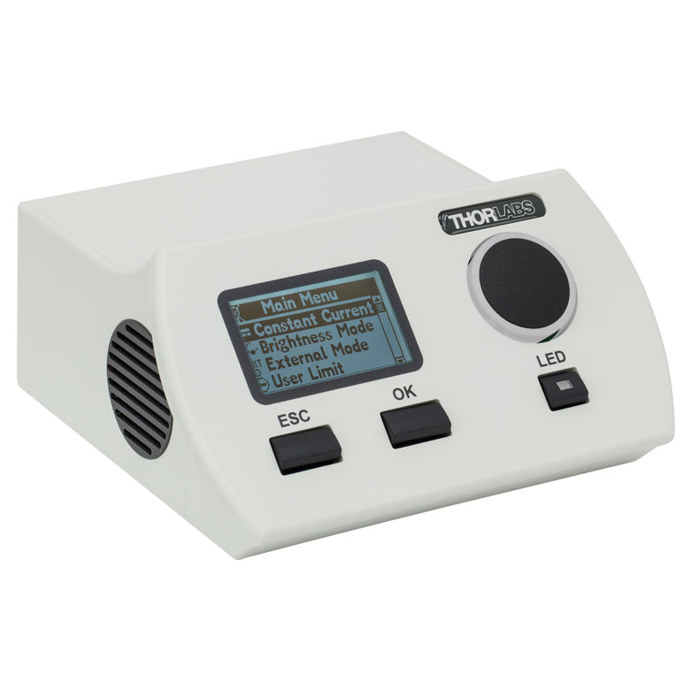
Figure 1. Adjust the LEDD1B current limit adjuster arrow with a flathead screwdriver to set the maximum current (1.0 A or less).
Setup
LED and Driver
All Optogenetics Starter Kits include a Mounted or Fiber-Coupled LED and
The LED can be operated by connecting it to the “LED” jack in the back of the LED driver. Plug the power supply (Item # KPS201) into the LED driver, and then the power supply to the main line voltage. The LED can only be driven up to a maximum current of 1.0 A without permanent damage; use a flathead screwdriver to turn the directional arrow recessed in the current limit adjuster on the front of the driver to set the maximum driving current (see image to the right). The LED driver can then be powered on by turning the knob on top of the driver clockwise.
Patch Cable and Cannula
Insert the patch cable’s SMA connector into the LED unit by threading the connector’s rotating barrel onto the LED unit’s housing. Then, depending upon your choice of interconnect or mating sleeve, the connection methodology varies.
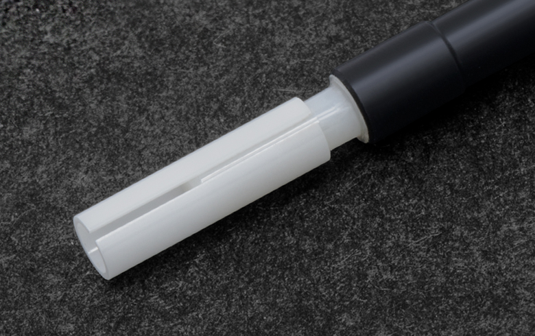
If you are using an ADAL1 (Ø1.25 mm ferrules) or ADAF1 (Ø2.5 mm ferrules) mating sleeve, place the mating sleeve onto the ferrule end of the patch cable. Leave approximately one-third of the mating sleeve length exposed for the cannula connection (Figure 2). Then, connect the mating sleeve to the cannula. To disconnect the cannula, grip the patch cable by the ferrule and mating sleeve and use a twisting motion. It is very important that the ends of the patch cable’s ferrule and the cannula’s ferrule are in physical contact (Figure 3). If they are not, the output power at the cannula tip will decrease significantly (Figure 4).
Click to Enlarge
Figure 2. The ADAF1 Mating Sleeve should be inserted 1/2 to 2/3 of the way onto the patch cable before cannula connection.

Click to Enlarge
Figure 3. Properly connected cannula and patch cable, with the cannula and patch cable in physical contact.

Click to Enlarge
Figure 4. Improperly connected cannula and patch cable, showing an air gap and light leakage.
Quick-Release Interconnect Usage
The ADAF2 (Ø2.5 mm ferrules) quick-release
Rotary Joint Patch Cables
These cables operate exactly the same way as standard patch cables, but they have an articulated joint that prevents tangling from specimen movement. SM05 (0.535"-40) mounting threads are present on the light source side of the joint. The joint can be mounted using Thorlabs’ extensive line of SM05-compatible optomechanics hardware, such as the LMR05 lens mount. Alternatively, the rotary joint can be mounted directly to the wall or ceiling of a specimen enclosure. An SM05-tapped hole can be created using Thorlabs’ 83373 SM05
Operation
Make sure the current limit on the LED driver is set to 1.0
The LED can be operated using the LED driver
Continuous Wave (CW) Mode
While operating in continuous wave mode, the driver provides a constant non-modulated LED current. The user controls the LED’s power by adjusting the control knob.
Trigger (TRIG) Mode
This mode operates using an externally applied TTL signal to pulse the LED output. The width of the TTL signal can be used to define the LED pulse width as well. The brightness of the LED is adjusted using the control knob.
Modulation (MOD) Mode
This mode allows the LED driver to be controlled completely by an external voltage. LED intensity varies with the input voltage, from off (0V) to maximum brightness (5V).
Fiber Care
Patch cable connectors should be cleaned every time the cable is mated, tested, or reconfigured. Clean the fiber
Further Reading
- http://www.stanford.edu/group/dlab/optogenetics/
- http://www.openoptogenetics.org/index.php?title=Main_Page
- Aravanis A, Wang LP, Zhang F, Meltzer L,
Mogri M, Schneider MB, Deisseroth K. An optical neural interface: in vivo control of rodent motor cortex with integrated fiberoptic and optogenetic technology. J. Neural Eng. 2007 Sept; 4:S143-S156. - Gradinaru V, Thompson KR, Zhang F,
Mogri M, Kay K, Schneider MB, Deisseroth K. Targeting and readout strategies for fast optical neural control in vitro and in vivo. J Neurosci. 2007 Dec 26;27(52):14231-8. - Zhang F, Gradinaru V, Adamantidis AR, Durand R, Airan RD, de Lecea L, Deisseroth K. Optogenetic interrogation of neural circuits: technology for probing mammalian brain structures. Nat Protoc. 2010;5(3):439-56. Epub 2010 Feb 18.
- Yizhar O, Fenno LE, Davidson TJ, Mogri M, Deisseroth K. Optogenetics in Neural Systems. Neuron. 2011 July;72:9-34.

Click to Enlarge
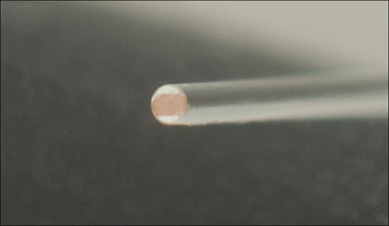
Figure 3. Cleaved Fiber After Pulling
Fiber Cleaving
Uncleaved cannula must be cleaved, or precision cut, before use. A high-quality fiber cleave will preserve the fidelity of the optical signal transmitted through the tip of the fiber. We recommend the following procedure for cleaving the fiber end.
Required Materials
- Uncleaved Fiber Optic Cannula*
- Marker
- S90R Fiber Scribe*
- BFG1 Bare Fiber Gripper*
- KW32 Kimwipes®† Lint-Free Wipes
- Isopropyl Alcohol or FCS3 Fiber Cleaning Fluid*
- JEL10 Eye Loupe* or Microscope
- FTDU Fiber Optic Disposal Unit*
- Safety Goggles/Glasses
Starred (*) items are provided in kits with uncleaved cannulae.
Cleaving Procedure
- Clean the fiber end of the cannula using a lint-free wipe and isopropyl alcohol or FCS3 fiber cleaning fluid. Do not use acetone, as this will damage the TECS cladding on the exposed fiber.
- Measure the desired length of fiber from the end of the ferrule. Mark this length on the fiber with a marker.
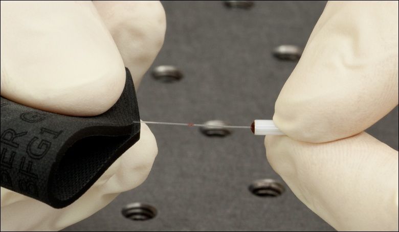
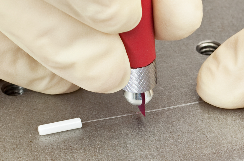
- Place the cannula on a hard surface and secure the fiber end with a finger or tape, as shown in Figure 1.
- Hold the cleaving tool perpendicular to the fiber and gently score the fiber as shown in Figure 1 to the right. Do not apply excessive pressure. The fiber should not break off at this point. This step is critical in obtaining a good cleave. If the scribe is made too hard, the fiber will break instead of
cleaving . If the scribe is too light, the fiber will notcleave . - Hold the cannula in one hand, and grip the fiber end with a bare fiber gripper in the other end as shown in Figure 2. Pull the fiber straight back until the fiber cleaves as shown in Figure 3. Dispose of the scrap fiber end in the FTDU or any medical or fiber sharps container.
- If the fiber does not break with a moderate amount of tension, repeat steps 4-5 above applying slightly more pressure when scoring. Inspect the cleave using an eye loupe or microscope.
A good cleave will be flat across the fiber and perpendicular to the optic axis. There should be no ‘tag’ (i.e., protrusion) from the edge of the fiber. The region where the initial scribe was made may be visible. It should be less than 5% of the core diameter. Be patient as this process takes a little practice. Please be aware that it will be more difficult to achieve a high-quality cleave in large-core-diameter fibers compared to thinner fibers. A view of a properly cleaved fiber end as seen through a Thorlabs' JEL10 eye loupe is shown in Figure 4.
Click Here for a Print Friendly Version of this Procedure
Thorlabs also offers a full fiber termination manual, which covers fiber termination and bare fiber cleaving. It can be downloaded for free here, or a paper copy can be purchased here.
†Kimwipes® is a registered trademark of the Kimberly-Clark Corporation.
| Posted Comments: | |
user
(posted 2013-04-08 19:24:12.54) What ever happened to your rotary joint. I think there used to be a page or at least an image of a finished unit. I really need one for my research tcohen
(posted 2013-04-09 11:04:00.0) Response from Tim at Thorlabs: Thank you for your interest. The rotary joint went through a redesign so that we could provide the best quality before initial release. We have plans to release four different units within the next couple of weeks and we will be adding supporting documentation to the website upon release. If you would like to discuss the specs, timeline or fit within your application, please contact us at techsupport@thorlabs.com. user
(posted 2013-04-05 21:45:22.623) when will a kit with rotary joint be available? |
| Quick Links | |||
|---|---|---|---|
| Single-Site Stimulation | |||
| One Light Source to One Cannula Implant | |||
| Multilateral Stimulation | |||
| One Light Source to Two Cannula Implants Using Rotary Joint Splitter | |||
| One or Two Light Sources to Two Cannula Implants | |||
| One Light Source to Seven Cannula Implants | |||
| Two Light Sources into One Dual-Core Cannula Implant | |||
| Illumination | |||
| Fiber-Coupled LEDs and Drivers | |||
Optogenetics Selection Guide
Thorlabs offers a wide range of optogenetics components; the compatibility of these products in select standard configurations is discussed in detail here. Please contact Technical Support for assistance with items outside the scope of this guide, including custom fiber components for optogenetics.
Single-Site Stimulation
One Light Source to One Cannula Implant
The most straightforward method for in vivo light stimulation of a specimen is to use a single fiber optic with a single LED light source. The single wavelength LED is powered by an LED driver, and then the illumination output is fiber-coupled into a patch cable, which connects to the implanted cannula. See the graphics and expandable compatibility tables below for the necessary patch cables and cannulae to create this setup. To choose the appropriate LED and driver, see below or the full web presentation.
Click on Each Component for More Information

Click to See Ø1.25 mm (LC) Ferrule Compatible Patch Cables, Cannulae, and Interconnects
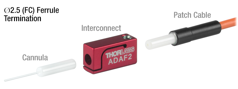
Click to See Ø2.5 mm (FC) Ferrule Compatible Patch Cables, Cannulae, and Interconnects
Multilateral Stimulation
The ability to accurately and simultaneously direct light to multiple locations within a specimen is desired for many types of optogenetics experiments. For example, bilateral stimulation techniques typically target neurons in two spatially separated regions in order to induce a desired behavior. In more complex experiments involving the simultaneous inhibition and stimulation of neurons, delivering light of two different monochromatic wavelengths within close proximity enables the user to perform these experiments without implanting multiple cannulae, which can increase stress on the specimen.
Multilateral stimulation can be achieved with several different configurations depending on the application requirements. The sections below illustrate examples of different configurations using Thorlabs' optogenetics products.
Option 1: One Light Source to Two Cannula Implants Using Rotary Joint Splitter
Thorlabs' RJ2 1x2 Rotary Joint Splitter is designed for optogenetics applications and is used to split light from a single input evenly between two outputs. The rotary joint interface allows connected patch cables to freely rotate, reducing the risk of fiber damage caused by a moving specimen. See the graphic and compatibility table below for the necessary cables and cannulae to create this setup. For LEDs and drivers, see below or the full web presentation.
Click to See Ø1.25 mm (LC) Ferrule Components Recommended for Use with RJ2 Rotary Joint Splitter
Click to See Ø2.5 mm (FC) Ferrule Components Recommended for Use with RJ2 Rotary Joint Splitter
Option 2: One or Two Light Sources to Two Cannula Implants
If the intent is for one LED source to connect to two cannulae for simultaneous light modulation, then a bifurcated fiber bundle can be used to split the light from the LED into each respective cannula. For dual wavelength stimulation (mixing two wavelengths in a single cannula) or a more controlled split ratio between cannula, one can use a multimode coupler to connect one or two LEDs to the cannulae. If one cable end is left unused, the spare coupler cable end may be terminated by a light trap. See the graphic and compatibility table below for the necessary cables and cannulae to create this setup. For LEDs and drivers, see below or the full web presentation.
Click on Each Component Below for More Information
Option 3: One Light Sources to Seven Cannula Implants
If the intent is for one LED source to connect to seven cannulae for simultaneous light modulation, then a 1-to-7 fiber bundle can be used to split the light from the LED into each respective cannula. See the graphic and compatibility table below for the necessary cables and cannulae to create this setup. For LEDs and drivers, see below or the full web presentation.
Click on Each Component Below for More Information
Two Light Sources into One Dual-Core Cannula Implant
For bilateral stimulation applications where the two cannulas need to be placed in close proximity (within ~1 mm), Thorlabs offers dual-core patch cables and cannulae that are designed for this specific application. Each core is driven by a separate light source, enabling users to stimulate and/or supress nerve cells in the same region of the specimen. See the graphic and compatibility table below for the necessary cables and cannulae to create this setup. For LEDs and drivers, see below or the full web presentation.
Click on Each Component for More Information
| Part Selection Table (Click Links for Item Description Popup) | |||||||||
|---|---|---|---|---|---|---|---|---|---|
| Common Fiber Properties | |||||||||
| Core Diameter | 200 µm | ||||||||
| Wavelength Range | 400 - 2200 nm | ||||||||
| NA | 0.39 | ||||||||
| Fiber Type | FT200EMT | ||||||||
| Ferrule Stylea | FC (Ø2.5 mm) | ||||||||
| Dual-Core Patch Cable | FC/PC Input | BFY32FL1 | |||||||
| SMA905 Input | BFY32SL1 | ||||||||
| Compatible Mating Sleeve/Interconnect | ADAF1 ADAF2 ADAF4-5 |
||||||||
| Dual-Core Fiber Optic Cannulaec | Stainless Steel | CFM32L10 CFM32L20 |
|||||||
| LED Item # | Wavelengtha | Typical Opsin | Output Powerb | Color |
|---|---|---|---|---|
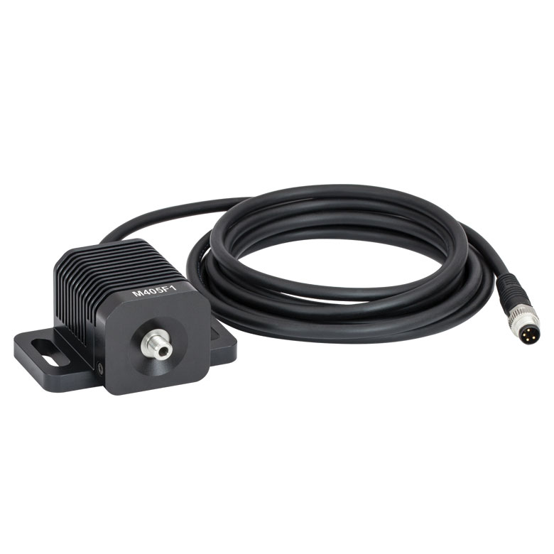
| M385F1c | 385 nm | EBFP, moxBFP | 10.7 mW | UV |
| M405F1c | 405 nm | mmilCFP, hcriGFP | 3.7 mW | UV |
| M430F1 | 430 nm | ChR2 | 7.5 mW | Violet |
| M455F3 | 455 nm | ChIEF, bPAC | 24.5 mW | Royal Blue |
| M505F3 | 505 nm | ChRGR, Opto-α1AR, Opto-β2AR | 11.7 mW | Cyan |
| M530F2 | 530 nm | C1V1, VChR1 | 9.6 mW | Green |
| M565F3 | 565 nm | Arch, VChR1-SFO | 13.5 mW | Lime |
| M595F2 | 595 nm | ChR2-SFO, eNpHR3.0 | 11.5 mW | Amber |
| M625F2 | 625 nm | ReChR | 17.5 mW | Red |
Illumination
Click to Enlarge
M405F1
Fiber-Coupled LEDs and Drivers
Our fiber-coupled LEDs are ideal light sources for optogenetics applications. They feature a variety of wavelength choices and a convenient interconnection to optogenetics patch cables. Thorlabs offers fiber-coupled LEDs with nominal wavelengths ranging from 280 nm to 1050 nm. See the table to the right for the LEDs with the most popular wavelengths for optogenetics. A table of compatible LED drivers can be viewed by clicking below.


| Item # | Product Description | Quantity | Alternate Items |
|---|---|---|---|
| Light Source | |||
| M470L5 | 470 nm Mounted LED | 1 | Alternate Fiber-Coupled LEDsa |
| SM1L05 | SM1-Threaded Lens Tube | 1 | |
| SM1SMA | SMA Fiber Adapter | 1 | |
| LEDD1B | LED Driver | 1 | Alternate LED Drivers |
| KPS201 | LED Driver Power Supply | 1 | |
| Cannulae | |||
| CFM12L02 | 2 mm Length Cannula | 5 | Alternate Cannulae |
| CFM12L05 | 5 mm Length Cannula | 5 | |
| CFM12L10 | 10 mm Length Cannula | 5 | |
| CFM12L20 | 20 mm Length Cannula | 5 | |
| CFM12U-20 | Uncleaved Cannula, 20 Pack | 1 | |
| Patch Cables and Cannula Connectors | |||
| M77L01 | Standard Patch Cable | 1 | Alternate Patch Cables |
| RJPSF2 | Rotary Joint Patch Cable | 1 | |
| ADAF2 | Interconnect | 1 | Cannula Connectors |
| ADAF1-5 | Mating Sleeves (Pack of Five)b | 1 | |
| Cleaving Supplies | |||
| S90R | Fiber Optic Scribe | 1 | Alternate Cleavers |
| FS201 | Fiber Inspection Scope | 1 | Alternate Inspection Tools |
| JEL10 | Eye Loupe | 1 | |
| BFG1 | Bare Fiber Gripper | 1 | Fiber Termination Tools |
| Tools for Cannula Implantation | |||
| XCF | Stereotaxic Cannula Holder | 1 | Alternate Cannula Holders/ Adapters |
| XC7 | Cannula Holder Adapter Arm | 1 | |
| XC-CLAMP | Cannula Holder Adapter Clamp | 1 | |
| Fiber Handling Supplies | |||
| TZ2 | Optic Tweezers | 1 | Alternate Fiber Care Supplies |
| CKF | Fiber Cleaning Kit | 1 | |
| FTDU | Fiber Disposal Unit | 1 | |
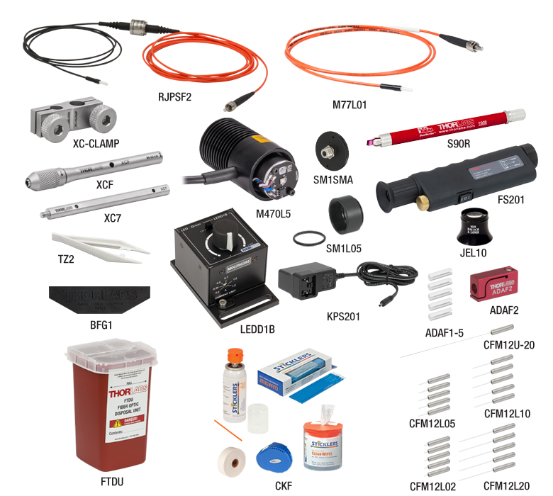
Click to Enlarge
This kit features Ø200 μm fiber optic cannulae with Ø2.5 mm ferrules. This fiber size is less invasive for implantation, while the Ø2.5 mm ferrules provide easier handling and a more robust connection to the specimen.
Multiple patch cable options provide flexibility for a range of experimental setups. The standard patch cable is sufficient for sedated specimens. For experiments with mobile specimens, the rotary joint patch cable provides free movement of the cable via an integrated rotary joint interface. This reduces the risk of damage when the specimen moves, with higher light transmission and lower variation in rotational transmission than a separate rotary joint and patch cables solution.
To purchase this kit, its components can be added all at once to the shopping cart using the "Add Kit" button at the bottom of the ordering area, or individually using the shopping cart icon next to each item. Items may be removed from the default item list by changing the value in the "Qty" box to 0 before clicking the "Add Kit" button. To further customize the kit by adding alternative items, they can be added to the shopping cart via the alternate pages above or by using the "Quick View" links on the OG Selection Guide tab. This tab provides a comprehensive list of cannulae, sleeves, patch cables, and LEDs available for optogenetics studies.
| Item # | Product Description | Quantity | Alternate Items |
|---|---|---|---|
| Light Source | |||
| M470L5 | 470 nm Mounted LED | 1 | Alternate Fiber-Coupled LEDsa |
| SM1L05 | SM1-Threaded Lens Tube | 1 | |
| SM1SMA | SMA Fiber Adapter | 1 | |
| LEDD1B | LED Driver | 1 | Alternate LED Drivers |
| KPS201 | LED Driver Power Supply | 1 | |
| Cannulae | |||
| CFML12L02 | 2 mm Length Cannula | 5 | Alternate Cannulae |
| CFML12L05 | 5 mm Length Cannula | 5 | |
| CFML12L10 | 10 mm Length Cannula | 5 | |
| CFML12L20 | 20 mm Length Cannula | 5 | |
| CFML12U-20 | Uncleaved Cannula, 20 Pack | 1 | |
| Patch Cables and Cannula Connectors | |||
| M89L01 | Standard Patch Cable | 1 | Alternate Patch Cables |
| RJPSL2 | Rotary Joint Patch Cable | 1 | |
| ADAL3 | Interconnect | 1 | Cannula Connectors |
| ADAL1-5 | Mating Sleeves (Pack of Five)b | 1 | |
| Cleaving Supplies | |||
| S90R | Fiber Optic Scribe | 1 | Alternate Cleavers |
| FS201 | Fiber Inspection Scope | 1 | Alternate Inspection Tools |
| FS200-LC | Inspection Scope Adapter | 1 | |
| JEL10 | Eye Loupe | 1 | |
| BFG1 | Bare Fiber Gripper | 1 | Fiber Termination Tools |
| Tools for Cannula Implantation | |||
| XCL | Stereotaxic Cannula Holder | 1 | Alternate Cannula Holders/ Adapters |
| XC7 | Cannula Holder Adapter Arm | 1 | |
| XC-CLAMP | Cannula Holder Adapter Clamp | 1 | |
| Fiber Handling Supplies | |||
| TZ2 | Optic Tweezers | 1 | Alternate Fiber Care Supplies |
| CKF | Fiber Cleaning Kit | 1 | |
| FTDU | Fiber Disposal Unit | 1 | |
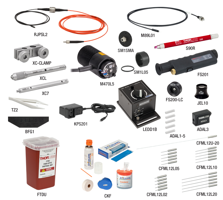
Click to Enlarge
This kit features Ø200 μm fiber optic cannulae with Ø1.25 mm ferrules, a standard patch cable, and a rotary joint patch cable. This fiber size is less invasive for implantation, while the Ø1.25 mm ferrules minimize stress on the specimen.
Multiple patch cable options provide flexibility for a range of experimental setups. The standard patch cable is sufficient for sedated specimens. For experiments with mobile specimens, the rotary joint patch cable provides free movement of the cable via an integrated rotary joint interface. This reduces the risk of damage when the specimen moves, with higher light transmission and lower variation in rotational transmission than a separate rotary joint and patch cables solution.
To purchase this kit, its components can be added all at once to the shopping cart using the "Add Kit" button at the bottom of the ordering area, or individually using the shopping cart icon next to each item. Items may be removed from the default item list by changing the value in the "Qty" box to 0 before clicking the "Add Kit" button. To further customize the kit by adding alternative items, they can be added to the shopping cart via the alternate pages above or by using the "Quick View" links on the OG Selection Guide tab. This tab provides a comprehensive list of cannulae, sleeves, patch cables, and LEDs available for optogenetics studies.
| Item # | Product Description | Quantity | Alternate Items |
|---|---|---|---|
| Light Source | |||
| M470L5 | 470 nm Mounted LED | 1 | Alternate Fiber-Coupled LEDsa |
| SM1L05 | SM1-Threaded Lens Tube | 1 | |
| SM1SMA | SMA Fiber Adapter | 1 | |
| LEDD1B | LED Driver | 1 | Alternate LED Drivers |
| KPS201 | LED Driver Power Supply | 1 | |
| Cannulae | |||
| CFM14L02 | 2 mm Length Cannula | 5 | Alternate Cannulae |
| CFM14L05 | 5 mm Length Cannula | 5 | |
| CFM14L10 | 10 mm Length Cannula | 5 | |
| CFM14L20 | 20 mm Length Cannula | 5 | |
| Patch Cables and Cannula Connectors | |||
| M79L01 | Standard Patch Cable | 1 | Alternate Patch Cables |
| RJPSF4 | Rotary Joint Patch Cable | 1 | |
| ADAF2 | Interconnect | 1 | Cannula Connectors |
| ADAF1-5 | Mating Sleeves (Pack of Five)b | 1 | |
| Tools for Cannula Implantation | |||
| XCF | Stereotaxic Cannula Holder | 1 | Alternate Cannula Holders/ Adapters |
| XC7 | Cannula Holder Adapter Arm | 1 | |
| XC-CLAMP | Cannula Holder Adapter Clamp | 1 | |
| Fiber Handling Supplies | |||
| FS201 | Fiber Inspection Scope | 1 | Alternate Inspection Tools |
| TZ2 | Optic Tweezers | 1 | Alternate Fiber Care Supplies |
| CKF | Fiber Cleaning Kit | 1 | |
| FTDU | Fiber Disposal Unit | 1 | |
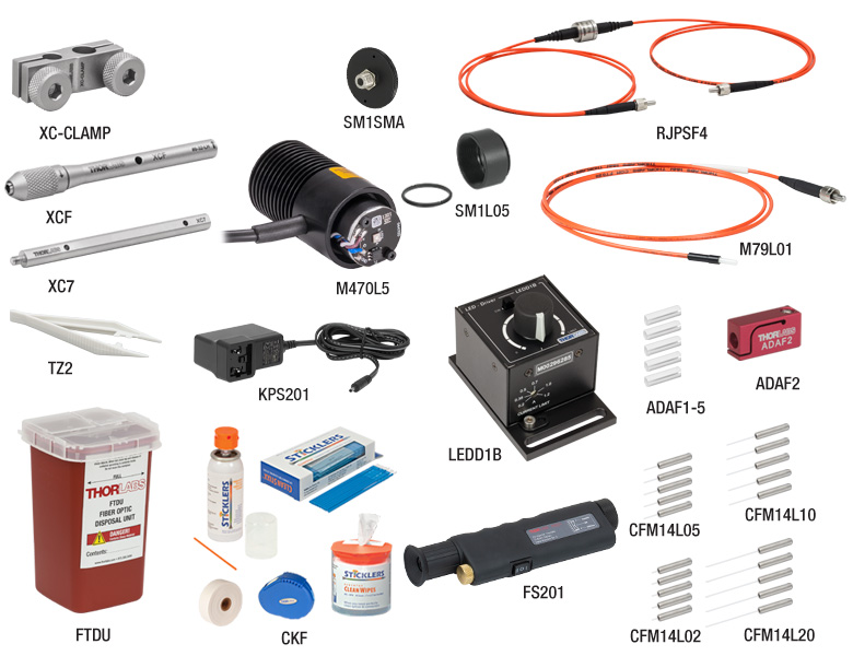
Click to Enlarge
This kit features Ø400 μm fiber optic cannulae with Ø2.5 mm ferrules and a standard patch cable. This fiber size is more durable for implantation with larger specimens, while the Ø2.5 mm ferrules provide easier handling and a more robust connection. This kit does not come with uncleaved cannulae or cleaving tools.
Multiple patch cables options provide flexibility for a range of experimental setups. The standard patch cable is sufficient for sedated specimens. For experiments with mobile specimens, the rotary joint patch cable provides free movement of the cable via an integrated rotary joint interface. This reduces the risk of damage when the specimen moves, with higher light transmission and lower variation in rotational transmission than a separate rotary joint and patch cables solution.
To purchase this kit, its components can be added all at once to the shopping cart using the "Add Kit" button at the bottom of the ordering area, or individually using the shopping cart icon next to each item. Items may be removed from the default item list by changing the value in the "Qty" box to 0 before clicking the "Add Kit" button. To further customize the kit by adding alternative items, they can be added to the shopping cart via the alternate pages above or by using the "Quick View" links on the OG Selection Guide tab. This tab provides a comprehensive list of cannulae, sleeves, patch cables, and LEDs available for optogenetics studies.
| Item # | Product Description | Quantity | Alternate Items |
|---|---|---|---|
| Light Source | |||
| M470L5 | 470 nm Mounted LED | 1 | Alternate Fiber-Coupled LEDsa |
| SM1L05 | SM1-Threaded Lens Tube | 1 | |
| SM1SMA | SMA Fiber Adapter | 1 | |
| LEDD1B | LED Driver | 1 | Alternate LED Drivers |
| KPS201 | LED Driver Power Supply | 1 | |
| Cannulae | |||
| CFML14L02 | 2 mm Length Cannula | 5 | Alternate Cannulae |
| CFML14L05 | 5 mm Length Cannula | 5 | |
| CFML14L10 | 10 mm Length Cannula | 5 | |
| CFML14L20 | 20 mm Length Cannula | 5 | |
| Patch Cables and Cannula Connectors | |||
| M98L01 | Standard Patch Cable | 1 | Alternate Patch Cables |
| RJPSL4 | Rotary Joint Patch Cable | 1 | |
| ADAL3 | Interconnect | 1 | Cannula Connectors |
| ADAL1-5 | Mating Sleeves (Pack of Five)b | 1 | |
| Tools for Cannula Implantation | |||
| XCL | Stereotaxic Cannula Holder | 1 | Alternate Cannula Holders/ Adapters |
| XC7 | Cannula Holder Adapter Arm | 1 | |
| XC-CLAMP | Cannula Holder Adapter Clamp | 1 | |
| Fiber Handling Supplies | |||
| FS201 | Fiber Inspection Scope | 1 | Alternate Inspection Tools |
| FS200-LC | Inspection Scope Adapter | 1 | |
| TZ2 | Optic Tweezers | 1 | Alternate Fiber Care Supplies |
| CKF | Fiber Cleaning Kit | 1 | |
| FTDU | Fiber Disposal Unit | 1 | |
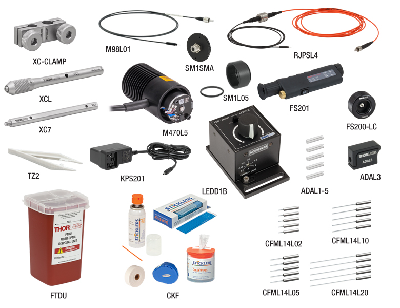
Click to Enlarge
This kit features Ø400 μm fiber optic cannulae with Ø1.25 mm ferrules and a standard patch cable. This fiber size is more durable for implantation with larger specimens, while the Ø1.25 mm ferrules minimize stress on the specimen. This kit does not come with uncleaved cannulae or cleaving tools.
Multiple patch cables options provide flexibility for a range of experimental setups. The standard patch cable is sufficient for sedated specimens. For experiments with mobile specimens, the rotary joint patch cable provides free movement of the cable via an integrated rotary joint interface. This reduces the risk of damage when the specimen moves, with higher light transmission and lower variation in rotational transmission than a separate rotary joint and patch cables solution.
To purchase this kit, its components can be added all at once to the shopping cart using the "Add Kit" button at the bottom of the ordering area, or individually using the shopping cart icon next to each item. Items may be removed from the default item list by changing the value in the "Qty" box to 0 before clicking the "Add Kit" button. To further customize the kit by adding alternative items, they can be added to the shopping cart via the alternate pages above or by using the "Quick View" links on the OG Selection Guide tab. This tab provides a comprehensive list of cannulae, sleeves, patch cables, and LEDs available for optogenetics studies.