 Products Home / Optical Elements / Optical Mirrors / Hot and Cold Mirrors / Hot and Cold Mirrors: UV Fused Silica Substrate
Hot and Cold Mirrors: UV Fused Silica Substrate
- Protect Heat-Sensitive Setups with Minimal Deformation
- Durable Dielectric Coating
- Hot Mirrors Reflect IR
- Cold Mirrors Reflect Visible Light
M254C45
M254H00


Please Wait
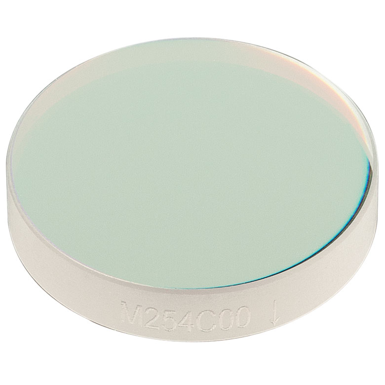
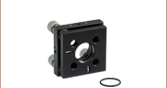
Engraved Arrow Indicates Direction of Propagation
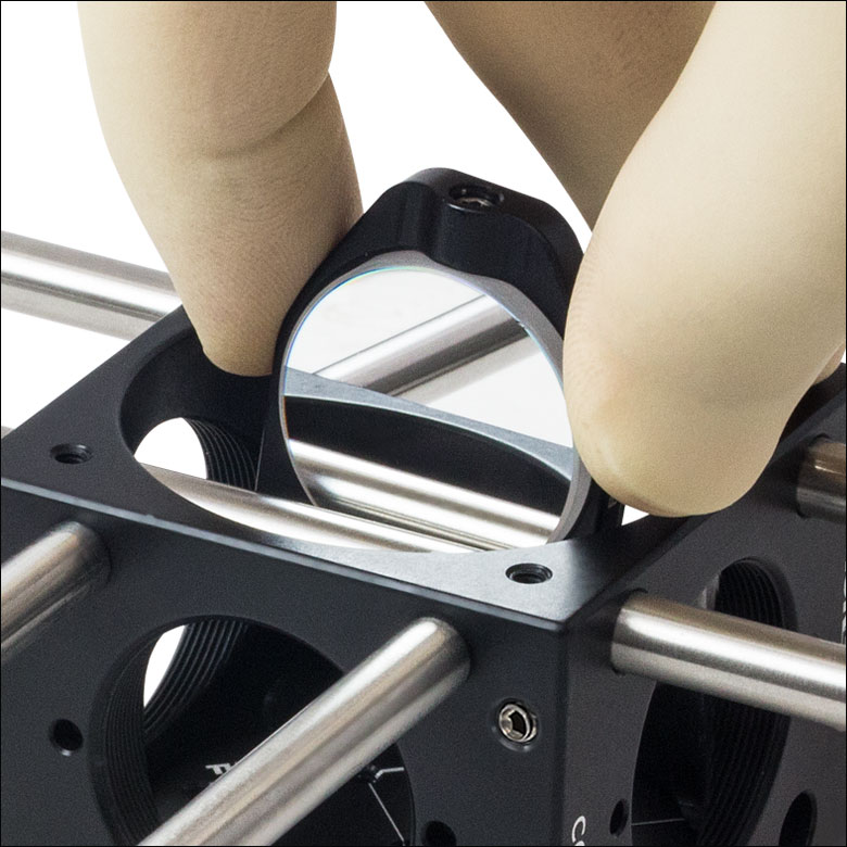
Click to Enlarge
A Cold Mirror Mounted in a B5C1 being Placed into a C6WR Cage Cube
Features
- Ø1" Unmounted Hot and Cold Mirrors
- 0° and 45° AOI Available
- UV Fused Silica Substrate Provides Low Thermal Expansion Coefficient and Longevity
- 30 arcmin Wedge Minimizes Interference Effects
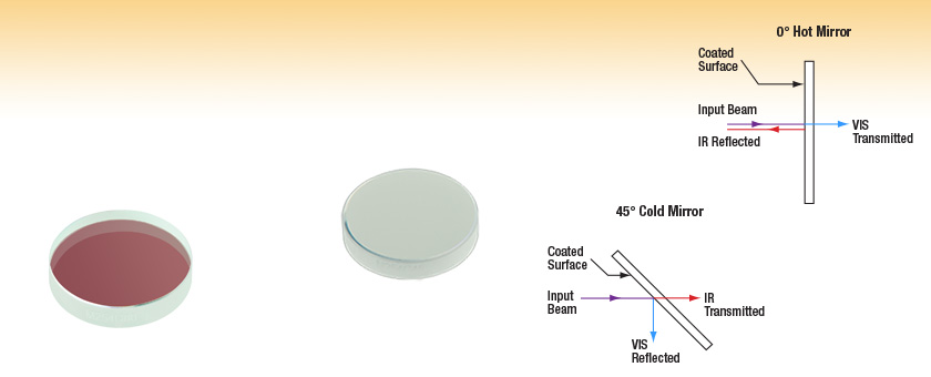
Thorlabs' UV Fused Silica Hot and Cold Mirrors are Ø1" unmounted mirrors that are ideal for use in situations where heat could severely damage an experimental setup. Hot mirrors transmit visible light and reflect IR, allowing them to protect heat-sensitive elements by reflecting IR energy. In contrast, cold mirrors reflect visible light and transmit IR. They are ideal for projection applications and for use as low- and high-pass filters.
These UV fused silica mirrors have a lower coefficient of thermal expansion than our Soda-Lime Hot and Cold Mirrors, which allows them to absorb heat without deforming. They feature a 30 arcmin wedge that minimizes interference effects, especially for the versions designed for a 45° incident angle. They are feature a durable, hard-coated dielectric coating that is more dense than those on our soda-lime hot and cold mirrors and can withstand the normal cleaning and handling necessary when using any high-quality optical component. The UVFS substrate also offers superior longevity compared to the soda-lime glass versions.
As shown in the image to the right, these mirrors have an arrow engraved on the edge that points toward the surface without the reflective filter coating. This arrow indicates the direction that light should propagate through the mirror.
We also offer Dichroic Mirrors/Beamsplitters, which provide a greater range of cutoff frequencies.
| Specifications | |
|---|---|
| Diameter | Ø1" (Ø25.4 mm) |
| Thickness | 5 mm |
| Surface Flatness | λ/10 at 632.8 nm (Hot Mirrors) |
| Surface Quality | 20-10 Scratch-Dig |
| Wedge | 30 ± 10 arcmin |
| Coatings | |
| Hot Mirrora at 0° and 45° AOI | Tavg > 92% from 400 to 690 nm Ravg > 97% from 710 to 1200 nm |
| Cold Mirror at 0° and 45° AOI | Tavg > 92% from 710 to 1200 nm Ravg > 97% from 400 to 690 nm |
| Damage Thresholds | |
| M254H00 | 5 J/cm2 (532 nm, 10 ns, 10 Hz, Ø0.337 mm) |
| M254H45 | 5 J/cm2 (532 nm, 10 ns, 10 Hz, Ø0.346 mm) |
| M254C00 | 2 J/cm2 (532 nm, 10 ns, 10 Hz, Ø0.337 mm) |
| M254C45 | 0.5 J/cm2 (532 nm, 10 ns, 10 Hz, Ø0.346 mm) |
UV Fused Silica Transmission

Hot Mirror Transmission and Reflectance
The shaded regions below denote the transmission and reflection bands of the hot mirror for which the performance is guaranteed to meet the stated specifications. Performance outside the shaded regions will vary from lot to lot and is not guaranteed.
Please note that S- and P-polarized light have the same transmission and reflection at a 0° incident angle.
Cold Mirror Transmission and Reflectance
The shaded regions below denote the transmission and reflection bands of the cold mirror for which the performance is guaranteed to meet the stated specifications. Performance outside the shaded regions will vary from lot to lot and is not guaranteed.
Please note that S- and P-polarized light have the same transmission and reflection at a 0° incident angle.
| Damage Threshold Specifications | |
|---|---|
| Item # | Damage Threshold |
| M254H00 | 5 J/cm2 (532 nm, 10 ns, 10 Hz, Ø0.337 mm) |
| M254H45 | 5 J/cm2 (532 nm, 10 ns, 10 Hz, Ø0.346 mm) |
| M254C00 | 2 J/cm2 (532 nm, 10 ns, 10 Hz, Ø0.337 mm) |
| M254C45 | 0.5 J/cm2 (532 nm, 10 ns, 10 Hz, Ø0.346 mm) |
Damage Threshold Data for Thorlabs' Hot and Cold Mirrors
The specifications to the right are measured data for Thorlabs' hot and cold mirrors.
Laser Induced Damage Threshold Tutorial
The following is a general overview of how laser induced damage thresholds are measured and how the values may be utilized in determining the appropriateness of an optic for a given application. When choosing optics, it is important to understand the Laser Induced Damage Threshold (LIDT) of the optics being used. The LIDT for an optic greatly depends on the type of laser you are using. Continuous wave (CW) lasers typically cause damage from thermal effects (absorption either in the coating or in the substrate). Pulsed lasers, on the other hand, often strip electrons from the lattice structure of an optic before causing thermal damage. Note that the guideline presented here assumes room temperature operation and optics in new condition (i.e., within scratch-dig spec, surface free of contamination, etc.). Because dust or other particles on the surface of an optic can cause damage at lower thresholds, we recommend keeping surfaces clean and free of debris. For more information on cleaning optics, please see our Optics Cleaning tutorial.
Testing Method
Thorlabs' LIDT testing is done in compliance with ISO/DIS 11254 and ISO 21254 specifications.
First, a low-power/energy beam is directed to the optic under test. The optic is exposed in 10 locations to this laser beam for 30 seconds (CW) or for a number of pulses (pulse repetition frequency specified). After exposure, the optic is examined by a microscope (~100X magnification) for any visible damage. The number of locations that are damaged at a particular power/energy level is recorded. Next, the power/energy is either increased or decreased and the optic is exposed at 10 new locations. This process is repeated until damage is observed. The damage threshold is then assigned to be the highest power/energy that the optic can withstand without causing damage. A histogram such as that below represents the testing of one BB1-E02 mirror.

The photograph above is a protected aluminum-coated mirror after LIDT testing. In this particular test, it handled 0.43 J/cm2 (1064 nm, 10 ns pulse, 10 Hz, Ø1.000 mm) before damage.

| Example Test Data | |||
|---|---|---|---|
| Fluence | # of Tested Locations | Locations with Damage | Locations Without Damage |
| 1.50 J/cm2 | 10 | 0 | 10 |
| 1.75 J/cm2 | 10 | 0 | 10 |
| 2.00 J/cm2 | 10 | 0 | 10 |
| 2.25 J/cm2 | 10 | 1 | 9 |
| 3.00 J/cm2 | 10 | 1 | 9 |
| 5.00 J/cm2 | 10 | 9 | 1 |
According to the test, the damage threshold of the mirror was 2.00 J/cm2 (532 nm, 10 ns pulse, 10 Hz, Ø0.803 mm). Please keep in mind that these tests are performed on clean optics, as dirt and contamination can significantly lower the damage threshold of a component. While the test results are only representative of one coating run, Thorlabs specifies damage threshold values that account for coating variances.
Continuous Wave and Long-Pulse Lasers
When an optic is damaged by a continuous wave (CW) laser, it is usually due to the melting of the surface as a result of absorbing the laser's energy or damage to the optical coating (antireflection) [1]. Pulsed lasers with pulse lengths longer than 1 µs can be treated as CW lasers for LIDT discussions.
When pulse lengths are between 1 ns and 1 µs, laser-induced damage can occur either because of absorption or a dielectric breakdown (therefore, a user must check both CW and pulsed LIDT). Absorption is either due to an intrinsic property of the optic or due to surface irregularities; thus LIDT values are only valid for optics meeting or exceeding the surface quality specifications given by a manufacturer. While many optics can handle high power CW lasers, cemented (e.g., achromatic doublets) or highly absorptive (e.g., ND filters) optics tend to have lower CW damage thresholds. These lower thresholds are due to absorption or scattering in the cement or metal coating.

LIDT in linear power density vs. pulse length and spot size. For long pulses to CW, linear power density becomes a constant with spot size. This graph was obtained from [1].

Pulsed lasers with high pulse repetition frequencies (PRF) may behave similarly to CW beams. Unfortunately, this is highly dependent on factors such as absorption and thermal diffusivity, so there is no reliable method for determining when a high PRF laser will damage an optic due to thermal effects. For beams with a high PRF both the average and peak powers must be compared to the equivalent CW power. Additionally, for highly transparent materials, there is little to no drop in the LIDT with increasing PRF.
In order to use the specified CW damage threshold of an optic, it is necessary to know the following:
- Wavelength of your laser
- Beam diameter of your beam (1/e2)
- Approximate intensity profile of your beam (e.g., Gaussian)
- Linear power density of your beam (total power divided by 1/e2 beam diameter)
Thorlabs expresses LIDT for CW lasers as a linear power density measured in W/cm. In this regime, the LIDT given as a linear power density can be applied to any beam diameter; one does not need to compute an adjusted LIDT to adjust for changes in spot size, as demonstrated by the graph to the right. Average linear power density can be calculated using the equation below.

The calculation above assumes a uniform beam intensity profile. You must now consider hotspots in the beam or other non-uniform intensity profiles and roughly calculate a maximum power density. For reference, a Gaussian beam typically has a maximum power density that is twice that of the uniform beam (see lower right).
Now compare the maximum power density to that which is specified as the LIDT for the optic. If the optic was tested at a wavelength other than your operating wavelength, the damage threshold must be scaled appropriately. A good rule of thumb is that the damage threshold has a linear relationship with wavelength such that as you move to shorter wavelengths, the damage threshold decreases (i.e., a LIDT of 10 W/cm at 1310 nm scales to 5 W/cm at 655 nm):

While this rule of thumb provides a general trend, it is not a quantitative analysis of LIDT vs wavelength. In CW applications, for instance, damage scales more strongly with absorption in the coating and substrate, which does not necessarily scale well with wavelength. While the above procedure provides a good rule of thumb for LIDT values, please contact Tech Support if your wavelength is different from the specified LIDT wavelength. If your power density is less than the adjusted LIDT of the optic, then the optic should work for your application.
Please note that we have a buffer built in between the specified damage thresholds online and the tests which we have done, which accommodates variation between batches. Upon request, we can provide individual test information and a testing certificate. The damage analysis will be carried out on a similar optic (customer's optic will not be damaged). Testing may result in additional costs or lead times. Contact Tech Support for more information.
Pulsed Lasers
As previously stated, pulsed lasers typically induce a different type of damage to the optic than CW lasers. Pulsed lasers often do not heat the optic enough to damage it; instead, pulsed lasers produce strong electric fields capable of inducing dielectric breakdown in the material. Unfortunately, it can be very difficult to compare the LIDT specification of an optic to your laser. There are multiple regimes in which a pulsed laser can damage an optic and this is based on the laser's pulse length. The highlighted columns in the table below outline the relevant pulse lengths for our specified LIDT values.
Pulses shorter than 10-9 s cannot be compared to our specified LIDT values with much reliability. In this ultra-short-pulse regime various mechanics, such as multiphoton-avalanche ionization, take over as the predominate damage mechanism [2]. In contrast, pulses between 10-7 s and 10-4 s may cause damage to an optic either because of dielectric breakdown or thermal effects. This means that both CW and pulsed damage thresholds must be compared to the laser beam to determine whether the optic is suitable for your application.
| Pulse Duration | t < 10-9 s | 10-9 < t < 10-7 s | 10-7 < t < 10-4 s | t > 10-4 s |
|---|---|---|---|---|
| Damage Mechanism | Avalanche Ionization | Dielectric Breakdown | Dielectric Breakdown or Thermal | Thermal |
| Relevant Damage Specification | No Comparison (See Above) | Pulsed | Pulsed and CW | CW |
When comparing an LIDT specified for a pulsed laser to your laser, it is essential to know the following:

LIDT in energy density vs. pulse length and spot size. For short pulses, energy density becomes a constant with spot size. This graph was obtained from [1].
- Wavelength of your laser
- Energy density of your beam (total energy divided by 1/e2 area)
- Pulse length of your laser
- Pulse repetition frequency (prf) of your laser
- Beam diameter of your laser (1/e2 )
- Approximate intensity profile of your beam (e.g., Gaussian)
The energy density of your beam should be calculated in terms of J/cm2. The graph to the right shows why expressing the LIDT as an energy density provides the best metric for short pulse sources. In this regime, the LIDT given as an energy density can be applied to any beam diameter; one does not need to compute an adjusted LIDT to adjust for changes in spot size. This calculation assumes a uniform beam intensity profile. You must now adjust this energy density to account for hotspots or other nonuniform intensity profiles and roughly calculate a maximum energy density. For reference a Gaussian beam typically has a maximum energy density that is twice that of the 1/e2 beam.
Now compare the maximum energy density to that which is specified as the LIDT for the optic. If the optic was tested at a wavelength other than your operating wavelength, the damage threshold must be scaled appropriately [3]. A good rule of thumb is that the damage threshold has an inverse square root relationship with wavelength such that as you move to shorter wavelengths, the damage threshold decreases (i.e., a LIDT of 1 J/cm2 at 1064 nm scales to 0.7 J/cm2 at 532 nm):

You now have a wavelength-adjusted energy density, which you will use in the following step.
Beam diameter is also important to know when comparing damage thresholds. While the LIDT, when expressed in units of J/cm², scales independently of spot size; large beam sizes are more likely to illuminate a larger number of defects which can lead to greater variances in the LIDT [4]. For data presented here, a <1 mm beam size was used to measure the LIDT. For beams sizes greater than 5 mm, the LIDT (J/cm2) will not scale independently of beam diameter due to the larger size beam exposing more defects.
The pulse length must now be compensated for. The longer the pulse duration, the more energy the optic can handle. For pulse widths between 1 - 100 ns, an approximation is as follows:

Use this formula to calculate the Adjusted LIDT for an optic based on your pulse length. If your maximum energy density is less than this adjusted LIDT maximum energy density, then the optic should be suitable for your application. Keep in mind that this calculation is only used for pulses between 10-9 s and 10-7 s. For pulses between 10-7 s and 10-4 s, the CW LIDT must also be checked before deeming the optic appropriate for your application.
Please note that we have a buffer built in between the specified damage thresholds online and the tests which we have done, which accommodates variation between batches. Upon request, we can provide individual test information and a testing certificate. Contact Tech Support for more information.
[1] R. M. Wood, Optics and Laser Tech. 29, 517 (1998).
[2] Roger M. Wood, Laser-Induced Damage of Optical Materials (Institute of Physics Publishing, Philadelphia, PA, 2003).
[3] C. W. Carr et al., Phys. Rev. Lett. 91, 127402 (2003).
[4] N. Bloembergen, Appl. Opt. 12, 661 (1973).

In order to illustrate the process of determining whether a given laser system will damage an optic, a number of example calculations of laser induced damage threshold are given below. For assistance with performing similar calculations, we provide a spreadsheet calculator that can be downloaded by clicking the button to the right. To use the calculator, enter the specified LIDT value of the optic under consideration and the relevant parameters of your laser system in the green boxes. The spreadsheet will then calculate a linear power density for CW and pulsed systems, as well as an energy density value for pulsed systems. These values are used to calculate adjusted, scaled LIDT values for the optics based on accepted scaling laws. This calculator assumes a Gaussian beam profile, so a correction factor must be introduced for other beam shapes (uniform, etc.). The LIDT scaling laws are determined from empirical relationships; their accuracy is not guaranteed. Remember that absorption by optics or coatings can significantly reduce LIDT in some spectral regions. These LIDT values are not valid for ultrashort pulses less than one nanosecond in duration.
A Gaussian beam profile has about twice the maximum intensity of a uniform beam profile.
CW Laser Example
Suppose that a CW laser system at 1319 nm produces a 0.5 W Gaussian beam that has a 1/e2 diameter of 10 mm. A naive calculation of the average linear power density of this beam would yield a value of 0.5 W/cm, given by the total power divided by the beam diameter:
However, the maximum power density of a Gaussian beam is about twice the maximum power density of a uniform beam, as shown in the graph to the right. Therefore, a more accurate determination of the maximum linear power density of the system is 1 W/cm.
An AC127-030-C achromatic doublet lens has a specified CW LIDT of 350 W/cm, as tested at 1550 nm. CW damage threshold values typically scale directly with the wavelength of the laser source, so this yields an adjusted LIDT value:
The adjusted LIDT value of 350 W/cm x (1319 nm / 1550 nm) = 298 W/cm is significantly higher than the calculated maximum linear power density of the laser system, so it would be safe to use this doublet lens for this application.
Pulsed Nanosecond Laser Example: Scaling for Different Pulse Durations
Suppose that a pulsed Nd:YAG laser system is frequency tripled to produce a 10 Hz output, consisting of 2 ns output pulses at 355 nm, each with 1 J of energy, in a Gaussian beam with a 1.9 cm beam diameter (1/e2). The average energy density of each pulse is found by dividing the pulse energy by the beam area:

As described above, the maximum energy density of a Gaussian beam is about twice the average energy density. So, the maximum energy density of this beam is ~0.7 J/cm2.
The energy density of the beam can be compared to the LIDT values of 1 J/cm2 and 3.5 J/cm2 for a BB1-E01 broadband dielectric mirror and an NB1-K08 Nd:YAG laser line mirror, respectively. Both of these LIDT values, while measured at 355 nm, were determined with a 10 ns pulsed laser at 10 Hz. Therefore, an adjustment must be applied for the shorter pulse duration of the system under consideration. As described on the previous tab, LIDT values in the nanosecond pulse regime scale with the square root of the laser pulse duration:
This adjustment factor results in LIDT values of 0.45 J/cm2 for the BB1-E01 broadband mirror and 1.6 J/cm2 for the Nd:YAG laser line mirror, which are to be compared with the 0.7 J/cm2 maximum energy density of the beam. While the broadband mirror would likely be damaged by the laser, the more specialized laser line mirror is appropriate for use with this system.
Pulsed Nanosecond Laser Example: Scaling for Different Wavelengths
Suppose that a pulsed laser system emits 10 ns pulses at 2.5 Hz, each with 100 mJ of energy at 1064 nm in a 16 mm diameter beam (1/e2) that must be attenuated with a neutral density filter. For a Gaussian output, these specifications result in a maximum energy density of 0.1 J/cm2. The damage threshold of an NDUV10A Ø25 mm, OD 1.0, reflective neutral density filter is 0.05 J/cm2 for 10 ns pulses at 355 nm, while the damage threshold of the similar NE10A absorptive filter is 10 J/cm2 for 10 ns pulses at 532 nm. As described on the previous tab, the LIDT value of an optic scales with the square root of the wavelength in the nanosecond pulse regime:
This scaling gives adjusted LIDT values of 0.08 J/cm2 for the reflective filter and 14 J/cm2 for the absorptive filter. In this case, the absorptive filter is the best choice in order to avoid optical damage.
Pulsed Microsecond Laser Example
Consider a laser system that produces 1 µs pulses, each containing 150 µJ of energy at a repetition rate of 50 kHz, resulting in a relatively high duty cycle of 5%. This system falls somewhere between the regimes of CW and pulsed laser induced damage, and could potentially damage an optic by mechanisms associated with either regime. As a result, both CW and pulsed LIDT values must be compared to the properties of the laser system to ensure safe operation.
If this relatively long-pulse laser emits a Gaussian 12.7 mm diameter beam (1/e2) at 980 nm, then the resulting output has a linear power density of 5.9 W/cm and an energy density of 1.2 x 10⁻⁴ J/cm2 per pulse. This can be compared to the LIDT values for a WPQ10E-980 polymer zero-order quarter-wave plate, which are 5 W/cm for CW radiation at 810 nm and 5 J/cm2 for a 10 ns pulse at 810 nm. As before, the CW LIDT of the optic scales linearly with the laser wavelength, resulting in an adjusted CW value of 6 W/cm at 980 nm. On the other hand, the pulsed LIDT scales with the square root of the laser wavelength and the square root of the pulse duration, resulting in an adjusted value of 55 J/cm2 for a 1 µs pulse at 980 nm. The pulsed LIDT of the optic is significantly greater than the energy density of the laser pulse, so individual pulses will not damage the wave plate. However, the large average linear power density of the laser system may cause thermal damage to the optic, much like a high-power CW beam.
| Posted Comments: | |
Tom Berg
(posted 2023-06-07 13:06:05.427) What is the dependence of the transmission and reflectance behavior of the mirror on the AOI? e.g. using this in sunlight at variable AOI? cdolbashian
(posted 2023-06-23 12:18:58.0) Thank you for reaching out to us with this inquiry. Within the "Graphs" tab on this page, we share data for 6° and 45° AOI. I have contacted you directly regarding your specific application. Sultan Alshaibani
(posted 2023-02-26 21:37:07.953) I have a question about this dichroic mirror: is it transparent to the deep UV light?
I need a mirror that works at 0 deg and transparent to the deep UV light and reflects the visible light. do you supply such mirror? jdelia
(posted 2023-03-03 09:05:00.0) Thank you for contacting Thorlabs. I have reached out to you directly to share our scan data down into the UV range for this mirror. Christian Saggau
(posted 2021-03-16 20:00:17.0) Hi,
i would like to deposit some materials from oragnic solvents. (Acetone/DMSO/Toluene) onto the mirror - could you please lket me know if the surface would be compromised.
Regards,
Christian Saggau YLohia
(posted 2021-04-01 11:01:15.0) Hello Christian, we clean these hot/cold mirrors with acetone post-production. We don't use either DMSO or toluene so, unfortunately, we cannot comment on those due to lack of test data. Yu-Chieh LIN
(posted 2021-03-08 14:57:02.947) Hi,
Could you please provide me the reflectivity data of M254C00 and M254C45 with wavelength range in 190-300 nm?
Thank you very much! YLohia
(posted 2021-03-12 04:02:18.0) Hello, we will reach out to you directly. BAI-WEI WU
(posted 2020-07-23 21:29:59.01) Dear Sir,
I bought the M254H00 hot mirror and received the merchandise yesterday.
As I used the hot mirror, I found that the sides of the surface is not parallel, it make the reflex light do not a point but two points. can you tell me what can I do? YLohia
(posted 2020-07-24 09:28:17.0) Hello, thank you for contacting Thorlabs. These mirrors are specified for a 30 arcmin wedge angle that minimizes interference effects. The two beams that are generated are intentional. BAI-WEI WU
(posted 2020-05-18 02:53:02.11) Dear Thorlabs, I am interested in purchasing one of the hot mirrors. But I am curious whether the backside of the mirror is polished or not. YLohia
(posted 2020-05-18 01:06:15.0) Hello, thank you for contacting Thorlabs. Yes, these are all backside polished. grwoods4
(posted 2017-01-01 18:39:25.343) Do you make this fused silica cold mirror in a 2" size? tfrisch
(posted 2017-01-04 08:29:20.0) Hello, thank you for contacting Thorlabs. I will reach out to you directly about current availability of larger sizes of these IBS coated mirrors. efcunn
(posted 2016-11-14 11:56:13.707) Like a previous customer (julien.lancelot, 2014-11-27), I would also be interested in seeing the mirror's response above 1300nm, especially up to 2500nm. Is this information available? Thank you. tfrisch
(posted 2016-11-16 01:24:17.0) Hello, thank you for contacting Thorlabs. On the Graphs tab, there are links to the raw data over an extended range. fabian.luecking
(posted 2016-10-11 10:42:34.14) Are these optics also available in different formats? In my case, I would be interested in a 0.5" diameter substrate. jlow
(posted 2016-10-11 09:52:41.0) Response from Jeremy at Thorlabs: Yes we can customize this to be 1/2". I will contact you directly about the quote. shane
(posted 2016-06-30 17:52:08.243) Regarding Hot Mirror M254H00, I see the plot graph for its transmittance/reflectance %'s are stated for 8° AOI.
And, I see you'd answered another that its transmittance/reflectance %'s at 0° AOI should be comparable to that.
How much farther beyond 8° AOI can you go before transmittance/reflectance %'s are severely eroded?
I'm looking for a Hot Mirror with the widest possible ranging sweep of AOI that still maintains high transmittance/reflectance %'s for the same range as covered by the M254HOO.
I'd further be interested in larger sizes of it, too, approximately 30cm diameter. A couple to test initially, then more later if it works out. foued.amrani
(posted 2016-03-10 10:19:54.303) Dear,
what are the reflectence of your cold or hot mirrors at exactly 0° incidence angle?
thenk you
best regards. besembeson
(posted 2016-03-10 04:15:42.0) Response from Bweh at Thorlabs USA: The reflectance will be comparable to that at 8 deg, since you need a small angle to be able to position a detector. You can use the same estimates for the transmission. We have these plots under the "Graphs" tab at the following link: http://www.thorlabs.com/NewGroupPage9.cfm?ObjectGroup_ID=6108 julien.lancelot
(posted 2014-11-27 11:18:12.93) Hi there, I am interested in the transimssion and reflectivity of the 45° mirrors between 3µm and 5µm. Do you know these ? myanakas
(posted 2014-12-08 04:02:15.0) Response from Mike at Thorlabs: Thank you for your feedback. We are currently working on updating the website with this data. In the meantime I have contacted you directly with data out to 6 um. user
(posted 2014-10-02 19:00:08.48) My apologies, I have found the polarization data plotted here so please disregard my previous query. Many thanks, Ross Leyman. Ross.Leyman
(posted 2014-10-02 18:56:13.283) Hi there, do you have any plots or information regarding reflectivity/transmission curves at both S- and P-polarisation of incoming beam? Many tThanks, Ross. n.bayarjargal
(posted 2014-08-27 14:18:21.493) Can you produce an square hot mirror that is mountable in Cage Cube CM1-DCH? I just need one such item.
If not, can you offer me other possibility to use the 1 inch hot mirror in 30 mm cage system?
Sincerely,
Bayarjargal cdaly
(posted 2014-08-27 02:19:14.0) Response from Chris at Thorlabs: A 1" diameter optic can be mounted in the cage system by using the C4W or C6W cage cube with a B3C platform and B5C optic mount. Tip & tilt adjustment can be added for a mirror by using a B4C kinematic platform rather than the B3C. carlos.macias
(posted 2014-03-31 14:12:45.24) What is the dispersion like (GVD and/or GDD) in transmission or reflection for the M254C45? besembeson
(posted 2014-04-08 08:18:20.0) Response from Bweh E at Thorlabs: I will send you the theoretical plot for the group delay via email. g9622513
(posted 2013-12-10 08:06:16.337) Please provide the Damage Thresholds for CW laser @532 nm. jlow
(posted 2014-01-07 04:53:35.0) Response from Jeremy at Thorlabs: We do not have the damage threshold data for this particular optic but we estimate the damage threshold to be similar to our -E02 dielectric mirror. We have tested with the -E02 mirror with the highest power 532nm CW laser we have access to and it was able to withstand 2 kW/cm (focused to a 17µm spot size) without being damaged. fd297
(posted 2013-10-14 13:06:35.81) We planned to deposite some material from organic solvents on the mirror. Could you give me some information on the mirror material (mainly the last layer exposed to air) and how it would be affected by solvents? jlow
(posted 2013-10-15 11:33:00.0) Response from Jeremy at Thorlabs: We will contact you directly to discuss about the specific solvent you are using. jjsuberviola
(posted 2013-04-02 22:54:46.023) Dear Sir/Madam:
I would like to know what is the maximum temperature of operation for Cold Mirror M254C45.
I would like also to know if this cold mirror (M254C45) can transmitted IR beam in the opposite direction was designed.
Best regards, cdaly
(posted 2013-04-04 13:09:00.0) Response from Chris at Thorlabs to jjsuberviola: Thank you for using our feedback tool. We do not really specify a max operating temperature for these, but we suspect it will be very higher, at least 150 degrees Celsius. The mirror should be transmission and reflected from both directions in the ranges specified, but we suggest your light is incident on the side which is coated to provide this split. rpsmith
(posted 2013-03-21 21:55:04.527) What is the dispersion like (GVD and/or GDD) in transmission or reflection for M254H00? jlow
(posted 2013-04-04 12:34:00.0) Response from Jeremy at Thorlabs: We will contact you directly to provide some graphs on this. jlow
(posted 2012-08-01 16:10:00.0) Response from Jeremy at Thorlabs: The hot mirror is designed to reflect IR wavelengths (710nm to 1200nm) that may otherwise heat a heat-sensitive experimental setup. We specified a reflectivity of >97% in that wavelength range. I will get in contact with you directly to discuss about your specific application in more detail. aminakbari123
(posted 2012-07-29 04:11:15.0) Hi
I have question about this hot mirorr so please help me.
if we put mirorr between burning glass and concentrated point can we have cool concentrated point ? why?
thank you. |

For more detailed plots and downloadable data, please see the Graphs tab.
| Specifications | |
|---|---|
| Diameter | Ø1" (Ø25.4 mm) |
| Thickness | 5 mm |
| Surface Flatness | λ/10 at 632.8 nm |
| Surface Quality | 20-10 Scratch-Dig |
| Wedge | 30 ± 10 arcmin |
| Transmission | Tavg > 92% from 400 to 690 nm |
| Reflection | Ravg > 97% from 710 to 1200 nm |
| Damage Thresholds | |
|---|---|
| M254H00 | 5 J/cm2 (532 nm, 10 ns, 10 Hz, Ø0.337 mm) |
| M254H45 | 5 J/cm2 (532 nm, 10 ns, 10 Hz, Ø0.346 mm) |
The back surface of the M254H00 is uncoated, while the back surface of the M254H45 is AR coated (Rabs < 2% from 400 - 800 nm) to improve transmission.
For more detailed plots and downloadable data, please see the Graphs tab.
| Specifications | |
|---|---|
| Diameter | Ø1" (Ø25.4 mm) |
| Thickness | 5 mm |
| Surface Quality | 20-10 Scratch-Dig |
| Wedge | 30 ± 10 arcmin |
| Transmission | Tavg > 92% from 710 to 1200 nm |
| Reflection | Ravg > 97% from 400 to 690 nm |
| Damage Thresholds | |
|---|---|
| M254C00 | 2 J/cm2 (532 nm, 10 ns, 10 Hz, Ø0.337 mm) |
| M254C45 | 0.5 J/cm2 (532 nm, 10 ns, 10 Hz, Ø0.346 mm) |