 Products Home
Shack-Hartmann Wavefront Sensors
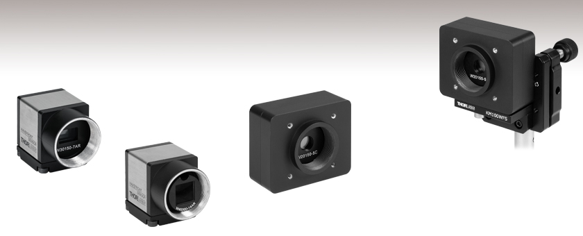
- CMOS-Based Sensors Capable of Up to 1120 fps
- Sensitivities Up to λ/200
- 300 - 1100 nm or 400 - 900 nm Wavelength Range
- Kits Available with Interchangeable Microlens Arrays (MLAs)
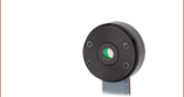
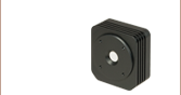
WFS20-5C
High-Speed WFS
with 150 µm Pitch MLA
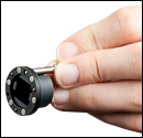
Application Idea
A WFS20-5C Mounted
on the KM100WFS
Kinematic Mount
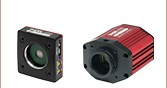
WFS31-7AR
General-Purpose WFS
with 150 µm Pitch MLA
WFS40-14AR
Large-Aperture WFS with 300 µm Pitch MLA


Please Wait
| Shack-Hartmann Wavefront Sensor Selection Guidea | |||||
|---|---|---|---|---|---|
(Sensor Head) |
Type | Max Speedb | Sensor Size | Wavefront Accuracyb |
Wavefront Sensitivityb |
| WFS31 | General Purpose | Up to 76 fps | 11.25 mm x 7.03 mm | Up to λ/60 | Up to λ/200 |
| WFS40 | Large Aperture | Up to 98 fps | Up to λ/40 | Up to λ/120 | |
| WFS20 | High Speed | ||||
(MLA)c |
Wavelength | Reflectivity | |||
| -5C | Chrome Mask | 300 - 1100 nm | 150 µm | Ø140 µm | <25% |
| -7AR | AR Coating | 400 - 900 nm | 150 µm | Ø146 µm | <1% |
| -14AR | AR Coating | 400 - 900 nm | 300 µm | <1% | |
Features
- Three Compact Sensor Head Options Include:
- General-Purpose Sensor
- Large-Aperture Sensor with 11.26 mm Square Area
- High-Speed Sensor with Frame Rates Up to 1120 fps
- High-Quality Photolithographic Microlens Array (MLA) Included
- Mounted in Exchangeable Magnetic Holder
- Individually Calibrated for the Sensor Head
- Kits Include 2 Microlens Arrays:
- 150 µm Lenslet Pitch with Chrome Mask or AR Coating
- 300 µm Lenslet Pitch with AR Coating
- Real-Time Wavefront and Intensity Distribution Measurements
- Use with CW or Pulsed Light Sources
- USB Connection for PC Operation
- Live Data Readout via TCP/IP
- Flexible Software Options
- GUI Software
- Instrument Driver Package for C Compilers
- LabWindows™/CVI
- LabVIEW®
- DataSocket for Live Data Transfer
- .Net
- Kinematic Mount Designed for Wavefront Sensors Available Separately (See Below)
|
Operating Principle
A Shack-Hartmann sensor consists of a lenslet array and a camera. When a wavefront enters the lenslet array, a spot field is created on the camera. The intensity and location of each spot is analyzed to dynamically measure the wavefronts of laser sources or characterize the wavefront distortion caused by optical components. For more details on the theory of Shack-Hartmann wavefront sensing, see the SH Tutorial tab. |
Thorlabs' Fast Shack-Hartmann Wavefront Sensors provide accurate measurements of the wavefront shape and intensity distribution of incident beams. These wavefront sensors include both a CMOS-based sensor head and a microlens array (MLA). As summarized in the table above, we offer three types of sensor heads: general purpose, large aperture, and high speed. Each type of sensor head is available with three MLA options, which have different lenslet pitches and focal lengths to provide optimal accuracy and wavefront dynamic range for the specific application.
The Item #s for these wavefront sensors have a prefix that refers to the sensor head type (WFS31, WFS40, or WFS20), and a suffix that refers to either the MLA type (-5C, -7A, or -14AR) or the kit type (
Sensor Heads
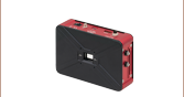
The general-purpose and large-aperture sensor heads, with Item # Prefixes WFS31 and WFS40 respectively, have a trigger input and USB 3.0 port for connection to a PC. Operation via a USB 2.0 port will result in slower performance. High-speed sensor heads, with Item # Prefix WFS20, include a control box with a trigger input and USB 2.0 port for connection to a PC. The box analyzes the camera image when the sensor is used in high-speed mode and transmits only the spot positions to the PC instead of the entire image. This lowers the volume of data sent over the USB 2.0 connection, allowing the high-speed sensors to achieve measurement speeds of >1000 fps.
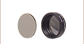
Microlens Arrays
MLAs included with our wavefront sensors have a lenslet pitch of either 150 µm or 300 µm, are either chrome masked or AR Coated, and are permanently mounted in a patented (US Patent No. 8,289,504) exchangeable magnetic holder. The magnetic holder positions the microlens array to achieve correct alignment every time it is installed on the sensor head. When a kit or an additional MLA is ordered, Thorlabs includes a removal tool, which makes it easy to switch between MLAs. To purchase an additional MLA or a different combination of MLAs for use with a sensor head, please contact Tech Support. As Thorlabs must calibrate the particular sensor head for use with each specified MLA, upgrading a sensor head for use with additional MLAs requires returning the wavefront sensor to Thorlabs.
Pickup Tool for Interchanging Microlens Arrays Included with Kits
Software
The included software package offers a user-friendly graphical interface with tools for choosing camera setting, calibration, analysis, and display options. The software also includes drivers for C compilers, LabVIEW®, LabWindows/CVI™, .Net, and DataSocket server support for integration into custom system control and data collection software. For more information on the included software or to download the latest version, see the Software tab above.
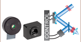
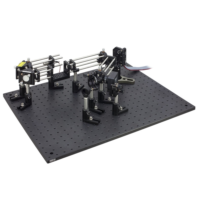
Adaptive Optics Kits
In an effort to bring adaptive optics to even more research fields, Thorlabs provides adaptive optics kits. These kits bundle the three primary components for any adaptive optics system: a deformable mirror, a Shack-Hartmann Wavefront Sensor, and real-time control software. We offer Thorlabs' Piezoelectric Deformable Mirrors as well as MEMS-based Deformable Mirrors through our partnership with Boston Micro-Machines. In addition, the kits (shown in the photo to the left) also include a light source, all collimation/imaging optics, and all necessary mounting hardware, except for a breadboard. These kits are specifically designed to provide an affordable, easy-to-use adaptive optics solution that can be integrated into a research system in hours instead of months.
| Item # Prefix | WFS31, WFS40, and WFS20 | ||||
|---|---|---|---|---|---|
| Item # Suffix | -5C(/M) | -7AR(/M) | -14AR(/M) | -K1(/M) | -K2(/M) |
| Included Microlens Array(s) | |||||
| 150 µm Lenslet Pitch, Chrome Mask, 300 - 1100 nm |
- | - | - | ||
| 150 µm Lenslet Pitch, ARa Coating, 400 - 900 nm |
- | |
- | - | |
| 300 µm Lenslet Pitch, ARa Coating, 400 - 900 nm |
- | - | |
|
|
Thorlabs' Wavefront Sensors (WFS) combine a CMOS camera and a mounted microlens array (MLA). The performance of the wavefront sensor is primarily dictated by which WFS and MLA you choose. WFS are available with one or two MLAs. New and existing WFS can also be upgraded for use with a maximum of three types of MLA by contacting Tech Support.
The Item #s for these wavefront sensors have a prefix that refers to the sensor head type (WFS31, WFS40, or WFS20), and a suffix that refers to either the MLA type (-5C, -7A, or -14AR) or the kit type (
General-Purpose WFS (Item # Prefix WFS31)
| Software Selectable Camera Resolution Optionsa | ||||||
|---|---|---|---|---|---|---|
| Camera Resolution (Pixels) | Active Area (mm) |
Microlens Spots |
Spot Count |
Frame Rate (fps)c |
||
| Normal Mode |
sub2 Modeb |
Normal Mode |
sub2 Modeb |
|||
| WFS31-5C, WFS31-7AR | ||||||
| 960 x 600 | 73 x 45 | 3285 | 13 | 23 | ||
| 1200 x 1200 | 600 x 600 | 7.03 x 7.03 | 45 x 45 | 2025 | 16 | 27 |
| 1024 x 1024 | 512 x 512 | 6.00 x 6.00 | 39 x 39 | 1521 | 21 | 32 |
| 768 x 768 | 384 x 384 | 4.50 x 4.50 | 29 x 29 | 841 | 30 | 42 |
| 512 x 512 | 256 x 256 | 3.00 x 3.00 | 19 x 19 | 361 | 52 | 59 |
| 368 x 368 | 184 x 184 | 2.16 x 2.16 | 13 x 13 | 169 | 70 | 74 |
| WFS31-14AR | ||||||
| 1920 x 1200 | 960 x 600 | 11.25 x 7.03 | 35 x 21 | 735 | 15 | 25 |
| 1200 x 1200 | 600 x 600 | 7.03 x 7.03 | 21 x 21 | 441 | 18 | 29 |
| 1024 x 1024 | 512 x 512 | 6.00 x 6.00 | 19 x 19 | 361 | 22 | 32 |
| 768 x 768 | 384 x 384 | 4.50 x 4.50 | 13 x 13 | 169 | 34 | 43 |
| 512 x 512 | 256 x 256 | 3.00 x 3.00 | 9 x 9 | 81 | 55 | 61 |
| 368 x 368 | 184 x 184 | 2.16 x 2.16 | 5 x 5 | 25 | 76 | 76 |
| Item #a | ||||
|---|---|---|---|---|
| Microlens Arrays | ||||
| Wavelength Range | ||||
| Microlens Array Aperture Size | 11.5 mm x 7.5 mm | |||
| Mask or Coating | Chrome Mask | Anti-Reflection Coating | ||
| Reflectivity | <25% | <1% | ||
| Lenslet Pitch | 150 µm | 300 µm | ||
| Lenslet Grid Type | Square Grid | |||
| Lens Shapeb | Round, Plano-Convex Spherical | Square, Plano-Convex Parabolic | ||
| Lens Size | Ø140 µm | Ø146 µm | 295 µm x 295 µm | |
| Fill Factor (Approximate)c | 68.4% | 74.4% | 96.7% | |
| Number of Active Lenslets | 73 x 45 (Max), Software-Selectable Options |
35 x 21 (Max), Software-Selectable Options |
||
| Effective Focal Length (Typical, When Mounted in WFS) |
4.1 mm | 5.2 mm | 14.6 mm | |
| Nominal Focal Length | 5.6 mm | 14.2 mm | ||
| Array Size | 12 mm x 12 mm x 1.2 mm | |||
| Substrate Material | Fused Silica (Quartz) | |||
| Camera | ||||
| Sensor Type | CMOS | |||
| Resolution | 1920 x 1200 Pixels (Max), Software-Selectable Options | |||
| Sensor Size, Max | 11.25 mm x 7.03 mm | |||
| Pixel Size | 5.86 µm x 5.86 µm | |||
| Shutter | Globald | |||
| Exposure Range | 31 µs - 2000 ms | |||
| Image Digitization | 8 Bit | |||
| Wavefront Measurement | ||||
| Accuracy (at 633 nm)e | λ/25 rms | λ/40 rms | λ/60 rms | |
| Sensitivity (at 633 nm)f | λ/80 rms | λ/120 rms | λ/200 rms | |
| Dynamic Range (at 633 nm)g | >500λ | >500λ | >250λ | |
| Local Curvatureh | >7.4 mm | >10.0 mm | >40.0 mm | |
| General Specifications | |||
|---|---|---|---|
| External Trigger Input Specifications | |||
| Trigger Slope | Software Selectable: Low-High or High-Low |
||
| Safe Static Input Voltage Range | 0 to 30 VDC | ||
| Low Level | 0.0 V to 2.0 V | ||
| High Level | 5.0 V to 24 V | ||
| Input Current (Max) | 10 mA | ||
| Pulse Width (Min) | 100 µs | ||
| Slew Rate (Min) | 35 V/ms | ||
| Housing Dimensions and Threads | |||
| Optical Input Thread | Internal C-Mount | ||
| Dimensions (H x W x D) | 35.4 mm x 29.8 mm x 47.9 mm (1.39" x 1.17" x 1.89") |
||
| External Power Supply | Max 2.8 W, via USB 3.0a | ||
| Operating Temperature | 5 to 35 °C (Non-Condensing) | ||
| Storage Temperature | -20 to 60 °C | ||
| Warm-Up Time for Rated Accuracy | 15 Minutes | ||
| Post Mountingb | One 8-32 (M4) Tap, One 1/4"-20 (M6) Tap |
||
| Cage Mounting | - | ||
| Included Thread Adapter | SM1A9: External C-Mount to Internal SM1 (1.035"-40) |
||
All technical data are valid at 23 ± 5° C and 45 ± 15% relative humidity (non-condensing).
Large-Aperture WFS (Item # Prefix WFS40)
| Software Selectable Camera Resolution Optionsa | ||||||
|---|---|---|---|---|---|---|
| Camera Resolution (Pixels) | Active Area (mm) |
Microlens Spots |
Spot Count |
Frame Rate (fps)c |
||
| Normal Mode |
sub2 Modeb | Normal Mode |
sub2 Modeb | |||
| WFS40-5C, WFS40-7AR | ||||||
| 73 x 73 | 5329 | 8 | 19 | |||
| 1536 x 1536 | 768 x 768 | 8.45 x 8.45 | 55 x 55 | 3025 | 13 | 30 |
| 1024 x 1024 | 512 x 512 | 5.63 x 5.63 | 35 x 35 | 1225 | 26 | 55 |
| 768 x 768 | 384 x 384 | 4.22 x 4.22 | 27 x 27 | 729 | 41 | 82 |
| 512 x 512 | 256 x 256 | 2.82 x 2.82 | 17 x 17 | 289 | 70 | 98 |
| 360 x 360 | 180 x 180 | 1.98 x 1.98 | 11 x 11 | 121 | 98 | 98 |
| WFS40-14AR | ||||||
| 2048 x 2048 | 1024 x 1024 | 11.26 x 11.26 | 35 x 35 | 1225 | 10 | 28 |
| 1536 x 1536 | 768 x 768 | 8.45 x 8.45 | 27 x 27 | 729 | 15 | 41 |
| 1024 x 1024 | 512 x 512 | 5.63 x 5.63 | 17 x 17 | 289 | 29 | 70 |
| 768 x 768 | 384 x 384 | 4.22 x 4.22 | 13 x 13 | 169 | 44 | 95 |
| 512 x 512 | 256 x 256 | 2.82 x 2.82 | 7 x 7 | 49 | 76 | 98 |
| 360 x 360 | 180 x 180 | 1.98 x 1.98 | 5 x 5 | 25 | 98 | 98 |
| Item #a | ||||
|---|---|---|---|---|
| Microlens Arrays | ||||
| Wavelength Range | ||||
| Microlens Array Aperture Size | 11.5 mm x 11.5 mm | |||
| Mask or Coating | Chrome Mask | Anti-Reflection Coating | ||
| Reflectivity | <25% | <1% | ||
| Lenslet Pitch | 150 µm | 300 µm | ||
| Lenslet Grid Type | Square Grid | |||
| Lens Shapeb | Round, Plano-Convex Spherical | Square, Plano-Convex Parabolic | ||
| Lens Size | Ø140 µm | Ø146 µm | 295 µm x 295 µm | |
| Fill Factor (Approximate)c | 68.4% | 74.4% | 96.7% | |
| Number of Active Lenslets | 73 x 73 (Max), Software-Selectable Options |
35 x 35 (Max), Software-Selectable Options |
||
| Effective Focal Length (Typical, When Mounted in WFS) |
4.1 mm | 5.2 mm | 14.6 mm | |
| Nominal Focal Length | 5.6 mm | 14.2 mm | ||
| Array Size | 12 mm x 12 mm x 1.2 mm | |||
| Substrate Material | Fused Silica (Quartz) | |||
| Camera | ||||
| Sensor Type | CMOS | |||
| Resolution | 2048 x 2048 Pixels (Max), Software-Selectable Options | |||
| Sensor Size, Max | 11.26 mm x 11.26 mm | |||
| Pixel Size | 5.5 µm x 5.5 µm | |||
| Shutter | Globald | |||
| Exposure Range | 77 µs - 499 ms | |||
| Image Digitization | 8 Bit | |||
| Wavefront Measurement | ||||
| Accuracy (at 633 nm)e | λ/25 rms | λ/30 rms | λ/40 rms | |
| Sensitivity (at 633 nm)f | λ/80 rms | λ/100 rms | λ/120 rms | |
| Dynamic Range (at 633 nm)g | >500λ | >500λ | >250λ | |
| Local Curvatureh | >7.4 mm | >10.0 mm | >40.0 mm | |
| General Specifications | |||
|---|---|---|---|
| External Trigger Input Specifications | |||
| Trigger Slope | Software Selectable: Low-High or High-Low |
||
| Safe Static Input Voltage Range | 0 to 30 VDC | ||
| Low Level | 0.0 V to 2.0 V | ||
| High Level | 5.0 V to 24 V | ||
| Input Current (Max) | 10 mA | ||
| Pulse Width (Min) | 100 µs | ||
| Slew Rate (Min) | 35 V/ms | ||
| Housing Dimensions and Threads | |||
| Optical Input Thread | Internal C-Mount | ||
| Dimensions (H x W x D) | 35.4 mm x 29.8 mm x 48.3 mm (1.39" x 1.17" x 1.90") |
||
| External Power Supply | Max 2.9 W, via USB 3.0a | ||
| Operating Temperature | 5 to 35 °C (Non-Condensing) | ||
| Storage Temperature | -20 to 60 °C | ||
| Warm-Up Time for Rated Accuracy | 15 Minutes | ||
| Post Mountingb | One 8-32 (M4) Tap, One 1/4"-20 (M6) Tap |
||
| Cage Mounting | - | ||
| Included Thread Adapter | SM1A9: External C-Mount to Internal SM1 (1.035"-40) |
||
All technical data are valid at 23 ± 5° C and 45 ± 15% relative humidity (non-condensing).
High-Speed WFS (Item # Prefix WFS20)
| Software Selectable Camera Resolution Optionsa | ||||||
|---|---|---|---|---|---|---|
| Camera Resolution (Pixels) |
Active Area (mm) |
Microlens Spots |
Spot Count |
Frame Rate (fps)b | ||
| Normal Mode |
2X Binningc |
Mode |
||||
| WFS20-5C and WFS20-7AR | ||||||
| 1645 | 23 | 58 | 150 | |||
| 1080 x 1080 | 5.40 x 5.40 | 35 x 35 | 1225 | 29 | 69 | 166 |
| 768 x 768 | 3.84 x 3.84 | 23 x 23 | 529 | 50 | 144 | 350 |
| 512 x 512 | 2.56 x 2.56 | 15 x 15 | 225 | 79 | 320 | 710 |
| 360 x 360 | 1.80 x 1.80 | 11 x 11 | 121 | 116 | 630 | 880 |
| WFS20-14AR | ||||||
| 1440 x 1080 | 7.20 x 5.40 | 23 x 17 | 391 | 28 | 92 | 183 |
| 1080 x 1080 | 5.40 x 5.40 | 17 x 17 | 289 | 33 | 123 | 226 |
| 768 x 768 | 3.84 x 3.84 | 11 x 11 | 121 | 50 | 258 | 394 |
| 512 x 512 | 2.56 x 2.56 | 7 x 7 | 49 | 79 | 450 | 725 |
| 360 x 360 | 1.80 x 1.80 | 5 x 5 | 25 | 116 | 648 | 1120 |
| Item #a | ||||
|---|---|---|---|---|
| Microlens Arrays | ||||
| Wavelength Range | ||||
| Microlens Array Aperture Size | Ø9 mm | |||
| Mask or Coating | Chrome Mask | Anti-Reflection Coating | ||
| Reflectivity | <25% | <1% | ||
| Lenslet Pitch | 150 µm | 300 µm | ||
| Lenslet Grid Type | Square Grid | |||
| Lens Shapeb | Round, Plano-Convex Spherical | Square, Plano-Convex Parabolic | ||
| Lens Size | Ø140 µm | Ø146 µm | 295 µm x 295 µm | |
| Fill Factor (Approximate)c | 68.4% | 74.4% | 96.7% | |
| Number of Active Lenslets | 47 x 35 (Max), Software-Selectable Options |
23 x 17 (Max), Software-Selectable Options |
||
| Effective Focal Length (Typical, When Mounted in WFS) |
4.1 mm | 5.2 mm | 14.6 mm | |
| Nominal Focal Length | 5.6 mm | 14.2 mm | ||
| Array Size | 10 mm x 10 mm x 1.2 mm | |||
| Substrate Material | Fused Silica (Quartz) | |||
| Camera | ||||
| Sensor Type | CMOS | |||
| Resolution | 1440 x 1080 Pixels (Max), Software-Selectable Options | |||
| Sensor Size, Max | 7.20 mm x 5.40 mm | |||
| Pixel Size | 5.0 µm x 5.0 µm | |||
| Shutter | Globald | |||
| Exposure Range | 4 µs - 83.3 ms | |||
| Image Digitization | 8 Bit | |||
| Wavefront Measurement | ||||
| Accuracy (at 633 nm)e | λ/30 rms | λ/60 rms | ||
| Sensitivity (at 633 nm)f | λ/100 rms | λ/200 rms | ||
| Dynamic Range (at 633 nm)g | >100λ | >50λ | ||
| Slope (Max)h | ±1.0° | ±0.8° | ±0.5° | |
| Local Curvaturei | >7.4 mm | >10.0 mm | >40.0 mm | |
| General Specifications | |||
|---|---|---|---|
| External Trigger Input Specifications | |||
| Trigger Slope | Software Selectable: Low-High or High-Low |
||
| Safe Input Voltage Range | -0.5 to 6.5 V | ||
| Low Level (Max) | 1.5 V | ||
| High Level (Min) | 3.5 V | ||
| Input Impedance | >100 kΩ | ||
| Pulse Width (Min) | 10 µs | ||
| Slew Rate (Min) | 5 V/ns | ||
| Housing Dimensions and Threads | |||
| Optical Input Thread | Internal C-Mount | ||
| Camera Head Dimensions (H x W x D) |
46.0 mm x 56.0 mm x 33.1 mm (1.81" x 2.20" x 1.30") |
||
| FPGA Box Dimensions (H x W x D) |
27.5 mm x 57.0 mm x 98.4 mm (1.08" x 2.24" x 3.87") |
||
| External Power Supply | 12 V, 1.5 A | ||
| Operating Temperature | 5 to 35 °C (Non-Condensing) | ||
| Storage Temperature | -20 to 60 °C | ||
| Warm-Up Time for Rated Accuracy | 15 Minutes | ||
| Post Mounting | Three 8-32 (M4) Taps | ||
| Cage Mounting | Four 4-40 Taps for 30 mm Cage Systems | ||
| Included Thread Adapter | SM1A9: External C-Mount to Internal SM1 (1.035"-40) |
||
All technical data are valid at 23 ± 5° C and 45 ± 15% relative humidity (non-condensing).
Shack-Hartmann Wavefront Sensors
Wavefront sensors allow a user to analyze the shape of an incident beam's wavefront in order to identify or correct aberations caused by light traveling through individual optics or optical assemblies. Shack-Hartmann wavefront sensors achieve this by dividing the beam into an array of discrete intensity points using a microlens array. These data are used to reconstruct and analyze the shape of the wavefront using Zernike polynomials. In addition to analyzing classical optics phenomena, they are increasingly used in applications where real-time monitoring of the wavefront is used to control adaptive optics with the intent of removing the wavefront distortion before creating an image.
Spot Field Overview
To measure the wavefront of a beam, the light is aligned so that it is normally incident on the microlens array at the front of the wavefront sensor. Each lenslet collects the light filling its aperture and forms a single focal spot on the CMOS camera sensor, which is located at the focal plane of the microlens array. If the wavefront is planar, all focal spots are centered directly behind each respective lens, coincident with the optical axis of each. The result is a regularly spaced grid of spots on the camera sensor, as illustrated in Figure 1. These spot locations are called reference spot positions, and they compose the reference spot field.

Click to Enlarge
Figure 2: The displacements of the focal spots from their respective reference positions are used to calculate the shape of the incident wavefront.
Click to Enlarge
Figure 1: Focal spots are centered directly behind each lens when the incident wavefront is planar. This is the reference spot field.
When the wavefront is distorted, focal spots will be displaced from their reference positions on the camera sensor. Distorted wavefronts may also result in spot fields that include missing spots, as illustrated in Figure 2. By comparing the locations of the spots in the measured spot field with those in the reference spot field, the shape of the wavefront can be calculated.
Wavefront Distortion and Spot Displacement
The shape of the beam's wavefront may be complex when the entire cross section is considered; however, across the small portion of the beam collected by a single lenslet, the wavefront is approximately planar. The region surrounding a single lenslet of the microlens array is shown in Figure 3, using parallel lines to indicate both wavefronts are planar over these limited dimensions. The difference between the wavefronts is represented by their respective orientations to the optical axis of the lens.
The propagation angle of this portion of the beam is determined by the local shape of the distorted wavefront. If this region of the wavefront is not distorted, the collected light propagates along each lens' optical axis, and the focal spot is centered directly behind the lens (green circle). If instead this portion of the wavefront is distorted, its propagation angle, α, with respect to the lens' optical axis, results in a focal spot (red circle) displaced from the reference spot.
The propagation angle for this portion of the beam, and therefore the local shape of the wavefront, can be found using the focal length of the lens, fML, and the relative position of the focal spot with respect to the reference spot (δx, δy). The shape of the wavefront across the entire cross section of the beam is computed through the 2-dimensional integration of all spot displacements. Thorlabs' wavefront sensor software performs these calculations and defines the center of the spot field as the origin for the integration.
Click to Enlarge
Figure 3: Above is a diagram showing a single lenslet. Waves with planar wavefronts (green parallel lines) are normally incident on the lens and focus to the reference spot position (green circle). Distorted wavefronts (red parallel lines) are not normally incident and focus to a location (red circle) displaced from the reference spot. The displacement angle, α, can be calculated from the geometry.
Calculating Sensitivity and Dynamic Range
Measurement Sensitivity
Sensitivity (i.e. the minimum displacement angle, αmin) is a function of the minimum detectable spot displacement (δymin), as described by the equation:
αmin = δymin / fML
where fML is the focal length of the microlens.
Dynamic Range
Dynamic range (i.e. the maximum displacement angle, αmax) is a measure of the maximum extent of phase that can be measured:
αmax = δymax / fML = (D / 2) / fML
where D is the diameter of the microlens. Both of these equations were derived using the small angle approximation. αmin is the minimum detectable wavefront slope that can be measured by the wavefront sensor. The minimum detectable spot displacement δymin depends on the pixel size of the detector, the accuracy of the centroid algorithm, and the signal to noise ratio of the sensor. αmax is the maximum wavefront slope that can be measured by the wavefront sensor and corresponds to a spot displacement of δymax, which is equal to the lenslet radius.
A conventional algorithm will fail to determine the correct centroid of a spot if it partially overlaps another spot or if the focal spot of a lenslet falls outside of the area of the sensor assigned to detect it (spot crossover). Special algorithms can be implemented to overcome these problems but limit the dynamic range of the sensor. The dynamic range of a system can be increased by using a lenslet with either a larger diameter or a shorter focal length. Increasing the dynamic range by increasing the lenslet diameter decreases the number of Zernike coefficients available to represent the wavefront. Conversely, increasing the dynamic range by shortening the focal length decreases the sensor's sensitivity. Ideally, a lenslet with the longest focal length that meets both the dynamic range and measurement sensitivity requirements should be used.
Factors Affecting Shack-Hartmann Measurement Accuracy
A Shack-Hartmann wavefront sensor's measurement accuracy (i.e., the minimum wavefront slope that can be measured reliably) depends on its ability to precisely measure the displacement of a focused spot with respect to a reference position. Several factors influence the measurement accuracy, including the lens pitch of the microlens array, the active area of the sensor (pupil diameter or camera resolution selection), the beam size, and the operating mode. Finer details of the wavefront can be reconstructed when there are greater numbers of focal spots to analyze. Eliminating the effects of ambient light, through a combination of software settings and experimental techniques to reduce stray light also increases measurement accuracy. Factors impacting accuracy are elaborated on below; further information can be found in the product manual.
Number of Focal Spots
The number of focal spots is determined by the pitch of the microlens array, the active area of the sensor (pupil diameter or camera resolution), and the beam size. Microlens arrays with a smaller pitch provide a greater density of measurement points for a given beam, providing higher spatial resolution, assuming all measurements are within the dynamic range of the sensor. The benefit of having larger numbers of focal spots in the spot field is particularly apparent when Zernike polynomials are used to analyze the wavefront aberrations, as the number of Zernike modes cannot exceed the number of detected focal spots. Arrays with a larger pitch provide higher wavefront accuracy.
The active area of the camera sensor is set by the user in the software. Choosing a smaller active area increases the frame rate, but information about the wavefront is lost when the active area is smaller than the beam diameter. If the beam diameter itself is small, then there will be a small number of focal spots, regardless of the active area of the camera sensor. Ideally, the beam should slightly overfill the microlens array to remove edge effects and allow any user selected area to be highlighting active pixels.
Operating Mode
Shack-Hartmann sensors can collect and average data in different ways. For our wavefront sensors, there are a total of 4 operating modes supported to varying degrees depending on the sensor type. It is important to understand that by collecting data faster, for example, may require data to be averaged. Depending on how the data is averaged, accuracy may drop. The operating modes available for our sensors are expanded on in further detail in the Selection Guide tab.
Image Averaging and Background Level Settings
Measurement accuracy can be increased when the average of several images, rather than a single image, is used for calculations. The wavefront sensor software includes the option to calculate normal or rolling averages. Both options compute pixel-by-pixel averages of the user-specified number of images, N. Normal averaging acquires unique sets of N images for each measurement and results in a decreased frame rate. For rolling averages, a set of N images is averaged for the first measurement, but, the next measurement will remove the first image of the set and add in the next image taken N+1. The frame rate is higher when a rolling average is used, where every frame is averaged instead of every set of frames increases. This also provides a more up-to-date status of the wavefront.
In addition to reducing stray light using lens tubes and other experimental techniques, we recommend adjusting the Noise Cut Level and Black Level settings as appropriate for the application. The software provides an intuitive and simple tool to assist with this. The Black Level setting adjusts the brightness level offset applied to all pixels. The Noise Cut Level defines a minimum brightness threshold the software uses when performing calculations, and it is used to prevent errors in focal spot calculations resulting from the effects of ambient light and/or noise. Intensity measurements below the Noise Cut Level are set to zero. The recommended Noise Cut Level setting is 'Auto,' as this setting dynamically adapts to changing light levels.
Shack-Hartmann Wavefront Sensors include a sensor head and a microlens array (MLA), and the performance of the sensor depends on both. In the following, the Item # prefix of each wavefront sensor (WFS20, WFS31, or WFS40) is used to refer to the respective sensor head, while the Item # Suffixes -5C, -7AR, and -14AR are used to refer to the different MLA options. Please note that while Thorlabs offers a selection of wavefront sensors with one or two MLAs, available below, any of these sensor heads can be factory-calibrated for use with a maximum of three types of MLA by contacting Tech Support. Thorlabs also offers an upgrade service for existing WFS by contacting Tech Support.
| Sensor Head Selection Guidea | ||||||
|---|---|---|---|---|---|---|
| Item # Prefix | Type | Max Sensor Size (Camera Resolution) |
Max Speedb | Wavefront Accuracyb |
Wavefront Sensitivityb |
Manual |
| WFS31 | General Purpose | 11.25 mm x 7.03 mm (1920 x 1200 pixels) |
Up to 76 fps | Up to λ/60 | Up to λ/200 | |
| WFS40 | Large Aperture | 11.26 mm x 11.26 mm (2048 x 2048 Pixels) |
Up to 98 fps | Up to λ/40 | Up to λ/120 | |
| WFS20 | High Speed | 7.20 mm x 5.40 mm (1440 x 1080 pixels) |
Up to 1120 fps | Up to λ/60 | Up to λ/200 | |

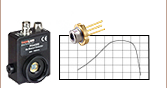
Click to Enlarge
Figure 1: Normalized Responsivities for the Camera Sensors in Each Wavefront Sensor Head
Sensor Head
Each sensor head (Item # Prefix: WFS31, WFS40, or WFS20) is based on a different CMOS camera. While the cameras provide different measurement performance, each wavefront sensor is operated using the same software application.
Camera Responsivity
The responsivities of the three cameras, which are similar, are plotted in Figure 1. The WFS20 sensor heads have higher relative responsivities at longer wavelengths and a flatter region of peak responsivity. The WFS31 sensor has higher relative responsivities at lower wavelengths.
Free Aperture and Camera Resolution
The maximum free aperture and camera resolution are coupled for these wavefront sensors. The WFS20 and WFS31 offer rectangular apertures, with the smaller dimension limiting the maximum diameter of incident circular beams. The WFS40 is approximately 30% larger along its sides compared to the WFS20 and WFS31; it provides a square aperture that accepts an input beam of up to Ø11 mm.
Operating Modes and Measurement Speed
Wavefront sensors that include the WFS31 or WFS40 sensor heads can operate in Normal Mode or the sub2 (subsampling) Mode. There is no High-Speed Mode option offered for these sensor heads. The entire spot field image acquired by the camera is transmitted to the PC in both operating modes. When operating in sub2 Mode, the frame rate is increased by using a single pixel from each 2 x 2 set of pixels for the calculation of focal spot centroids. The drawback is wavefront measurements with reduced accuracy.
The camera included with the WFS20 operates at faster speeds than the cameras that are included in the WFS31 and WFS40. Thorlabs takes advantage of the WFS20's faster camera by offering three operating modes: Normal Mode, 2 x 2 Binning Mode (Bin 2), and High-Speed Mode.
In the WFS20's normal mode, the frame rates are limited by the time needed to transmit the full spot field image from the camera to the PC, as well as by the time required to perform the calculations.
The faster 2 x 2 Binning mode improves the WFS20's frame rates by reducing calculation time. Instead of using the data from every pixel in the active area to calculate the focal spot centroids, the average value for the four pixels in every 2 x 2 set is used. The drawback is reduced spatial wavefront resolution.
In the WFS20's High-Speed Mode, the focal spot centroids are calculated by the fast field-programmable gate array (FPGA) built into the WFS20's Control Box. Not only can the FPGA calculate the spot centroids more quickly than the PC, but only the spot centroid data points are transmitted to the PC. This greatly decreases the amount of data that needs to be transferred to the PC, providing the fastest measurement speeds. A drawback is that it is not possible to view or manipulate the camera image in the GUI during operation in High-Speed Mode, which makes it harder to detect certain errors, such as those caused by camera saturation.
Physical Dimensions and Mounting Options
WFS20 sensor heads include both a sensor head and a control box, while the WFS31 and WFS40 options have only a sensor head. In addition, the dimensions of the WFS20 sensor head (46.0 mm x 56 mm x 33.1 mm) are larger than the common dimensions of the WFS31 and WFS40 sensor heads (35.4 mm x 29.8 mm x 42.6 mm).
All include an SM1A9 adapter for converting the external C-Mount to Internal SM1 (1.035"-40) threads, so that lens tubes can be used to reduce scattered light and neutral density filters can be used to prevent device saturation. The WFS20 also has three 8-32 (M4) taps on the bottom of the housing for mounting on Ø1/2" posts and four 4-40 taps on the front face for compatibility with Thorlabs' 30 mm Cage Systems. The WFS31 and WFS40 include a bottom-mounted adapter plate with an 8-32 (M4) and a 1/4"-20 (M6) tap for mounting the sensor head on Ø1/2" posts.
| Microlens Array Key Specificationsa | |||||||||
|---|---|---|---|---|---|---|---|---|---|
| Item # Suffix | Mask or Coating | Wavelength | Lenslet Pitch | Lenslet Size | Reflectivity | High Spot Contrast |
High Wavefront Accuracy |
High Spatial Resolution |
Low Back Reflection |
| -5C | <25% | - | - | ||||||
| -7AR | AR Coating | 400 - 900 nm | 150 µm | Ø146 µm | <1% | - | - | ||
| -14AR | 400 - 900 nm | 300 µm | 295 µm x 295 µm | <1% | - | - | |||
Microlens Arrays
The choice of microlens array affects frame rates and the quality of the wavefront measurement.
Chrome Mask vs. Anti-Reflection (AR) Coating
The chrome mask is a grid that frames each microlens. The mask blocks light from being transmitted unless it passes through a microlens, which increases image contrast. However, the reflections from MLA back to the source are high. The specified wavelength range is equal to that of the quartz substrate.
The AR Coating reduces the back reflections from the MLA within the specified wavelength range. The specified reflectivity of the AR coated MLA is valid only within the stated wavelength range.
Outside of this wavelength range, the reflectivity may increase significantly. Note that the total reflectivity of the instrument may be higher due to reflections from the CMOS camera chip and its window.
Lens Pitch
An MLAs lens pitch defines the distance measured from the center of a lens to the center of the lens next to it. So, MLAs with a 150 µm lens pitch offer a larger number of spots and thus a higher spatial resolution of the wavefront, and a wider wavefront dynamic range because of their shorter focal length. The MLA with a 300 µm supports higher wavefront accuracy and sensitivity at the expense of dynamic range and spatial resolution.
Frame Rates
Frame rates depend on the sensor head, operation mode, and microlens array and scale with the number of focal spots, as is discussed in the preceding. The frame rates for each combination of sensor head, microlens array, operation mode, and spot count are plotted in Figures 2 through 4.

Click to Enlarge
Figure 2: Frame Rates of Wavefront Sensors with Item # Prefix WFS31
Click to Enlarge
Figure 3: Frame Rates of Wavefront Sensors with Item # Prefix WFS40

Click to Enlarge
Figure 4: Frame Rates of Wavefront Sensors with Item # Prefix WFS20
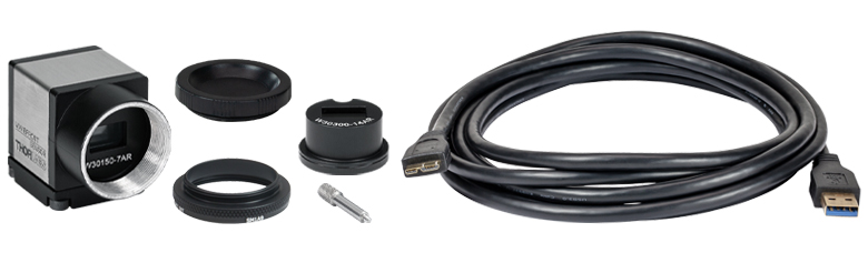
General-Purpose Wavefront Sensor

Click to Enlarge
WFS31-5C Package Contents
- General-Purpose Sensor Head
- Item # Specific MLA Installed on Sensor Head
- WFS31-5C(/M): MLA with Chrome Mask and 150 µm Lenslet Pitch
- WFS31-7AR(/M): MLA with Anti-Reflection Coating and 150 µm Lenslet Pitch
- WFS31-14AR(/M): MLA with Anti-Reflection Coating and 300 µm Lenslet Pitch
- SM1A9 Adapter
- Dust Cap
- USB 3.0 Type-A to Mini-B Cable, 3 m
- Quick-Start Guide (Not Shown)
General-Purpose Wavefront Sensor Kit
Click to Enlarge
WFS31-K2 Package Contents
- General-Purpose Sensor Head
- Item # Specific MLA Installed on Sensor Head
- WFS31-K1(/M): MLA with Chrome Mask and 150 µm Lenslet Pitch
- WFS31-K2(/M): MLA with Anti-Reflection Coating and 150 µm Lenslet Pitch
- Additional MLA, with Anti-Reflection Coating and 300 µm Lenslet Pitch, Packaged Separately
- SM1A9 Adapter
- Dust Cap
- Tool to Facilitate MLA Exchange
- USB 3.0 Type-A to Mini-B Cable, 3 m
- Quick-Start Guide (Not Shown)
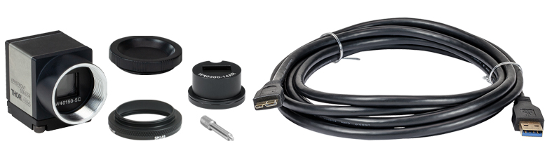
Large-Aperture Wavefront Sensor

Click to Enlarge
WFS40-14AR Package Contents
- Large-Aperture Sensor Head
- Item # Specific MLA Installed on Sensor Head
- WFS40-5C(/M): MLA with Chrome Mask and 150 µm Lenslet Pitch
- WFS40-7AR(/M): MLA with Anti-Reflection Coating and 150 µm Lenslet Pitch
- WFS40-14AR(/M): MLA with Anti-Reflection Coating and 300 µm Lenslet Pitch
- SM1A9 Adapter
- Dust Cap
- USB 3.0 Type-A to Mini-B Cable, 3 m
- Quick-Start Guide (Not Shown)
Large-Aperture Wavefront Sensor Kit
Click to Enlarge
WFS40-K1 Package Contents
- Large-Area Sensor Head
- Item # Specific MLA Installed on Sensor Head
- WFS40-K1(/M): MLA with Chrome Mask and 150 µm Lenslet Pitch
- WFS40-K2(/M): MLA with Anti-Reflection Coating and 150 µm Lenslet Pitch
- SM1A9 Adapter
- Dust Cap
- Tool to Facilitate MLA Exchange
- Additional MLA, with Anti-Reflection Coating and 300 µm Lenslet Pitch, Packaged Separately
- USB 3.0 Type-A to Mini-B Cable, 3 m
- Quick-Start Guide (Not Shown)
High-Speed Wavefront Sensor
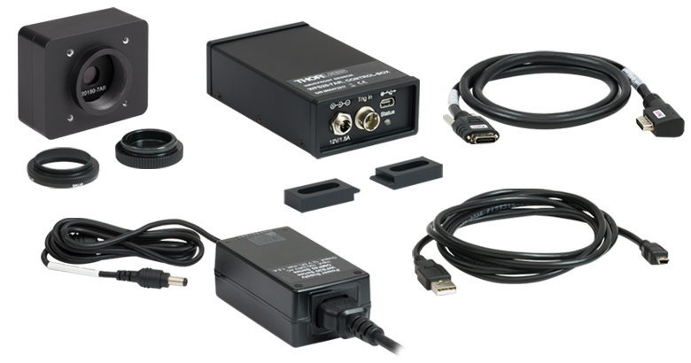
Click to Enlarge
WFS20-7AR Package Contents
- High-Speed Sensor Head
- Item # Specific MLA Installed on Sensor Head
- WFS20-5C(/M): MLA with Chrome Mask and 150 µm Lenslet Pitch
- WFS20-7AR(/M): MLA with Anti-Reflection Coating and 150 µm Lenslet Pitch
- WFS20-14AR(/M): MLA with Anti-Reflection Coating and 300 µm Lenslet Pitch
- Control Box
- PoCL Cable to Connect Sensor Head and Control Box
- SM1A9 Adapter
- Dust Cap
- Two Clamps to Secure Control Box
- Power Supply with Location-Specific Plug, 12 V and 1.5 A
- USB 2.0 Type-A to Mini-B Cable, 2 m
- Quick-Start Guide (Not Shown)
High-Speed Wavefront Sensor Kit
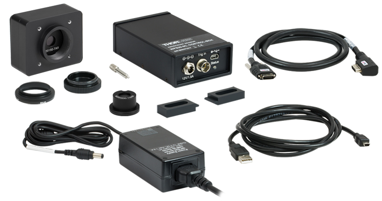
Click to Enlarge
WFS20-K1 Package Contents
- High-Speed Sensor Head
- Item # Specific MLA Installed on Sensor Head
- WFS20-K1(/M): MLA with Chrome Mask and 150 µm Lenslet Pitch
- WFS20-K2(/M): MLA with Anti-Reflection Coating and 150 µm Lenslet Pitch
- Additional MLA, with Anti-Reflection Coating and 300 µm Lenslet Pitch, Packaged Separately
- Control Box
- PoCL Cable to Connect Sensor Head and Control Box
- SM1A9 Adapter
- Dust Cap
- Tool to Facilitate MLA Exchange
- Two Clamps to Secure Control Box
- Power Supply with Location-Specific Plug, 12 V and 1.5 A
- USB 2.0 Type-A to Mini-B Cable, 2 m
- Quick-Start Guide (Not Shown)
Software
Version 6.1 (January 3, 2024)
The wavefront sensor software package for:
- Windows® 10 or 11 (32 or 64 Bit)
- WFS31 Series
- Windows 7, 8.1, 10 or 11 (32 or 64 bit)
- WFS20 or WFS40 Series
Software Download
Click on the Software button to the right for the latest version of Thorlabs' Shack-Hartmann Wavefront Sensor Software Package. The download includes the software package with a graphical user interface for operating the WFS in standard applications and support for developers who want to extend or adapt the functionality of the device to their special requirements.
System Requirements:
- Windows® 10 or 11 (32 or 64 Bit)
- WFS31 Series
- Windows 7, 8.1, 10 or 11 (32 or 64 bit)
- WFS20 or WFS40 Series
- USB Interface
- WFS20 Series: USB 2.0 or 3.0 Port
- WFS31 or WFS40 Series: USB 3.0 Port
- Graphic Card: 256 MB Memory (Min, Shared)
- Graphic Resolution: 1024 x 768 Min, 1280 x 1024 Recommended
- Free Storage Space: 500 MB (Min)
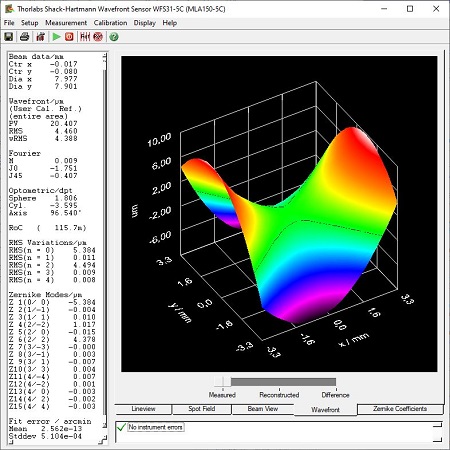
GUI Display of Measured Wavefront
Software and Graphical User Interface
Display/Output Options
For screen images of the GUI display options, please click on the links:
- Raw Spotfield Image
- Zernike Coefficients
- Measured and Reconstructed 3D Wavefront
- Irradiance Distribution
- Lineview Intensity of Pixel Column
- Tabulated Output
- Flexible Export Option: Text or Excel File
- Live Data Readout via TCP/IP to a DataSocket Server
Calculated Parameters
- Beam Centroid and Diameter
- Modal and Zonal Reconstructed Wavefront
- Max Variance of Wavefront, Peak-to-Valley (PV), and RMS of Wavefront
- Zernike Representations of Tilt, Defocus, Astigmatism,
Coma, Spherical, and Higher Order Aberrations - Fourier and Optometric Parameters
Included Drivers
The software includes a driver package for constructing custom applications with the following software packages:
- C Compilers
- LabWindows™/CVI
- LabVIEW®
- .Net
| Posted Comments: | |
user
(posted 2024-04-10 10:37:21.877) Hello, I have a similar problem as described before. After software installation, the Wavefront Sensor software opens and closes after couple of seconds with or without having a connected camera. I use Windows 10. hkarpenko
(posted 2024-04-10 12:04:18.0) Dear customer,
thank you for your feedback. I will contact you directly to discuss this issue further with you. Michael Deyerler
(posted 2024-03-13 10:17:31.027) WFS31-5C/M is not recognized with newest SW version.
An old WFS150-5C is recognized without issues.
please advice dpossin
(posted 2024-03-13 06:42:24.0) Dear Michael,
Thank you for your feedback. I reach out to you in order to provide assistance. Marco Smarra
(posted 2024-01-18 08:54:56.077) Unfortunatly, I cannot start the software on my windows 11. The software pops-up and closes within 5 seconds. This happens with and without camera connected to the usb port. Reinstallation does not change this behaviour.
Using the compability mode for Win 7 does not change this behaviour, either.
Do you have any suggestions for me?
Thanks for your help. GBoedecker
(posted 2024-01-18 09:25:13.0) Thank you for your feedback! The Wavefront Sensor software was tested successfully on Windows 11. I will contact you directly for troubleshooting. yujie lu
(posted 2023-11-23 16:15:56.07) Does this product delivery list include sensor power supplies ? dpossin
(posted 2023-11-28 05:56:17.0) Dear Customer,
The shipping list can be seen here: https://www.thorlabs.de/newgrouppage9.cfm?objectgroup_id=5287&tabname=shipping%20list.
The WFS is powered by the USB connection. yujie lu
(posted 2023-11-23 16:13:20.34) 1. How long is the delivery time of this product When can it be shipped ?
2. Are there other alternatives available in stock that can be used to connect WFS31-14AR / M and external trigger power supplies? dpossin
(posted 2023-11-28 05:59:42.0) Dear customer,
Thank you for your feedback.
1). Somebody from our sales team in china will get in contact with you regarding the lead time.
2). We don´t have any alternatives. Yonghe Li
(posted 2023-10-30 17:10:42.747) Hello, I have one WFS31-14AR Shack-Hartmann Wavefront Sensor. During testing it, I found it turned very hot. Is it common? Or there is something wrong with my device? hkarpenko
(posted 2023-11-02 04:54:05.0) Dear customer,
thank you for your feedback. It is not unusual, that the device itself and the control box get hot during long term operation. I will contact you directly to discuss this issue with you. 磊 葛
(posted 2023-10-24 12:45:34.56) 是否可以借测? fmortaheb
(posted 2023-10-25 04:44:06.0) Thank you very much for contacting Thorlabs. We will contact you directly to discuss the possibilities and your application. user
(posted 2023-10-13 15:31:30.723) I'm trying to use the Labview drivers to write my own programs, specifically the VIs get spot intensities and get spot to reference deviations. I noticed that the output of these arrays are length 8000, and is a constant in the block diagram. The length does not correspond to the dimensions of the MLA or pixels, so how do we know which lenslet the index corresopnds to? GBoedecker
(posted 2023-10-19 07:58:30.0) Thank you for your feedback! The one-dimensional array should be reshaped in Labview to a two-dimensional array of size 80 x 80 which is the maximum number of spots. The Labview example in C:\Program Files (x86)\National Instruments\LabVIEW\instr.lib\TLWFS should help to figure out the details. Yutaka Yamagata
(posted 2023-09-01 13:59:47.02) We have wavefront sensor WFS150-7AR, but the device driver cannot be installed on 64bit Windows11 system. Is there any way to let this device work on windows11? GBoedecker
(posted 2023-09-05 08:31:25.0) Thank you very much for your feedback! If the WFS150-7AR is not recognized on Windows 11, you can install the driver manually. I will contact you directly to assist with the details. Steve JANG
(posted 2023-02-16 17:19:23.213) I have WFS20-7AR products, I have questions on "Certification of calibration"
There is test source S1FC635 and below there is 3 masured values "Collimated 6.6mm diameter" "divergent RoC 475.2mm" 'divergent RoC 3039.8mm "
Can I get futher information on the meausurement values?
1) what condition for the each measured values - what source (or lens) is applied for each measurement?
2) why the "collimated" value has only diameter values? wskopalik
(posted 2023-02-22 04:49:37.0) Thank you very much for your feedback!
The collimated as well as the divergent beams are used to adjust the WFS sensors.
When a point light source is used, the RoC values shown by the WFS correspond to the exact mechanical distance between the WFS and the point light source. The divergent beam is measured at two defined distances to make sure that the RoC values are measured correctly by the WFS sensor.
The 6.6 mm are the beam diameter of a collimated beam that is used to align the microlens array mounts with respect to the camera sensor. The goal is to illuminate the sensor chip as completely as possible. The fiber collimator F810FC-635 is used for that.
I will contact you directly to provide further information. Mohammadhossein Khosravi
(posted 2023-02-01 13:01:25.307) Dear Thorlabs,
I am using WFS30 to measure the RoC of a beam coming out of a fiber in short distances from fiber end (50-400um). As a result, I am using a microscope setup and placed the wavefront sensor at the imaging plane.
I cannot find the relation between the RoC from sensor (which comes from the magnified beam) and the demagnified beam. Would you please help me with my issue?
Best,
Mohammad wskopalik
(posted 2023-02-02 11:19:34.0) Thank you very much for your feedback!
The influence of the microscope setup on the beam and on the RoC depends on the design of the setup, e.g. the used optics.
I will contact you directly so we can discuss the setup in more detail. Daren Trinh
(posted 2022-11-02 17:12:15.583) Hi, do you guys have a solution for Linux? We want to be able to use the WFS20-5C with a Raspberry Pi and the Raspbian OS. GBoedecker
(posted 2022-11-03 11:30:06.0) Thank you very much for contacting Thorlabs. We do not currently have a solution for Linux, but we might be able to provide some help. I will contact you directly to discuss this further. Cash Wu
(posted 2022-10-26 15:41:30.67) Hello , I have two WFS20-5C/M . I used beamview to pre-adjust the optical path of the machine, but the old WFS20-5C/M and the new WFS20-5C/M showed different effects. What parameters can I try to adjust? fmortaheb
(posted 2022-11-02 10:16:28.0) Thank you very much for contacting Thorlabs. I will contact you directly to discuss your application in more detail. user
(posted 2022-08-31 08:57:50.587) Hello, I have a WFS40 and I would like to acquire spot field images, save them and later calculate the wavefront for a whole set of different evaluation parameters (e.g. pupil diameter and position) using your reconstruction tools.
To do this, I would like to use python (with third-party python bindings) with which I have already successfully taken spot field images, calculated the spots, deviations and finally the wavefront. However, it is not clear to me if (and how) I can load a previously saved spot field image. Thank you very much for your support. wskopalik
(posted 2022-09-01 08:40:32.0) Thank you for your feedback!
It is unfortunately not possible to load recorded spot field images and evaluate them with the WFS driver files. You can only evaluate the spot field image which is in the buffer of the WFS driver directly after the recording (functions “WFS_TakeSpotfieldImage” / “WFS_TakeSpotfieldImageAutoExpos”). Once a new image is recorded, the buffer is filled with the new image data and the previous image can no longer be evaluated.
I will contact you directly to provide further assistance. Homan CHAN
(posted 2022-06-30 15:01:26.3) Hi Thorlabs,
Here is Jabil.
We need help about the installation driver software & app software for USB3.0 digital camera. Actually we had tried this kind of software from this link (https://www.thorlabschina.cn/newgrouppage9.cfm?objectgroup_id=5287) but not work .
Details Info: USB3.0 digital camera , of which its full name is that ' uc480 cmos,1280x1024,gs,1/2 usb3 camera '.
Hope your reply.
Many thanks.
BR
Homan AURELIEN PELLEAU
(posted 2022-06-22 13:49:16.0) Hello,
I am currently developing software with labview to use the WFS-40. I can't understand the WFS_set_calc_spot_to_user_reference.vi function,
The description of the input parameters tells us that we can connect a 2D array for the X and Y positions, but the function does not accept arrays as input, only numbers.
How should we use this function?
Thank you for your answers, Aurélien wskopalik
(posted 2022-06-28 03:45:58.0) Thank you very much for your feedback!
I will look into this issue and will contact you directly to provide further assistance. Paul Nachman
(posted 2022-06-13 18:41:10.987) I have a question actually about the WFS30-14AR. (I know it's not currently available, but we already have one in Brian D'Urso's group at Montana State University.)
We're interested in working with the raw data. From page 79 of the manual ...
https://www.thorlabs.com/drawings/84eb0090a3bdf516-8380AC00-A070-E3A1-2133F91355515A5F/WFS20-14AR_M-Manual.pdf
... I deduce that there should be **two** arrays of raw deflection numbers, one for "x" values and the other for "y" values. (Each array should have the same number of elements as in the microlens array, 35 x 21.)
But we seem to have access only to one such array. And it's not clear which one.
Please clarify.
Paul Nachman
Affiliate Research Professor of Physics
Montana State Univeristy
Bozeman wskopalik
(posted 2022-06-16 10:20:35.0) Thank you very much for your feedback.
The DataSocket interface which is described on p. 79 in the manual can return two types of raw data arrays:
One type is the “Wavefront” array which contains one deformation value for each microlens. This is basically the deformation of the wavefront in Z direction and corresponds to the data shown in the wavefront panel in the GUI.
The other type are the two arrays “Centroid_Pos_X” and “Centroid_Pos_Y” which contain the centroid positions of the spot for each microlens. So in this case you have one X and one Y value for each microlens.
I will contact you directly to provide further information and assistance. Paul Nachman
(posted 2022-04-27 20:08:37.767) I've just been acquainting myself with the WFS30-14AR we have in Brian D'Urso's research group in the Montana State University Physics Department. It's working fine in measurements of beam curvature for a beam emerging from a one-micron-diameter pinhole (beam-power level about 20 microwatts at 520 nm).
What concerns me is that the device's casing gets quite warm ... maybe even HOT. Is this a problem? (In general, heat is bad news for electronics, no?)
Because of this, I'm disconnecting the USB 3.0 Micro-B Connector dedicated cable from the computer's fast USB port when the camera's not in use. Does this make sense, or is there some issue with repeated connecting and disconnecting? dpossin
(posted 2022-05-02 09:10:57.0) Dear Paul,
Many thanks for your feedback! Well the casing of the WFS can get warm due to the microlens array absorbing light. This does not neccessarily point to a malfunction. However it makes sense to double check in case there is a concern from your side. Repeatedly disconnecting and connecting does not harm the WFS at all. I am reaching out to you in order to discuss the details of your setup. John Mitchell
(posted 2021-11-15 10:27:38.367) We have a requirement to perform wavefront measurements (low order aberrations) in a challenging environment (inside an environmental chamber) of an imaging system. Interferometry is proving difficult (low level vibrations, maintaining alignments etc.). We are thinking of employing a S-H sensor with a beamsplitter and a point source conjugate to the detector, along with a return mirror to measure the system in double pass.
We wonder whether you could comment on the suitability of your S-H sensors for this application (are there any application notes?) Would there be any prospect of an evaluation loan to trial the usefulness prior to purchase?
Many thanks,
John soswald
(posted 2021-11-17 09:11:03.0) Dear John,
thank you for your feedback. I have reached out to you directly to discuss your application in more detail. Mark Denninger
(posted 2021-08-25 10:44:39.473) I have an older model, WFS150-5C, which appears to suffer from a similar problems as previously described: program loose connection to camera after app. 10 to 15 sec. Several different USB cables tested as well as all available ports on PC. PC is running Win10. Latest WFS software downloaded and installed. Please advice. MKiess
(posted 2021-08-31 05:55:31.0) Dear Mark, thank you for your inquiry. This may be related to the USB connection. It is best to use the supplied USB cable. I have contacted you directly to discuss further details. Jon Twichell
(posted 2021-08-20 15:35:07.483) 1) Shack Hartmann wavefront sensors actually measure the centroid of the lenslet focal spot, and use this and the focal length (and the reference wavefront) to calculate the wavefront GRADIENT, the tip/tilt of the wavefront at each individual lenslet. The calculation of the true wavefront (or Zernike functions) requires a translation of the wavefront gradients (and possibly intensities) to the wavefront, a process called reconstruction. There are many ways to perform reconstruction. Usually, one adopts a "minimum RMS error" criteria but this approach usually involved using just the centroid positions. There are intensity weighted reconstruction algorithms which, in principle, give better results than just phase reconstruction. Can you provide details (perhaps references) to the technique(s) employed in your software?
2) how do you resolve the "checkerboard" isolation of gradient nets in your sensor. Just assume it is zero?
3) The measure of tip and tilt is vitally dependent on the reconstruction algorithm used. Given the huge number of redundant measures of tip and tilt present in the gradient array, the beam tip/tilt measure should be extremely accurate. If it is not, there is a problem with your reconstruction algorithm.
4) Several alignment aids are often useful in setting up a wavefront sensor. Having a real-time readout of Tip and Tilt averaged across the aperture, and displayed in a large format (so it can be seen across the bench) is handy, as is a similar measure of "focus", a second moment in both X and Y. An intensity map also helps as a sanity check, and to assist in aligning the beam to the sensor axis.
5) I would expect some form of propagation to the far field calculation, and a calculation of the resulting Strehl ratio, which should be far better than most simpler measures of beam quality. You could also calculate "flux in a bucket" plots to help evaluate the impact of high order aberrations.
6) are there third party applications to fill in some of the limited functionality of the present software?
Many thanks,
Jon wskopalik
(posted 2021-08-30 11:08:43.0) Thank you very much for your feedback!
I will contact you directly so we can discuss your questions in more detail. Dong IL Lee
(posted 2021-08-17 16:33:15.667) Dear Thorlabs company,
I am trying to use the WFS20-7AR with NI LABVIEW.
Can you provide an example of LABVIEW program?
Thank you MKiess
(posted 2021-08-19 09:18:26.0) Dear Dong IL Lee, thank you very much for your inquiry. A NI LabVIEW example including the drivers is included in the software download and can be found in the following folder:
C:\Program Files (x86)\National Instruments\LabVIEW xxxx\......Instr.lib\WFS\WFS.llb
"LabVIEW™ xxxx" stands for actual LabVIEW™ installation folder. carlos Reyes
(posted 2021-07-30 05:36:01.95) Hello,
I've been acquiring wavefront data with the provided Labview VI. I was wondering if it is possible to average the wavefronts when acquiring similar as in the 'setup wavefront sensor" from the other thorlabs software, e.g., 1, 30, 100, 100 roll etc?
Thanks
Carlos wskopalik
(posted 2021-08-04 10:57:04.0) Thank you very much for your feedback!
Yes, you can also average the wavefront images in LabVIEW. The averaging is a function in the driver which is also available in the LabVIEW VIs. The VIs you can use are “WFS Average Image.vi” and “WFS Average Image Rolling.vi” for standard and rolling average.
I will contact you directly to provide further information. user
(posted 2021-06-23 09:53:15.94) In the manual, you mention that the wavefront is calculated with respect to the reference plane. I think, however, that the _beam_ centroid location is calculated with respect to the camera sensor. Am I correct on this?
If so, what is the distance to the camera sensor to the c-mount flange? 17.526mm?
Thank you! wskopalik
(posted 2021-06-28 10:08:28.0) Thank you very much for your feedback!
The microlens array is the reference plane for all the measurements on the WFS sensors. It is correct that the actual detection of the spots takes place on the camera chip behind the array. But the measured deformations as well as the beam parameters are all calculated so they correspond to the reference plane.
The C-mounts on these cameras have the standard dimensions, i.e. 17.526 mm from C-mount flange to camera chip is correct.
I will contact you directly to provide further assistance. Zhou Xing
(posted 2021-06-11 17:31:16.547) "There is no Wavefront Sensor connected to the computer."
I tried with two computers, and both of them had this problem.
When I was updating the driver for the installation device, I encountered an error trying to install the driver: Windows stopped it because of a problem with the device. wskopalik
(posted 2021-06-16 07:32:44.0) Thank you very much for your feedback!
I will contact you directly so we can find a solution for this issue. user
(posted 2021-05-12 02:01:17.577) Hi, please supply me with Python code for interfacing with the Thorlabs wavefront sensor driver.
Thanks and kind regards, Francois MKiess
(posted 2021-05-14 05:52:45.0) Thank you for your inquiry. I have contacted you directly to provide further information and assistance. JO Wit
(posted 2021-02-25 03:20:13.383) Hi, this is Jo de wit from ASML; I'm interested in your Shack Hartmann wavefront sensor. I have a question about WFS30-5C: in the spec's you mention Nominal focal length = 5.6[mm]; and Effective focal length (Typical when mounted in WFS) = 4.1[mm]. My question is: can you explain this difference? And does it mean that the camera in this WFS is NOT at the distance of the nominal focal length from the micro lens array? Why is that?
Thx for your comments, JO soswald
(posted 2021-02-25 10:49:46.0) This is a response from Soenke at Thorlabs:
Dear Jo,
thank you for your feedback.
The focal length of microlens arrays is difficult to define due to diffraction effects in the microlenses.
The microlenses are manufactured with a certain radius and using the lensmaker's equation one can calculate a theoretical focal length for them, which are the 5.6 mm nominal focal length we specify.
In reality when aligning the micro lens arrays to our wavefront sensors we found that the smallest focal spots are achieved at 4.1 mm distance for the WFS30-5C, which we specify as the effective focal length. TC Chua
(posted 2021-02-23 16:40:40.24) Hi, can you provide me with the python example for WFS30-14AR please? MKiess
(posted 2021-02-25 08:38:47.0) Thank you for your inquiry. I have contacted you directly to discuss further details to provide further assistance. Jaedeok Park
(posted 2020-12-10 04:26:04.773) Hellow, I am Jaedeok Park in Ajou university, South Korea.
While I using the wavefront sensor WFS30-5C gladly, I want to make some application with this product. So I try to find the SDK to arrange the software for my purpose. However, I can not find any SDK of WFS30-5C, only the complete software for the sensor I found.
Would you present a SDK for Labview vi. of WFS30-5C? Or is there no SDK for WFS30-5C?
Sincerely,
Jaedeok Park wskopalik
(posted 2020-12-11 10:22:51.0) Thank you very much for your inquiry!
The installation package of the WFS software includes an SDK as well as example codes and documentations for different programming languages and environments including LabVIEW. In section 6 of the manual ("Write Your Own Application") you can find the paths and folders where the files are saved on the computer.
The LabView VIs are usually saved to the "instr.lib" folder which is a subfolder of the LabVIEW folder.
I will contact you directly to provide further assistance. WENQI OUYANG
(posted 2020-11-02 22:52:08.92) Hello, I have a question about the use of WFS40-7AR/M: What should be the range of light intensity by a femtosecond laser, with a repetition rate of 1kHz and pulse width ~120fs? Thanks so much. dpossin
(posted 2020-11-03 10:10:47.0) Dear Wenqui,
Thank you for your feedback. Basically the damage treshold depends on the average power and the beam diameter of your laser. I am reaching out to you in order to discuss your application more in detail. Nicolas Dubost
(posted 2020-10-23 06:03:45.33) Hello,
I just installed all the software for the WFS150-7AR. When I start the software, I manage to connect to the WFS, but after a few seconds (not more that 10), I always loose connection. My colleagues tell me this has been happening for some time now. Some suspect it might be the USB cable, but after trying with different cables the problem persists. What could it be?
Thanks soswald
(posted 2020-10-27 08:02:03.0) Dear Nicolas,
thank you for your feedback. This issue can have a number of different reasons from the USB cable to the USB connectors on the WFS or your computer as well as potentially a USB hub. I have reached out to you to discuss this further. Sebastien Garcia
(posted 2020-10-23 02:36:25.83) Hello,
I have two questions :
1) Could you give in the specs tab the reflectivity of the AR coating of the MLA between 300nm and 1100nm?
2) I do not completely understand the interest of the chrome masked coating relitve to the AR coating. I the selection guide you say that the spot contrast is better, but in the specs the wavefront sensitivity is lower. Can you explain what is the interest of a high spot contrast for the measured wavefront characteristics? wskopalik
(posted 2020-10-26 07:35:34.0) Thank you very much for your feedback!
The AR coating has a reflectivity of <1% in the range of 400 nm - 900 nm. A typical diagram is shown in the manual. Outside of this range the reflectivity can increase considerably. Especially below 400nm the reflectivity will increase to 5% and more.
The microlenses in the 5C-version of the wavefront sensors are round and arranged in a square pattern, which creates flat areas in between the lenses. In these areas the light could pass directly through the array substrate, which would cause unwanted stray light patterns on the camera chip. The chrome mask is therefore added to block this light, which increases the image contrast, i.e. the actual microlens spots are better separated from the background noise and therefore easier to detect.
The sensitivity on the other hand is mainly determined by the effective focal length of the microlenses. As the 7AR-version has a slightly longer focal length than the 5C-version, the sensitivity is a bit better on this version as well.
I will contact you directly so we can talk about all this in more detail. JUSTO ARINES
(posted 2020-10-15 06:16:55.473) Why a positive RoC represents a divergent beam ?
The Zernike coefficients are for phase or for optical path difference ? wskopalik
(posted 2020-10-20 06:54:59.0) Thank you very much for your feedback!
The Radius of Curvature (RoC) is equal to the distance in air between the reference plane of the WFS sensor and the point source of a spherical wavefront. The direction in which the WFS sensor looks is defined as the positive direction, behind the WFS sensor is the negative direction. For a divergent spherical wavefront where the point source is located in front of the WFS sensor, the RoC is therefore positive. For a convergent/focussed spherical wavefront where the virtual focal point lies behind the WFS sensor the RoC is negative.
The Zernike coefficients represent the deformation of the incident wavefront. For a continuous wavefront this can also be interpreted as a phase difference between different locations within this wavefront. This can e.g. be caused by an optical path difference.
I have contacted you directly to talk about your questions in further detail. David Kranz
(posted 2020-07-08 19:17:34.573) Hello,
There is dust trapped between the outside window and detector cover glass causing spikes in the wavefront. Do you have white paper tutorial showing how to clean the wavefront camera. wskopalik
(posted 2020-07-09 06:12:04.0) This is a response from Wolfgang at Thorlabs. Thank you very much for your feedback!
Dust can be removed by using compressed gas which is free of oil and water. For example Thorlabs Duster CA4-US or CA4-EU can be used. Please make sure to keep the gas nozzle at least at a distance of 4 inches / 10 cm from the surfaces to prevent liquid gas drops hitting the surfaces and leaving visible traces on them.
I will contact you directly to provide further assistance. Farhad Akhoundi
(posted 2020-06-19 13:27:59.15) Hi,
There is a bug in your Shack Hartman Software that I wanted to let you know.
The sign of the Z6 (Zernike coefficient) is opposite which makes it the reported optometric values wrong as well.
To test this you may use a concave cylindrical wavefront and observe the result.
Regards, wskopalik
(posted 2020-06-29 09:52:28.0) This is a response from Wolfgang at Thorlabs. Thank you very much for your feedback!
We will look into this issue in the WFS software. I have already contacted you directly and will keep you updated about our findings. user
(posted 2020-05-14 05:37:13.217) Hi,
I have been unable to install the wfs sw for wfs40 on win10 64 on dell precision 7530.
I get a C++ runtime error, and haven't been able to work around it. I've updated C++ redistributable, dell drivers. Older versions of wfs don't install either. Also give runtime error.
I also installed thorcam sw and it works perfectly with a
cs505mu I also have in the lab.
Pls advise. MKiess
(posted 2020-05-18 05:49:12.0) This is a response from Michael at Thorlabs. Thank you very much for your inquiry. I have contacted you directly to provide further assistance. David Gay
(posted 2020-05-13 09:27:46.223) Hi,
On your web site, in the selection guide tab, the graph does not show the relative sensitivity of the WFS40 at 1064 nm. Using the WFS40 with the chrome mask, should we be able to characterize a laser beam at 1064 nm with a 5mm-diameter Gaussian profile ? The laser will run either in cw or in pulsed mode (10 ns pulses at > 10 kHz)
Thank you wskopalik
(posted 2020-05-18 06:40:33.0) This is a response from Wolfgang at Thorlabs. Thank you very much for your inquiry!
Unfortunately, we don't have any data about the responsivity of the camera used in the WFS40 sensors from 1000 nm on. But it can be used up to 1100 nm, so 1064 nm is fine. The responsivity will be quite low in this range, but you will most likely still need additional attenuation of the beam. As the beam is focussed by the microlenses to small spots, it is usually necessary to take measures which prevent saturation even in spectral ranges with low responsivity.
I will contact you directly to provide further assistance. Farhad Akhoundi
(posted 2020-03-16 15:51:21.55) I bought one WFS30-5C and it is working well. However, I wanted to ask you to replace the microlens array to a 300 um pitch and 5 mm focal length. This lens is not listed in your microlens array lenses but is commercially available in other companies. Please let me know if you do that.
Thanks wskopalik
(posted 2020-03-17 10:07:55.0) This is a response from Wolfgang at Thorlabs. Thank you very much for your inquiry.
The array with a pitch of 300µm which we offer as a standard in our wavefront sensors has been selected because this geometry of pitch and focal length gives a good performance regarding the accuracy and sensitivity of the measurements. For other geometries this performance might change.
I have contacted you directly so we can talk about the technical details and your requirements in more detail. laura maddalena
(posted 2020-03-05 10:40:43.63) Dear Madam/Sir,
I have your Shack-Hartman sensor (WFS 20). I would like to obtain raw images from it using python 3, do you have any SDK or suggestion to do this ?
Thanks.
Laura wskopalik
(posted 2020-03-06 09:47:54.0) This is a response from Wolfgang at Thorlabs. Thank you for your inquiry!
Thorlabs does not officially support Python for the wavefront sensors at the moment. But there are third-party solutions and examples available on the internet.
I will contact you directly with further information where you can find these. user
(posted 2020-02-26 03:46:26.44) Dear Thorlabs, One of the answers below it's told there is a python example. Could you please send me the python example? wskopalik
(posted 2020-02-27 09:10:46.0) This is a response from Wolfgang at Thorlabs. Thank you for your inquiry!
I will contact you directly with further information about this example. Sifiso Mpapane
(posted 2020-02-11 10:07:48.807) Dear Thorlabs: I a WFS from Thorlabs, I have been using it for the last 3 month now, mainly operating it using my laptop and it was connecting perfectly fine without issues. However, I have recently been experiencing problems with getting it to connect with with the same laptop I had used to operate it, where it now just give out the red led signal whenever I try to connect it. I then tried to operate it using a desktop PC, where it then gave the desired green light signal, but when I then tried to access the sensor from the software, the programme gives an error message saying it does not recognise the camera. Please assist me in resolving the issue raised, I will provide further details necessary that you might need at your request. Thank you. MKiess
(posted 2020-02-12 08:50:16.0) This is a response from Michael at Thorlabs. The red LED is an indication that the power supply of the WFS20 is not properly connected or that the wavefront sensor is not recognized correctly by the Windows system. Updating the software and drivers could make the device work normally again.
I have contacted you directly to discuss further details. user
(posted 2020-02-10 16:02:19.087) My application is logging Zernike coefficients from the wavefront sensor at specific time intervals. I would like to utilize the Data Socket function in your app. I wrote a client app in python to connect and listen to the DSTP port 3015, but I am not seeing any data. Is there a command that needs to be sent to tell it to send data? I don't see a function like that in your example receiver C code. Please let me know what command to send so it sends data back. MKiess
(posted 2020-02-12 07:17:01.0) This is a response from Michael at Thorlabs. Within the WFS application, you need to enable the transfer of the measurement data. Detailed explanations on this can be found in the manual which is available for download on our webpage.
After that is done, the data will be sent to the DataSocket server and any application can pull the data out. No additional command is required.
The correct data transmission can be checked by the WFS_Receiver application. If this application can receive the data, we might have to check your Python application.
I have contacted you directly to discuss the details. SB Wu
(posted 2019-11-05 03:47:22.687) 1. Are Shack-Hartmann Wavefront Sensors fit for measuring the light beam divergence?
2. Are Shack-Hartmann Wavefront Sensors also fit for non-coherent light, say LED, Xe lamp? dpossin
(posted 2019-11-06 04:33:22.0) Dear Customer,
Thank you for your feedback. The Shack-Hartman sensor is able to measure the radius of curvature (RoC) of the incident beam by the zernice polynomial Z5 (defocus). While a positive RoC represents an divergent beam, an negative RoC represents an convergent beam accordingly. However because an absolute planar wavefront would lead to an Z5 close to zero and to an infinite RoC accordingly, the degree of collimation can´t be measured with a high accuracy (see the manual page 49 for reference).
The Shack-Hartman sensor should be able to also detect the wavefront of incoherent beams. user
(posted 2019-10-30 14:37:42.41) Dear Thorlabs:
I have a WFS camera from Thorlabs and an iDS USB3.0 CMOS camera for iDS. Essentially, both are iDS cameras. However, the WFS and iDS software seem conflicting each other. If iDS suite is installed before WFS software, WFS camera will not be recognized in WFS software but iDS suite will recognize it. If WFS software is installed first before iDS suite, then iDS camera will not be recognized in iDS suite and, of course, can not be operated in WFS software either. Is there any way I can resolve the conflict between the two software/driver? Eventually, I'd like to operate both cameras on the same computer.
In addition, I am trying to use Python to control WFS camera. I noticed some examples were provided to earlier comments. Can you please provide some necessary information or guidance to me if it's available? Thank you very much. MKiess
(posted 2019-11-04 10:17:59.0) This is a response from Michael at Thorlabs. Thank you very much for your inquiry. If you want the WFS to be recognized as WFS you have to assign the Thorlabs drivers to the WFS.
To show how this works in detail and to send the necessary information for programming with Python, I contacted you directly. QiWei Zhou
(posted 2019-10-21 11:43:53.267) Dear Thorlabs, How to use the SDK of LabWindows™/CVI? Are there any examples or tutorials?Thank you. dpossin
(posted 2019-10-28 10:22:59.0) Dear Customer,
Thank you for your feedback. We do have C programming examples. You can find them under the following path once the software is installed: C:\Program Files (x86)\IVI Foundation\VISA\WinNT\TLPM\Example\C. Yeong Gyu Kim
(posted 2019-09-23 10:09:19.45) Dear Thorlabs,
One of the answers below says how to use Python. Please send me an python example. MKiess
(posted 2019-10-02 05:31:54.0) This is a response from Michael at Thorlabs. Thank you for the inquiry. I have contacted you directly to send you the necessary information. Yeong Gyu Kim
(posted 2019-09-20 17:58:04.753) Dear Thorlabs,
I am currently using the wfs20 model.
The program has a Raw Spotfield Image Save function.
Can I load my saved raw spotfield image to calculate the wavefront? MKiess
(posted 2019-10-01 08:38:58.0) This is a response from Michael at Thorlabs. Thank you very much for your inquiry! Unfortunately, it is not yet possible to load the saved raw spotfield image to calculate the wavefront. This is because the raw spotfield data saved in this program does not contain data of the Microlens arrays. Thus, the raw data cannot be loaded at another computer to calculate the wavefront. For this, we have to implement a corresponding function in the saving process. Thank you very much for this note.
Together we will find a solution for your application. I have contacted you directly for further discussions. Sebastian de Echaniz
(posted 2019-08-27 04:03:28.757) Hi, could you please tell me what is the saturation intensity of the WS30 and WS40? Thank you. dpossin
(posted 2019-08-28 09:51:19.0) Dear Sebastian,
Thank you for your feedback. We do not acually specify this value but the saturation should be somewhere in the pW area. The reason is that the focused spots generated by the microlens array have a relative high energy density while the CMOS chip inside the wavefront sensor has a high sensitivity. Jesús Palací López
(posted 2019-08-12 10:13:13.233) Hello!
I am trying to operate a WFS20-7AR unit using the LabVIEW SDK. When using the high speed mode I am not able to retrieve the centroids. What VIs should i be using? The ones retrieving the centroid are not compatible with high speed mode.
Also, is there a 2015 version of the SDK? I would like to integrate it with additional sw implemented in this version.
Many thanks fro your assistance!
Jesús dpossin
(posted 2019-08-21 09:46:49.0) Hello Jesús,
Thank you for your feedback. In the highspeed mode the centroid positions are saved on the FPGA chip of the camera but it is still possible to read them out. Therefore you need to execute the "Take Spotfield Image" function to retrieve the actual centroid data. The centroid positions can be read out then by using the command "Get Spot Centroids. According to your second question, you can download older versions of the WFS Software from our website here: https://www.thorlabs.com/software_pages/ViewSoftwarePage.cfm?Code=WFS. Just navigate to the tab called "Archive" and choose the WFS Software Version 4.5. Przemyslaw Gontar
(posted 2019-07-11 07:51:45.263) Hello, I'm trying create my own WPF app in c# in visual studio. I rely on your c# console application code but failed. Can you send me an example of a simple WPF in c# application using a wavefront sensor? swick
(posted 2019-07-23 04:13:02.0) Response from Sebastian at Thorlabs. In principle, it is possible to integrate the WFS into WPF applications. A possible approach for the integration is to use the WPF template in Visual Studio and the C# sample of the WFS for the background logic of the application. You would then need to connect the elements from the interface with the output values of the background logic. I contacted you directly to provide assistance. user
(posted 2019-05-29 14:17:25.31) This is Lei Li from Washington State University. We want to purchase a Shack-Hartmann WFS. Could you give me three separate quotes for:
WFS30-5C, WFS30-7AR, and WFS30-14AR
Thanks,
Lei Li YLohia
(posted 2019-05-29 02:57:18.0) Hello Lei Li, thank you for contacting Thorlabs. Quote requests for our stock parts can be sent to sales@thorlabs.com for the fastest processing. We will reach out to you directly with this. T Vieira
(posted 2019-04-23 09:03:04.77) The WFS control routines in labview have several calibration functions, (internal reference or user reference). If I want to do a user calibration, what is the order of use of these functions? Ex: WFS_SetSpotsToUserReference => WFS_SetCalcSpotsToUserReference .... etc. The labview example provided by thorlab does not have this functionality. MKiess
(posted 2019-04-26 07:50:22.0) This is an answer from Michael at Thorlabs. Thank you very much for your inquiry! You can use the same order as for the internal reference. If you want to create a reference from the current spot field, the procedure is as follows: First activate the reference plane and then insert the functions for measuring a valid wavefront. Finally, you can save the reference and activate it as a new reference plane. The library with the corresponding VIs can be found here:
C:\Program Files\National Instruments\LabVIEW 2013\instr.lib\WFS
I have contacted you directly to take a closer look at the individual SubVIs. matt.meyer
(posted 2019-03-05 11:40:56.94) Is there python support or a python library for this product? swick
(posted 2019-03-25 05:53:00.0) This is a response from Sebastian at Thorlabs. Thank you for the inquiry.
At the moment our WFS does not officially support Python.
Basically it is possible to call the driver functions via Python.
I contacted you directly and provided an example for this. parksj003
(posted 2019-02-27 22:42:12.047) Does the software for Shack-Hartmann Wavefront Sensors provide the function to calcuate the MTF from measured wavefront error? nreusch
(posted 2019-03-07 02:01:03.0) This is a response from Nicola at Thorlabs. Thank you for your inquiry! Unfortunately, the software provided with the WFS does not allow you to calculate the MTF from the measured wavefront. I will contact you directly to discuss options to determine the MTF. csmith251
(posted 2019-01-25 14:50:12.917) Hello, I am using this WFS to measure the wavefront of various collimated sources. For example, I am using the GBE15-A beam expander as one source, and then a simple laser + lens setup as a another source. I continuously am getting quadrafoil in the wavefront from both sources. Is there a common reason for this? Thanks nreusch
(posted 2019-04-09 09:09:27.0) This is a response from Nicola at Thorlabs. Thank you for your inquiry. Please make sure to use the current WFS software that you can download at https://www.thorlabs.com/software_pages/ViewSoftwarePage.cfm?Code=WFS. If this does not improve the situation, please send us the serial number of your device. We will then check whether a realignment might be needed. user
(posted 2018-06-21 08:18:46.27) What's the threshold power of the input beam before saturation for safe usage of WFS20-5C? I find it nowhere in the manual except the fact it shows an error notification when it reaches the saturation. wskopalik
(posted 2018-06-26 02:38:53.0) This is a response from Wolfgang at Thorlabs. Thank you very much for your inquiry.
In these sensors the microlens array in front of the camera chip focusses the light onto the chip in small spots. This increases the power density in these spots so the maximum power at which you reach saturaton is quite low. E.g. the maximum power with a beam diameter of 3 mm and a wavelength of 635 nm is about 1 µW.
Please feel free to contact me directly at europe@thorlabs.com if you have any further questions. jaewook.jung
(posted 2018-03-12 22:37:10.237) By entering the measured zernike coefficient into "Code V's zernike surface", a completely different shape of lens is created. How do I apply zernike coefficients to lens design tool such as Code V or Zemex? swick
(posted 2018-03-15 04:54:53.0) This is a response from Sebastian at Thorlabs. Thank you for the inquiry. I contacted you directly for assistance. hoyoung.kang
(posted 2017-12-19 08:56:49.213) I tried to supply planar wave with
https://www.thorlabs.de/thorproduct.cfm?partnumber=TC25APC-633
https://www.thorlabs.de/thorproduct.cfm?partnumber=S1FC637 $1,534.00 Fabry-Perot Benchtop Laser Source, 637 nm, 8.0 mW, FC/PC
https://www.thorlabs.de/thorproduct.cfm?partnumber=P5-630A-PCAPC-1 $75.00 Single Mode Patch Cable,
I found beam size is too small. Is there other options I can use? swick
(posted 2017-12-21 04:42:18.0) This is a response from Sebastian at Thorlabs. Thank you for the inquiry. In order to get larger beam diameter it would be possible to use Beam Expander (e.g. BE02-05-A) or our Large-Beam Fiber Collimators (C40APC-A or C80APC-A). I have contacted you directly for further suggestions and assistance. hoyoung.kang
(posted 2017-12-08 21:32:31.863) How much accuracy degrade by going high speed mode? or Bin2? swick
(posted 2017-12-14 03:51:31.0) This is a response from Sebastian at Thorlabs. Thank you for the inquiry.
For WFS20-Series we specify the Accuracy in Normal Mode. In High-Speed Mode following points have to be considered.
Normally best Accuracy could be achieved by enabling "Auto Noise Cut Level"
but in High-Speed Mode the camera's FPGA is calculating the spot centroids and "Auto Noise Cut Level" is not available.
To use a well-defined "noise cut level" is a crucial point.
The binning will decrease the resolution of the camera which has direct impact on the accuracy.
As a guideline the Accuracy and Sensitivity decrease by approx. factor 2. The Dynamic Range stays unchanged. al
(posted 2017-04-20 08:43:03.333) Hi,
Could you provide specifications for the fast Shack-Harmann WFS at 1550nm?
Thanks and Regards,
Andrew swick
(posted 2017-04-20 03:04:37.0) This is a response from Sebastian at Thorlabs. Thank you for the inquiry. Our Shack-Harmann WFS are designed for 400 - 900 nm and 300 - 1100 nm. The operating wavelength range is limited due to responsivity of the CCD chip and the working range of the AR-Coating on the Microlense Arrays. lecoyle
(posted 2016-08-23 15:30:00.253) When you decrease the number of spots to increase your frame rate, are you looking at a smaller ROI, or just every Nth centroid, but still sampling the full beam?
Can you set the area of the ROI? ex. I want 15x15 sampling over a beam diameter of 4 mm? swick
(posted 2016-08-24 08:48:48.0) This is a response from Sebastian at Thorlabs. Thank you very much for your inquiry.
When decreasing the camera resolution in the setup the active area is reduced so that only smaller beams can be analyzed by reduced number of spots. The number of detectable spots (independent of the pupil size) can be calculated by: active-area / micro-lens pitch.
For a 4 mm beam (pupil diameter) you will get 26 x 26 spots for MLAs 150-5C and 150-7AR and only 13 x 13 spots for the MLA300-14AR within the pupil.
I will contact you directly to discuss your needs in more detail. klaus.albers
(posted 2015-08-12 14:20:56.663) Do you plan to implement a logging option into the software? This could be very useful for the analysis of dynamic optical systems, especially with the fast WFS. shallwig
(posted 2015-08-13 09:36:25.0) This is a response from Stefan at Thorlabs. Thank you very much for your inquiry. I discussed your suggestion to implement a logging option into the software with the responsible engineer and it is planned to ad that in future versions. I will contact you directly to check if there are any further criteria this function should have to be useful for your applications. user
(posted 2015-02-03 14:02:15.21) We desire the accuracy of the AR (400 - 900 nm) coated microlens array. Our wavelength is ~1050 nm. What complications would be encountered measuring wavefront outside the AR range? shallwig
(posted 2015-02-04 08:21:35.0) This is a response from Stefan at Thorlabs. Thank you very much for your inquiry. In the manual on page 112 http://www.thorlabs.de/thorcat/MTN/WFS20-14AR-Manual.pdf you can find a reflectivity plot of the micro lens array up to 1000nm
The small amount of transmission loss at 1050nm can be neglected. Problems can be caused by interferences within the MLA glass substrate. Light which passes the lens let pitch can get amplified or extinguished. Consequently the spot field (camera image) becomes less sharp and measurement errors increase. It is important to take care of the contrast and to set the noise cut level manually. In the Line View panel the influence of the Noise cut level setting can be observed. The Noise cut Level defines a brightness level in digits which needs to be exceeded by the spots in order to be recognized. Therefore the Digit value has to be set high enough to make sure the intensities between bright spots get cut correctly. Please see also the manual on page 37 where this is illustrated with an example. Edmund.Koch
(posted 2014-06-23 13:05:33.04) Is the Lens Array available for an own camera with c-mount?
Best regards
Edmund Koch shallwig
(posted 2014-06-24 05:13:17.0) This is a response from Stefan at Thorlabs. Thank you very much for your inquiry. You can also buy the lens array separate from the wavefront sensor. We sell them mounted and unmounted, you can find the different models on our website here: http://www.thorlabs.com/newgrouppage9.cfm?objectgroup_id=2861&pn=MLA150-5C#4411
The mounted version is compatible with standard 1’’ optic mounts but does not fit into a C mount directly. But you can use a SM1A9 adapter and a SM1 lens tube in which the mounted microlens array fits. I will contact you directly to discuss your application in detail. jvigroux
(posted 2012-03-12 06:13:00.0) A response from Julien at Thorlabs: Thank you for your inquiry! The Thorlabs wave front sensor can be interfaced using the national instrument data socket. This extra function allows the transmission of measurement data to a third party software and/or to another computer by using the data socket tool. We also provide a small example application called the wavefront sensor receiver that shows how such an interfacing can be made. This application is installed together with the main WFS software. franxm
(posted 2012-03-09 15:34:11.0) Is there functionality in the wfs software to load data taken from the wfs without having the wfs connected?
For example, if the wfs is in a cleanroom (and aligned in an optical setup), it is more convenient to view large amounts of saved measurements on a computer located outside. jvigroux
(posted 2011-10-07 03:19:00.0) A response form Julien at Thorlabs: Thank you for your feedback. The software should install fine on win 7 64 bits. I think the best approach is that we contact you directly in order to see what the problem is and find an adequate solution. yubo.duan
(posted 2011-10-05 15:47:21.0) Hello,
The USB driver can't be installed correctly. Could you provide some supports please? My computer is win 7 (64bit). Thanks. |

 Zoom
ZoomClick to Enlarge
Frame rate and resolution depend on the MLA, software-selectable active area, and operation mode.
- Rectangular 11.25 mm x 7.03 mm Max Aperture
- 1920 x 1200 Pixel Max Camera Resolution
- One Mounted Microlens Array Included with Each WFS
- Chrome Mask or AR Coating
- 150 µm Pitch Arrays Have 73 x 45 Active Lenslets (Max)
- 300 µm Pitch Array Has 35 x 21 Active Lenslets (Max)
- User-Selectable Software Settings Control Frame Rate and Resolution
- Pupil Size Adjustment
- Operation in Normal or Faster Subsampling (sub2) Mode
- Software Controlled via Thorlabs' or User-Developed Application
Each of these Wavefront Sensors (WFS) is calibrated for use with the included mounted microlens array (MLA). A USB 3.0 interface to a PC running the software application is required to provide the specified performance (see the Specs tab); however, these instruments can be operated with reduced performance via a USB 2.0 interface. Each WFS includes a bottom-mounted adapter plate with an 8-32 (M4) and a 1/4"-20 (M6) tap for mounting the sensor head on Ø1/2" posts.
Kits, available below, include two MLAs calibrated for the sensor head. If a MLA has not been factory-calibrated for use with a particular sensor head, it should not be used. Contact Tech Support to upgrade a WFS for use with additional MLAs.
| General Purpose Wavefront Sensorsa | |||
|---|---|---|---|
| Item # | |||
| Wavelength Range | 300 - 1100 nm | 400 - 900 nm | |
| Effective Focal Length | 4.1 mm | 5.2 mm | 14.6 mm |
| Lenslet Array Coating | Chrome Mask | AR Coated | |
| Lenslet Pitch | 150 µm | 300 µm | |
| Wavefront Accuracy (at 633 nm)b | λ/25 rms | λ/40 rms | λ/60 rms |
| Wavefront Sensitivity (at 633 nm)c | λ/80 rms | λ/120 rms | λ/200 rms |
| Frame Rate | 13 - 74 fps | 15 - 76 fps | |
| Camera Resolution | 1920 x 1200 Pixels Max, Software Selectable | ||
| High-Speed Control Box with PoCL and Table Clamps |
- | ||
| Included Cable | USB 3.0 Type-A to Mini-B Cable, 3 m | ||

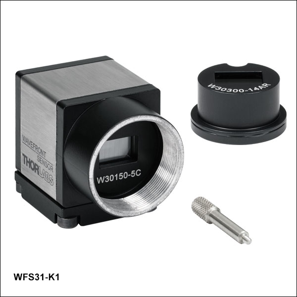 Zoom
Zoom- Includes General-Purpose Wavefront Sensor and an Additional 300 µm Pitch AR-Coated MLA
- MLAs Factory Calibrated for Use with the Included Hardware
- WFS31-K1(/M) Can Be Configured as:
- WFS31-5C(/M) by Installing the MLA with 150 µm Pitch and Chrome Mask
- WFS31-14AR(/M) by Installing the MLA with 300 µm Pitch and AR Coating
- WFS31-K2(/M) Can Be Configured as:
- WFS31-7AR(/M) by Installing the MLA with 150 µm Pitch and AR Coating
- WFS31-14AR(/M) by Installing the MLA with 300 µm Pitch and AR Coating
- Each Kit Includes a Pickup Tool Used to Easily Exchange the Installed MLA
These wavefront sensor kits come with all of the same specifications and hardware as the WFS31-5C(/M) and WFS31-7AR(/M) sold above, but they include another factory-calibrated 300 µm pitch, AR-Coated microlens array. A pickup tool is included to facilitate the easy exchange of these arrays in their patented, precision magnetic holders. Information about these wavefront sensors in the Specs and Selection Guide tabs above are given by the Item # of the configuration, rather than the Item # of the kit. For example, Item # WFS31-14AR should be referenced for the case of the 300 µm pitch MLA installed on a WFS31-K1. If a MLA has not been factory-calibrated for use with a particular sensor head, it should not be used. Contact Tech Support to upgrade a WFS for use with additional MLAs.

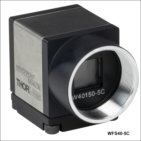 Zoom
ZoomClick to Enlarge
Frame rate and resolution (spot count) depend on the MLA, software-selectable active area, and operation mode.
- Square 11.26 mm x 11.26 mm Max Aperture
- 2048 x 2048 Pixel Max Camera Resolution
- One Mounted Microlens Array Included with Each WFS
- Chrome Mask or AR Coating
- 150 µm Pitch Arrays Have 73 x 73 Active Lenslets (Max)
- 300 µm Pitch Array Has 35 x 35 Active Lenslets (Max)
- User-Selectable Software Settings Control Frame Rate and Resolution
- Pupil Size Adjustment
- Operation in Normal or Faster Subsampling (sub2) Mode
- Software Controlled via Thorlabs' or User-Developed Application
Each of these Wavefront Sensors (WFS) is calibrated for use with the included mounted microlens array (MLA). A USB 3.0 interface to a PC running the software application is required to provide specified performance (see the Specs tab); however, these instruments can be operated with reduced performance via a USB 2.0 interface. Each WFS includes a bottom-mounted adapter plate with an 8-32 (M4) and a 1/4"-20 (M6) tap for mounting the sensor head on Ø1/2" posts.
Kits, available below, include two MLAs calibrated for the sensor head. If a MLA has not been factory-calibrated for use with a particular sensor head, it should not be used. Contact Tech Support to upgrade a WFS for use with additional MLAs.
| Large-Aperture Wavefront Sensorsa | |||
|---|---|---|---|
| Item # | |||
| Wavelength Range | 300 - 1100 nm | 400 - 900 nm | |
| Effective Focal Length | 4.1 mm | 5.2 mm | 14.6 mm |
| Lenslet Array Coating | Chrome Mask | AR Coated | |
| Lenslet Pitch | 150 µm | 300 µm | |
| Wavefront Accuracy (at 633 nm) | λ/25 rms | λ/30 rms | λ/40 rms |
| Wavefront Sensitivity (at 633 nm) | λ/80 rms | λ/100 rms | λ/120 rms |
| Frame Rate | 8 - 98 fps | 10 - 98 fps | |
| Camera Resolution | 2048 x 2048 Pixels Max, Software Selectable | ||
| High-Speed Control Box with PoCL and Table Clamps |
- | ||
| Included Cable | USB 3.0 Type-A to Mini-B Cable, 3 m | ||

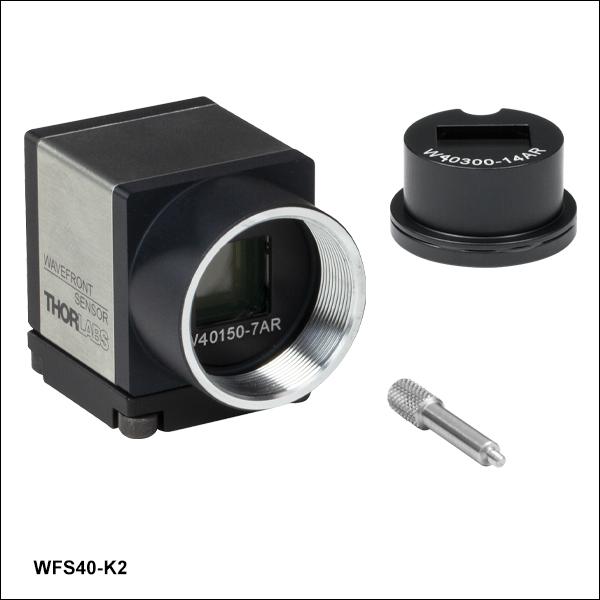 Zoom
Zoom- Includes Large-Aperture Wavefront Sensor and an Additional 300 µm Pitch AR-Coated MLA
- MLAs Factory Calibrated for Use with the Included Hardware
- WFS40-K1(/M) Can Be Configured as:
- WFS40-5C(/M) by Installing the MLA with 150 µm Pitch and Chrome Mask
- WFS40-14AR(/M) by Installing the MLA with 300 µm Pitch and AR Coating
- WFS40-K2(/M) Can Be Configured as:
- WFS40-7AR(/M) by Installing the MLA with 150 µm Pitch and AR Coating
- WFS40-14AR(/M) by Installing the MLA with 300 µm Pitch and AR Coating
- Each Kit Includes a Pickup Tool Used to Easily Exchange the Installed MLA
These wavefront sensor kits come with all of the same specifications and hardware as the WFS40-5C(/M) and WFS40-7AR(/M) sold above, but they include another factory-calibrated 300 µm pitch, AR-Coated microlens array and a tool to facilitate the easy exchange of these arrays in their patented, precision magnetic holders. Information about these wavefront sensors in the Specs and Selection Guide tabs above are given by the Item # of the configuration, rather than the Item # of the kit. For example, Item # WFS40-14AR should be referenced for the case of the 300 µm pitch MLA installed on a WFS40-K1. If a MLA has not been factory-calibrated for use with a particular sensor head, it should not be used. Contact Tech Support to upgrade a WFS for use with additional MLAs.

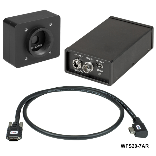 Zoom
ZoomClick to Enlarge
Frame rate and resolution depend on the MLA, software-selectable active area, and operation mode.
- Rectangular 7.20 x 5.40 mm Max Aperture
- 1440 x 1080 Pixel Max Camera Resolution
- One Mounted Microlens Array Included with Each WFS
- Chrome Mask or AR Coating
- 150 µm Pitch Arrays Have 47 x 35 Active Lenslets (Max)
- 300 µm Pitch Array Has 23 x 17 Active Lenslets (Max)
- User-Selectable Software Settings Control Frame Rate and Resolution
- Pupil Size Adjustment
- Operation in Normal, 2x2 Binning (Bin 2), or High-Speed Mode
- Software Controlled via Thorlabs' or User-Developed Application
These WFS include a separate control box that connects to the sensor head with the included cable. During high-speed mode operation, the field-programmable gate array (FPGA) built into the control box processes the image data and sends only the calculated spot centroid coordinates to the PC. In contrast, the entire image is sent to the PC when the WFS operates in normal and Bin 2 modes. A USB 2.0 interface to a PC running the software application is required for operation. Each WFS has three 8-32 (M4) taps on the bottom of the housing for mounting on Ø1/2" posts and four 4-40 taps on the front face for compatibility with Thorlabs' 30 mm Cage Systems.
Kits, available below, include two MLAs calibrated for the sensor head. If a MLA has not been factory-calibrated for use with a particular sensor head, it should not be used. Contact Tech Support to upgrade a WFS for use with additional MLAs.
| High-Speed Wavefront Sensorsa | |||
|---|---|---|---|
| Item # | |||
| Wavelength Range | 300 - 1100 nm | 400 - 900 nm | |
| Effective Focal Length | 4.1 mm | 5.2 mm | 14.6 mm |
| Lenslet Array Coating | Chrome Mask | AR Coated | |
| Lenslet Pitch | 150 µm | 300 µm | |
| Wavefront Accuracy (at 633 nm) | λ/30 rms | λ/60 rms | |
| Wavefront Sensitivity (at 633 nm) | λ/100 rms | λ/200 rms | |
| Frame Rate | 23 - 880 fps | 28 - 1120 fps | |
| Camera Resolution | 1440 x 1080 Pixels Max, Software Selectable | ||
| High-Speed Control Box with PoCL and Table Clamps |
 |
||
| Included Cable | USB 2.0 Type-A to Mini-B Cable, 2 m | ||

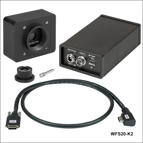 Zoom
Zoom- Includes a High-Speed Wavefront Sensor, an Additional 300 µm Pitch AR-Coated MLA, and Control Box
- MLAs Factory Calibrated for Use with the Included Hardware
- WFS20-K1(/M) Can Be Configured as:
- WFS20-5C(/M) by Installing the MLA with 150 µm Pitch and Chrome Mask
- WFS20-14AR(/M) by Installing the MLA with 300 µm Pitch and AR Coating
- WFS20-K2(/M) Can Be Configured as:
- WFS20-7AR(/M) by Installing the MLA with 150 µm Pitch and AR Coating
- WFS20-14AR(/M) by Installing the MLA with 300 µm Pitch and AR Coating
- Each Kit Includes a Pickup Tool Used to Easily Exchange the Installed MLA
These wavefront sensor kits come with all of the same specifications and hardware as the WFS20-5C(/M) and WFS20-7AR(/M) sold above, but they include another factory-calibrated 300 µm pitch, AR-Coated microlens array and a tool to facilitate the easy exchange of these arrays in their patented, precision magnetic holders. Information about these wavefront sensors in the Specs and Selection Guide tabs above are given by the Item # of the configuration, rather than the Item # of the kit. For example, Item # WFS20-14AR should be referenced for the case of the 300 µm pitch MLA installed on a WFS20-K1. If a MLA has not been factory-calibrated for use with a particular sensor head, it should not be used. Contact Tech Support to upgrade a WFS for use with additional MLAs.
The CAB-WFS20-T1 cable is designed to connect a user-supplied external trigger source to the High-Speed Shack-Hartmann Wavefront Sensors (Item # Prefix WFS20). The CAB-DCU-T3 cable provides the same functionality for the General-Purpose and Large-Aperture Shack-Hartmann Wavefront Sensors (Item # Prefix WFS31 and WFS40, respectively). For trigger input specifications, please see the Specs tab above.
| Item # | CAB-WFS20-T1 |  |
Pin | Assignment | |
|---|---|---|---|---|---|
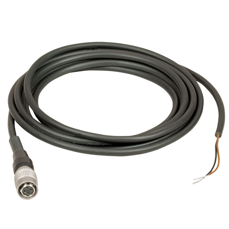 Click to Enlarge |
Connector Device Side | 4-Pin Hirose, Female | 1 | Not Used | |
| TTL Trigger Input | Bare Wire (Brown) | 2 | Trigger Input Ground (Black, Bare Wire) | ||
| Shielding | None | 3 | TTL Trigger Input (Brown, Bare Wire) | ||
| Length | 2 m | 4 | Not Used | ||
| Item # | CAB-DCU-T3 |  |
Pin | Assignment | |
|---|---|---|---|---|---|
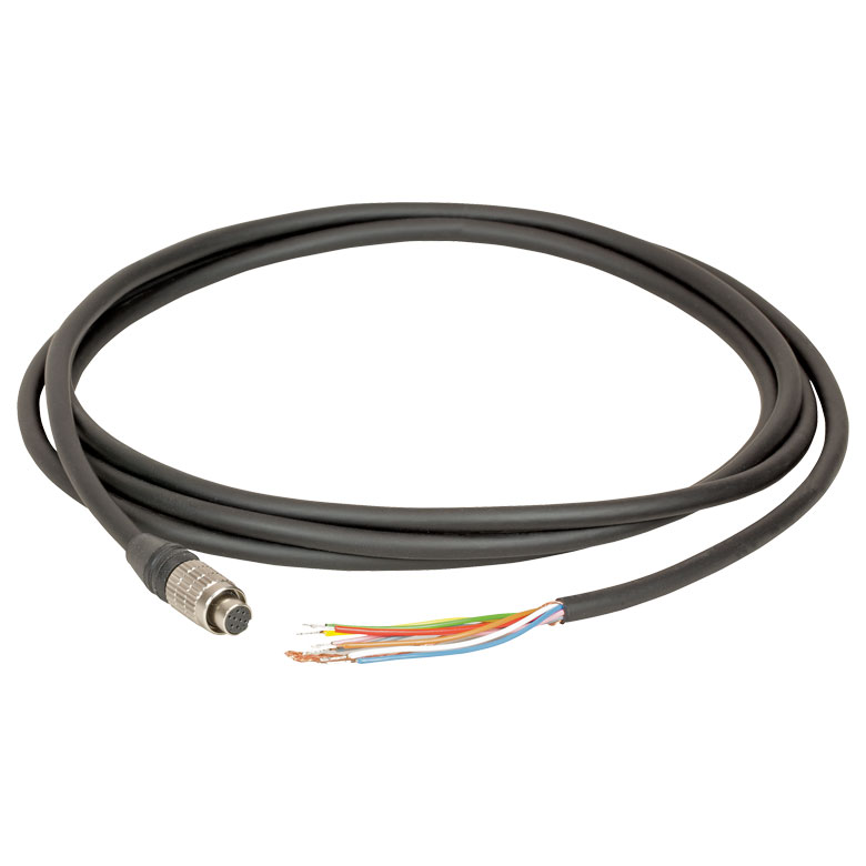 Click to Enlarge |
Connector Device Side | Hirose HR25-7TP-8S, Female | 1 | Ground (Gray) | |
| End Opposite Connectors | Tinned End of Wires | 2 | Flash Outputa - (Green) | ||
| Function | GPIO | 3 | GPIO 1, 3.3 V LVCMOS (Blue) | ||
| Trigger In (Bare Wire) | Yes | 4 | Trigger Inputa - (Brown) | ||
| Flash & Digital Out (Bare Wire) | Yes | 5 | Flash Outputa + (Yellow) | ||
| Cable Type | Shielded High-Flexible Control Cable 8 x 0.1 mm, Ø5.0 mm |
6 | GPIO 2, 3.3 V LVCMOS (Red) | ||
| Shielding | Single Shielded | 7 | Trigger Inputa + (White) | ||
| Length | 2 m | 8 | Output Supply Voltage, 5 V (100 mA) (Pink) | ||

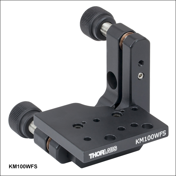 Zoom
Zoom
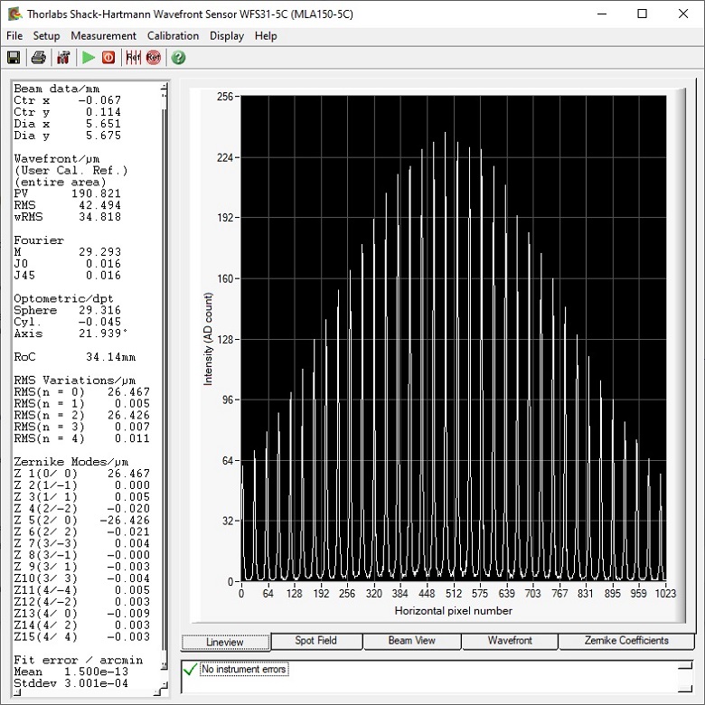
This animation shows how to convert between the right- and left-handed orientations for the KM100WFS. A similar process can be followed for the KM200PM(/M).
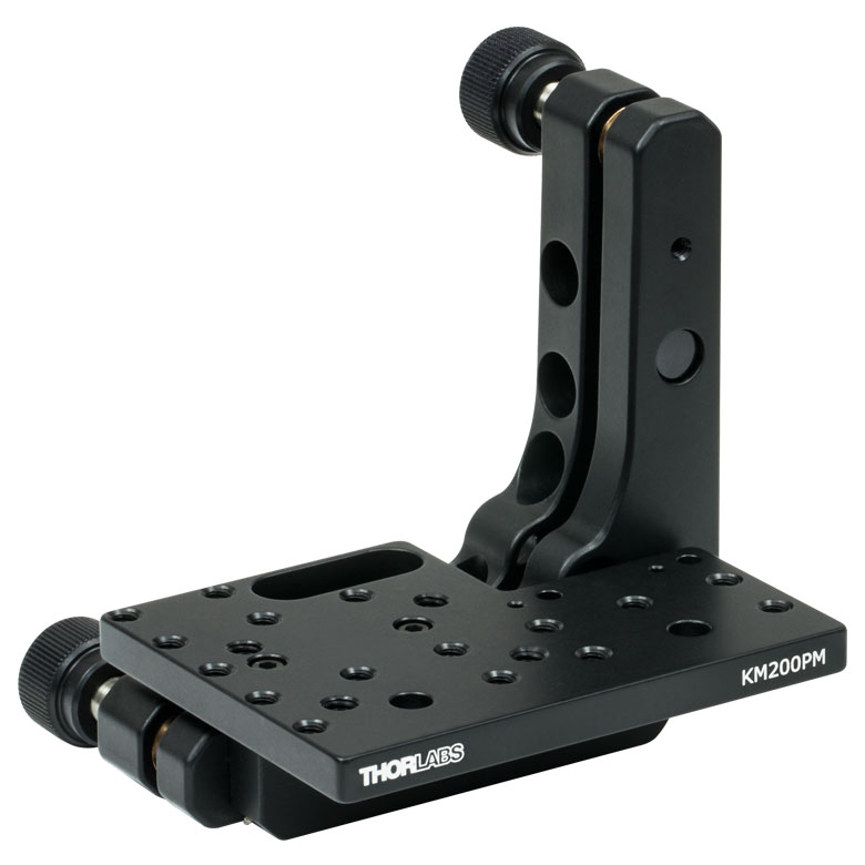
Click to Enlarge
The KM200PM mount platform's larger size allows for flexible mounting options.
| Platform Specifications | |||
|---|---|---|---|
| Item # | Tapped Holes | Through Holes | Platform Deptha |
| KM100WFS | - | #8 (x2) M3 (x3) |
1.52" (38.6 mm) |
| KM200PM | 6-32 (x16) 8-32 (x4) |
#8 (x2) | 2.10" (53.3 mm) |
| KM200PM/M | M4 (x21) | M4 (x2) | 53.3 mm (2.10") |
- Two 80 TPI Adjusters for ±4° of Fine Tip and Tilt Control
- 8 mrad Adjustment per Revolution
- Platform can be Removed and Secured to Either Arm Enabling Left- or Right-Handed Configuration
- Removable Knobs Expose Adjuster Screws with Hex Socket
Thorlabs' KM100WFS and KM200PM(/M) Kinematic Platform Mounts provide kinematic control for our CMOS-Based Shack-Hartmann Wavefront Sensors. Please note that the optical axis of the sensors will not be centered over the optical post. The animation to the right shows how to convert between the left- and right-handed orientations for the KM100WFS. This process is very similar for the KM200PM(/M).
The KM100WFS is designed to accommodate the WFS20 wavefront sensors, and features a similar design to our KM100PM platform. The WFS20 high-speed sensors can be mounted using the two #8 through holes near the front edge of the plate and the included 8-32 screws. The DCU CCD Cameras and the WFS20 sensors can also be mounted on the KM100WFS.
The KM200PM(/M) mount is larger than the KM100WFS, and can mount the WFS20 sensors using the two #8 (M4) through holes near the front edge of the plate. WFS30 and WFS40 can be mounted using one of the 8-32 tapped mounting holes. The larger profile and number of holes provides a variety of mounting options. The platform is secured to the front plate using two 4-40 screws with a 3/32" hex [the KM200PM/M uses M2.5 screws with a 2 mm (5/64") hex]. The two pieces of the mounting platform assembly are held together with two 3-48 screws [5/64" (2 mm) hex]. If desired, the mounting plate can also be removed and replaced with a user-supplied alternative, enabling custom mounting options.