 Products Home / Detectors / Amplified Detectors / InGaAs Amplified Photodetectors / InGaAs Avalanche Photodetectors
InGaAs Avalanche Photodetectors
- High-Speed Response up to 1.6 GHz
- Conversion Gains up to 9.0 × 10⁶ V/W
- Wavelength Ranges Covering 850 to 1700 nm
- Temperature-Compensated and Variable Gain Versions Available
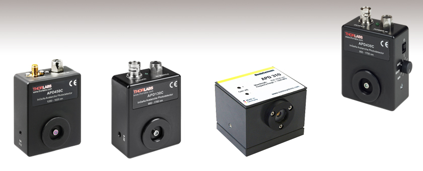
APD450C
High Speed, Temperature-
Compensated APD
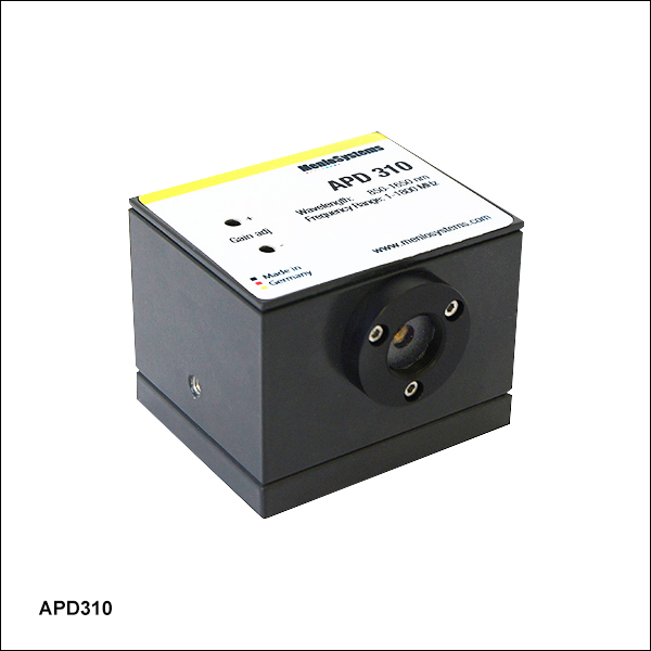
APD310
High-Speed APD
APD130C
Temperature-Compensated APD
APD430C
Variable-Gain,
Temperature-Compensated APD


Please Wait
| InGaAs APD Selection Guide | |||
|---|---|---|---|
| Item # | Wavelength Range |
Bandwidth (3 dB) |
Type (Quick Links) |
| APD130C(/M) | 900 - 1700 nm | DC - 50 MHz | Temperature Compensated |
| APD410C(/M) | DC - 10 MHz | Variable Gain, Temperature Compensated |
|
| APD430C(/M) | DC - 400 MHz | ||
| APD450C | 1260 - 1620 nm | 0.3 - 1600 MHz | |
| APD310 | 850 - 1650 nm | 5 - 1000 MHz | Variable Gain, Temperature Compensated, High Speed |
Features
- Noise Equivalent Powers (NEP) as Low as 0.12 pW/√Hz
- Max Bandwidth up to 1.6 GHz at 3 dB
- Temperature-Compensated Versions Provide M Factor Stability of ≤±3% Over 18 to 28 °C
- Variable Gain Detectors Available: M Factor from 4 to 20 or 2 to 10
- Internal SM05 and External SM1 Threading for Lens Tubes
- Power Supply Included
Thorlabs' InGaAs Avalanche photodetectors (APDs) are designed to offer increased sensitivity and lower noise compared to standard PIN detectors, making them ideal for applications with low optical power levels. In addition to our standard APDs, versions featuring variable gain (i.e., M factor) and/or temperature compensation are offered.
In general, avalanche photodiodes use an internal gain mechanism to increase sensitivity. A high reverse bias voltage is applied to the diodes to create a strong electric field. When an incident photon generates an electron-hole pair, the electric field accelerates the electrons, leading to the production of secondary electrons by impact ionization. The resulting electron avalanche can produce a gain factor of several hundred times, described by a multiplication factor, M, that is a function of both the reverse bias voltage and temperature. In general, the M factor increases with lower temperatures and decreases with higher temperatures. Similarly, the M factor will increase when the reverse bias voltage is raised and decrease when the reverse bias voltage is lowered.
Our APD130C(/M) temperature-compensated APD features an integrated thermistor that adjusts the bias voltage to compensate for the effect of temperature changes on the M factor. In addition to being temperature compensated, the APD410C(/M), APD430C(/M), and APD450C variable-gain APDs allow the reverse bias voltage across the diode to be adjusted via a rotary knob on the side of the housing, which varies the M factor continuously from 4 to 20.
For extremely light-sensitive applications, Thorlabs offers Menlo Systems' APD310 variable-gain, high-sensitivity avalanche photodectector, which offers high-speed response up to 1 GHz.
A complete list of all of our APDs, including those that have a silicon photodiode for use at UV and visible wavelengths, can be found on the Selection Guide tab. Please note that these packaged APDs are not suitable for use as single photon counters. Thorlabs has single photon counters available here.
| Item # | APD130C(/M) | APD410C(/M) | APD430C(/M) | APD450C |
|---|---|---|---|---|
| Detector Type | InGaAs APD | |||
| Wavelength Range | 900 - 1700 nm | 1260 - 1620 nm | ||
| Output Bandwidth (3 dB) | DC - 50 MHz | DC - 10 MHz | DC - 400 MHz | 0.3 - 1600 MHz |
| Active Area Diameter | 0.2 mm | 75 µm with Ø1.5 mm Ball Lens | ||
| Typical Max Responsivity | 9 A/W @ 1500 nm (M = 10)a | 18 A/W @ 1550 nm (M = 20) | 9 A/W @ 1550 nm (M = 10) | |
| M Factorb | 10 | 4 - 20 (Continuously Adjustable) | 2 - 10 (Continuously Adjustable) | |
| M Factor Temperature Stabilityc | ±2% (Typical); ±3% (Max) | |||
| Transimpedance Gain | 50 kV/A (50 Ω Termination)d 100 kV/A (High-Z Termination) |
250 kV/A (50 Ω Termination)d 500 kV/A (High-Z Termination) |
5 kV/A (50 Ω Termination)d 10 kV/A (High-Z Termination) |
5 kV/A (50 Ω Termination) |
| Max Conversion Gaine,f | 0.9 × 10⁶ V/W | 9.0 × 10⁶ V/W | 1.8 × 10⁵ V/W | 45 × 103 V/W |
| CW Saturation Power | 4.2 µW | 0.45 µW @ 1550 nm (M = 20) 2.25 µW @ 1550 nm (M = 4) |
22 µW @ 1550 nm (M = 20) 110 µW @ 1550 nm (M = 4) |
0.1 mW @ 1550 nm (M=10) 0.5 mW @ 1550 nm (M=2) |
| Max Input Powerg | 1 mW | |||
| Minimum NEPh | 0.46 pW/√Hz (DC - 50 MHz) | 0.12 pW/√Hz (DC - 10 MHz) | 0.45 pW/√Hz (DC - 100 MHz) | 1.1 pW/√Hz (0.3 - 1600 MHz) |
| Integrated Noisei | 3.3 nW (RMS, DC - 50 MHz) | 0.38 nW (RMS, DC - 10 MHz) | 17 nW (RMS, DC - 400 MHz) | 35 nW (0.3 - 1600 MHz) |
| Electrical Output | 50 Ω BNC | 50 Ω SMA | ||
| Max Output Voltage Swing | 1.8 V (50 Ω Termination) 3.6 V (High-Z Termination) |
2.0 V (50 Ω Termination) 4.1 V (High-Z Termination) |
2.0 V (50 Ω Termination) | |
| DC Offset Electrical Output | < ±15 mV | < ±25 mV | < ±3 mV | N/A |
| Included Power Supplyj | ±12 V @ 250 mA (100/120/230 VAC, 50 - 60 Hz, Switchable) | |||
| General | ||||
| Operating Temperature Range | 0 to 40 °C (Non-Condensing) | |||
| Storage Temperature Range | -40 to 70 °C | |||
| Dimensions (H x W x D) | 2.97" x 2.00" x 1.08" (75.5 mm x 50.8 mm x 27.4 mm) |
2.97" x 2.20" x 1.09" (75.5 mm x 55.8 mm x 27.6 mm) |
2.83" x 2.22" x 1.08" (72.0 mm x 56.3 mm x 27.4 mm) |
|
| Item # | APD310 |
|---|---|
| Detector Type | InGaAs APD |
| Optical Input | Free Spacea |
| Wavelength Range | 850 - 1650 nm |
| Damage Threshold | 10 mW |
| Active Area Diameter | 0.04 mm |
| Frequency Range | 1 MHz - 1800 MHz |
| 3 dB Bandwidth | 5 MHz - 1000 MHz |
| Rise Time | 500 ps |
| Conversion Gain (Max)b | 2.5 x 10⁴ V/W @ 1 GHz, 1500 nm |
| NEP (Calculated)c | 13.3 pW/√Hz |
| Dark State Noise Leveld | -80 dBm |
| M Factor | 30 |
| Typical Max Responsivity | 0.9 A/W @ 1550 nm |
| Output Impedance | 50 Ω |
| Output Connector | BNC |
| Output Coupling | AC |
| Current Consumption (Max) | 200 mA |
| Supply Voltage | +12 to +15 Ve |
| Operating Temperature | 10 to 40°C |
| Storage Temperature | -20 to +85 °C |
| Storage Humidity | 10% to 90% RH |
| Dimensions | 60 mm x 50 mm x 47.5 mm (2.36" x 1.97" x 1.87") |
Click to Enlarge
Pulse Response to a ≤250 fs Pulse Train at 1560 nm
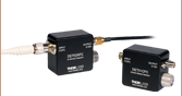
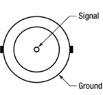
BNC Female Output (Photodetector)
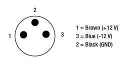
APD Male (Power Cables)
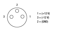
APD Female (Photodetector)
| Components for Fiber Coupling | |
|---|---|
| Item # | Description |
| - | Avalanche Photodetector |
| LM1XY(/M) | Translating Lens Mount for Ø1" Optics |
| SM1L10 | SM1 (1.035"-40) Lens Tube, 1" Long |
| - | Fiber Collimator (Dependent on Fiber) |
| AD11F or AD12F | SM1-Threaded Adapters for Ø11 or Ø12 mm Fiber Collimators (Dependent on Collimator) |
| - | Mounted Molded Aspheric Lens (Dependent on Collimator) |
| S1TM06, S1TM08, S1TM09, S1TM10, or S1TM12 |
SM1-Threaded Adapter for Molded Aspheric Lens Cell (Dependent on Lens) |
Click to Enlarge
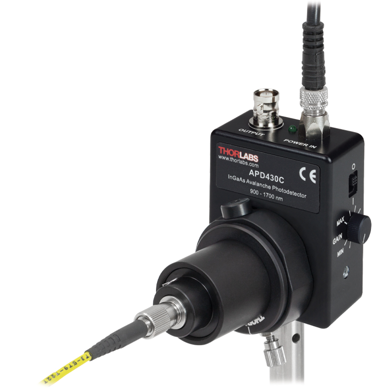
Output from a fiber is coupled into the photodetector using an aspheric lens to focus the signal onto the detector active area.
Fiber Coupling
In fiber coupling applications, we recommend taking into account the divergence of light from the fiber tip to ensure that all of the signal is focused onto the detector active area. When using a standard fiber connector adapter with a detector with an active area smaller than Ø1 mm, high coupling losses and degradation of the frequency response may occur.
To achieve high coupling efficiency, a fiber collimation package, focusing lens, and X-Y translator should be used, as shown in the photo to the right. The avalanche photodetector is shown with a fiber collimator, lens tube collimator adapter, lens tube, and X-Y translation mount. An adapter inside the lens tube holds an aspheric lens (not visible) to focus the collimated light onto the active area of the detector. The X-Y translation mount corrects for any centering issues.
Pulsed Laser Emission: Power and Energy Calculations

Determining whether emission from a pulsed laser is compatible with a device or application can require referencing parameters that are not supplied by the laser's manufacturer. When this is the case, the necessary parameters can typically be calculated from the available information. Calculating peak pulse power, average power, pulse energy, and related parameters can be necessary to achieve desired outcomes including:
- Protecting biological samples from harm.
- Measuring the pulsed laser emission without damaging photodetectors and other sensors.
- Exciting fluorescence and non-linear effects in materials.
Pulsed laser radiation parameters are illustrated in Figure 1 and described in the table. For quick reference, a list of equations are provided below. The document available for download provides this information, as well as an introduction to pulsed laser emission, an overview of relationships among the different parameters, and guidance for applying the calculations.
|
Equations: |
||||
 |
and |  |
||
 |
||||
 |
||||
 |
||||
Peak power and average power calculated from each other: |
||||
 |
and |  |
||
| Peak power calculated from average power and duty cycle*: | ||||
 |
*Duty cycle ( ) is the fraction of time during which there is laser pulse emission. ) is the fraction of time during which there is laser pulse emission. |
|||
Click to Enlarge
Figure 1: Parameters used to describe pulsed laser emission are indicated in the plot (above) and described in the table (below). Pulse energy (E) is the shaded area under the pulse curve. Pulse energy is, equivalently, the area of the diagonally hashed region.
| Parameter | Symbol | Units | Description | ||
|---|---|---|---|---|---|
| Pulse Energy | E | Joules [J] | A measure of one pulse's total emission, which is the only light emitted by the laser over the entire period. The pulse energy equals the shaded area, which is equivalent to the area covered by diagonal hash marks. | ||
| Period | Δt | Seconds [s] | The amount of time between the start of one pulse and the start of the next. | ||
| Average Power | Pavg | Watts [W] | The height on the optical power axis, if the energy emitted by the pulse were uniformly spread over the entire period. | ||
| Instantaneous Power | P | Watts [W] | The optical power at a single, specific point in time. | ||
| Peak Power | Ppeak | Watts [W] | The maximum instantaneous optical power output by the laser. | ||
| Pulse Width |  |
Seconds [s] | A measure of the time between the beginning and end of the pulse, typically based on the full width half maximum (FWHM) of the pulse shape. Also called pulse duration. | ||
| Repetition Rate | frep | Hertz [Hz] | The frequency with which pulses are emitted. Equal to the reciprocal of the period. | ||
Example Calculation:
Is it safe to use a detector with a specified maximum peak optical input power of 75 mW to measure the following pulsed laser emission?
- Average Power: 1 mW
- Repetition Rate: 85 MHz
- Pulse Width: 10 fs
The energy per pulse:

seems low, but the peak pulse power is:

It is not safe to use the detector to measure this pulsed laser emission, since the peak power of the pulses is >5 orders of magnitude higher than the detector's maximum peak optical input power.
| Posted Comments: | |
Om Suwal
(posted 2022-07-27 09:24:31.757) Dear sir,
I am looking a fast response ultra sensitive photodetector for CRDS setup. We will use Nd:YAG 1064 nm pulse laser for it. I am thinking to direct focus the signal coming out from one of the mirrors to the photodetector. Larger the active area is better for me. Would you please suggest me appropriate photodetector for it? Thank you! dpossin
(posted 2022-07-27 06:15:54.0) Dear Om,
Thank you for your feedback. I am reaching out to you directly in order to discuss the application with you. Juan Acosta
(posted 2021-10-20 10:26:29.31) Hi,
I would like to know if you can sell just the Housing of the detector without all the electronics just the empty box, with the screws and holes.
Thanks in Advance.
Best Regards
Juan Acosta soswald
(posted 2021-10-21 10:08:46.0) Dear Juan,
thank you for your feedback. I have reached out to you directly to discuss your application in more detail. Darrell Ramsey
(posted 2021-10-19 11:42:36.407) Can the detector be ordered windowless? soswald
(posted 2021-10-21 05:40:27.0) Dear Darrell,
thank you for your feedback. I have reached out to you directly to discuss your application in more detail to see if we can offer a suitable solution. Yaqing Zhang
(posted 2021-05-27 16:37:24.343) Hi,
I am very interested in APD410A and APD430A. From the manual, the typical detector responsivity curves of them only go up to 1000 nm, but I am wondering what they are at 1064 nm.
I really need these data values before I can place my order. Could you please send me the related data or graph? I am grateful for that.
Thanks very much! soswald
(posted 2021-05-31 10:08:53.0) Dear Yaqing,
thank you for your feedback. Unfortunately we have not measured the responsitivity at higher wavelengths than 1000 nm, so we cannot provide those data. soswald
(posted 2021-06-01 09:02:24.0) For 1064 nm sources we would recommend InGaAs instead of Si like in APD410C or APD430C. user
(posted 2018-07-11 11:30:33.107) Hello,
Is it possible to purchase the threaded fiber adapter of the APD310 separately? swick
(posted 2018-07-30 03:47:39.0) This is a response from Sebastian at Thorlabs. Thank you for the inquiry.
We can offer this adapter separately. Please contact techsupport@thorlabs.com for further information. tslim
(posted 2016-12-08 19:38:07.503) I want to use a fiber to couple light into APD410C/M.
I choose F220FC-1064 as the fiber collimator.
How do I choose a suitable aspheric lens? swick
(posted 2016-12-09 03:06:06.0) This is a response from Sebastian at Thorlabs. Thank you for the inquiry.
The lens should be chosen in consideration of optical parameters from your system like optical power, beam diameter and divergence.
In order to recommend a suitable lens for your setup, I have contacted you directly. user
(posted 2016-10-10 14:49:23.927) Regarding the APD430C, is the NEP specified for the gain M=4? If so, what is the NEP for M=20? This is not clear from the specs. swick
(posted 2016-10-11 05:58:49.0) This is a response from Sebastian at Thorlabs. Thank you for the inquiry.
The specified NEP for APD430C is valid for maximum gain (M=20). alekkom
(posted 2016-07-11 20:17:22.35) Hello! I want to measure very low level intensity of light at output of optical fiber. It's equal of 5-100 picowatts. The light is continuous. Wavelength ranges are 500-1000 and 1000-1700 nm. Would you like to offer the detectors for VIS and near IR ranges? shallwig
(posted 2016-07-12 10:52:22.0) This is a response from Stefan at Thorlabs. Thank you for your inquiry. At the moment we can offer silicon Avalanche photo detectors and InGaAs APDs but there are no APDs which cover the full range from 500-1700nm. I have contacted you directly to discuss your application in more detail. j.john.jelen
(posted 2016-02-12 10:07:26.74) I would like to be able to periodically calibrate this APD for use in our lab. Is there a way to do this? Without this, we cannot depend on the measurements.
thank you JJelen shallwig
(posted 2016-02-15 06:34:40.0) This is a response from Stefan at Thorlabs. Thank you very much for your inquiry. At the moment we cannot offer a calibration for amplified photo detectors. The monochromator we use for calibrating our power meter sensors has a diameter of 2mm, only detectors with active area >2mm and fixed gain stage can be offered calibrated. I will contact you directly to discuss your application in detail. user
(posted 2015-05-12 10:23:28.273) I am using APD110C. the problem I have is that the gain is reducing over time and the DC component is keep increasing. Is there a good way to control this? shallwig
(posted 2015-05-22 02:25:47.0) This is a response from Stefan at Thorlabs. Thank you very much for your inquiry, we do not understand the behavior of the APD as described. As you left no contact information could you please contact me at europe@thorlabs.com to troubleshoot this in more detail? Thank you. peupel
(posted 2015-01-30 15:23:31.92) Dear web team,
It would be nice having a direct link to the complete fiber coupling assembly (shown on the right side of product page) rather than several links to general product categories, or at least a list with suggested part number. This would help saving time to order the fiber coupling assembly.
Thanks - Jens shallwig
(posted 2015-01-30 11:51:05.0) This is a response from Stefan at Thorlabs. Thank you very much for your valuable feedback. Our web team will change the related items shown on the right side accordingly your suggestions.
I will contact you directly to check if there is anything else we can help you with. egregorio
(posted 2014-06-05 01:19:11.443) Dear Thorlabs,
I have an APD110C/M InGaAs Avalanche Photodetector. I want to use it for the mesurement of a 1534 nm pulsed laser with 3 mJ (peak pulse), 6 ns (pulse length) at 10 Hz. I need a neutral filter in order to avoid damage to the photodetector. In order to select it, could you indicate me what is the maximum optical input (damage threshold) for a 6ns pulse or similar. What is the saturation input for a 6ns pulse or similar? Thank you. tschalk
(posted 2014-06-06 04:37:05.0) This is a response from Stefan at Thorlabs. Thank you very much for your inquiry. We specify a maximum input power of 1mW for the APD110C. This value is the damage threshold for the photodiode, you can find this information in the spec sheet on our website here:
http://www.thorlabs.com/newgrouppage9.cfm?objectgroup_id=4047
With your pulse parameters this detector is not suitable. The bandwidth of the detector is from DC-50MHz so the repetition rate of your source (10Hz) is no problem. But, the detector would not work linearly for such short pulses (6ns) and the pulses cannot be properly time resolved. I will contact you directly to discuss your application in detail and which alternative detector might fit better. shikin
(posted 2014-05-30 09:18:44.32) Hi! How to use diode responsivity graph for correction of results? shallwig
(posted 2014-06-19 05:55:07.0) This is a response from Stefan at Thorlabs. Thank you very much for your inquiry. With the responsivity R(?) for a given wavelength you can estimate the OUTPUT voltage of the APD110C Avalanche Photodetector. The OUTPUT voltage is a function of incident light power POPT, detectors responsivity R(?),
multiplication factor M and transimpedance gain G given by:
Vout =POPT *R( ?)*M*G
The M-factor of APD110C is factory set to 10 at 23°C ambient temperature.
The amplifier’s transimpedance gain G is 100.000 V/A for all Models APD110C.
Further information can also be found in the manual on page 8 which you can find here: http://www.thorlabs.de/thorcat/19500/APD110C-Manual.pdf
I will contact you directly to discuss your application in detail. sys2643
(posted 2013-07-23 09:11:46.75) Hello
I bought the APD301 Photodetector from your web site.
But I have one problem when I had an experiment.
The problem is that the sensing area of APD301 is very small.
In our experiment, Now, we use 1520nm laser that has a bigger beam size than
the sensing area of APD301.
So, To solve this problem, I'm trying to find another product that can connect to
APD301 such as FPD310 or LENS Tube System.
So, Is it possible to use FPD310 system or lens tube system?
I'm not sure that it is possible to connect FPD310 or lens tube system to APD310.
If not, Do i use another optic system or product?
so if you know methods of products to reduce beam spot size or
increase the sensing size of detector using APD310.
please let me know the method or product.
thank you. cdaly
(posted 2013-07-25 10:45:00.0) Response from Chris at Thorlabs: Thank you for your feedback. The APD310 and PFD310 are each detectors in their own right. If your beam is a bit too large for the APD310 detector, I would suggest focusing it down with an optic, which can be mounted via the SM05 threading on the front. Focusing down to this 30um detector size should be much easier than coupling into the single mode fiber of the FPD310. weinberg.d.j
(posted 2013-03-27 11:10:20.347) Do you have any application notes on using APD110C or APD310 for time correlated single photon counting? My research group would like to look at NIR emission with a decay lifetime of approximately 2 microseconds, but I am not sure if the gain on these APDs will be sufficient. If necessary, we could use a boxcar integrator and collect the voltage output from the APD. tschalk
(posted 2013-04-19 05:16:00.0) This is a response from Thomas at Thorlabs. Thank you very much for your inquiry. Unfortunately we do not provide any application notes for our avalanche Photodetectors. Basically the APDs are not suited for single photon measurements, however we do offer single photon counters (http://www.thorlabs.com/newgrouppage9.cfm?objectgroup_id=5255). I will contact you directly to discuss your application and to find out if the detector is suitable for your needs. jvigroux
(posted 2012-10-04 13:20:00.0) A response from Julien at Thorlabs: Thank you for your inquiry. The rise time of this detector is about 10ns. natalie.haustrup
(posted 2012-10-04 07:44:41.0) Could you please tell me what the rise time of this detector is? jvigroux
(posted 2012-01-25 16:54:00.0) A response form Julien at Thorlabs: Thank you for your inquiry. The M factor can be assimilated to the gain of the detector. The higher the M factor, the higher the gain will be. The statement recommending not using a cell phone within less than 3 meters from the detector is based on a "worst case" scenario. The actual distance within which the power emitted by a mobile phone might be a problem will of course also depends on magnitude of your measurement signal. IF you have any furtehr question, please do not hesitate to contact us at techsupport@thorlabs.com user
(posted 2012-01-24 21:11:22.0) Hi, the APD manual says that different M-factors can be requested. What are the implications of a different M-factor (e.g. M=100) on the performance? Also, the manual states that mobile phones are not allowed within 3 meters (!) of the APD. Is this really required? Thank you. jvigroux
(posted 2011-12-12 07:20:00.0) A response form Julien at Thorlabs: The bandwidth of the APD110 series can be limited to 10kHz if required. I will contact you directly to discuss the details of your request. user
(posted 2011-12-09 13:20:09.0) A response from Tyler at Thorlabs: Thank you for sending us your custom request. I have contacted an application engineer who will work with our production engineers for the product line to see if we can offer a custom detector to meet your needs. alsturl
(posted 2011-12-08 15:35:06.0) I have a picosecond laser signal @5kHz which, after the photodetector, I digitize at 256kHz. Would it be possible to get a custom APD110A with a bandwidth of 10kHz so that the detector isn't faster than the digitizer? And without reducing the NEP or the output voltage into a Hi-Z? Your PDA100A is what I have been using, but I really could use more sensitivity. Thanks! -Adam jjurado
(posted 2011-03-15 18:10:00.0) Response from Javier at Thorlabs to Alex: Thank you for contacting us with your request. A couple of PDA series amplified photodiode detectors are most likely the best best fit for your application. A regular biased DET detector may not be sensitive enough. Also, the APD210/310 avalanche detectors are AC coupled, and, along with the APD110 series detectors, they have a low saturation power (in the order of a few microwatts). Below is a link for these detectors:
http://www.thorlabs.com/NewGroupPage9.cfm?ObjectGroup_ID=4
I will contact you directly to get a better assessment of your application. alekkom
(posted 2011-03-15 21:29:27.0) Hi!
I measure weak light signals of thin optical fiber (2-5 microns core diameter). Wavelengths are 300-1800 nm, light sources are deiterium or galogen lamps. Now I want to change my old detectors. What series of detectors (NON fiber-coupled!!!)are more appropriate for my field? DET, APD210(310) or APD 110 series....
Great thanks!
Alex |
Avalanche Photodetector Selection Guide
| Item # | Detector Type |
Wavelength Range |
3 dB Bandwidth | Active Area Diameter |
M Factor | Typical Max Responsivity |
Max Conversion Gaina |
Variable Gain |
Temperature Compensated |
|---|---|---|---|---|---|---|---|---|---|
| APD440A2 | UV Enhanced Silicon APD |
200 - 1000 nm | DC - 0.1 MHz | 1 mm | 5 - 50 | 25 A/W @ 600 nm (M = 50) | 1.25 x 10⁹ V/W | ||
| APD410A2 | DC - 10 MHz | 0.5 mm | 5 - 50 | 25 A/W @ 600 nm (M = 50) | 12.5 x 10⁶ V/W | ||||
| APD130A2 | DC - 50 MHz | 1 mm | 50 | 25 A/W @ 600 nm (M = 50) | 2.5 x 10⁶ V/W | - | |||
| APD430A2 | DC - 400 MHz | 0.2 mm | 10 - 100 | 50 A/W @ 600 nm (M = 100) | 5.0 x 10⁵ V/W | ||||
| APD410 | 5 - 900 MHzb | 0.2 mm | 50 | 22 A/W @ 650 nm (M = 50) | 4.5 x 10⁴ V/Wc | ||||
| APD440A | Silicon APD | 400 - 1000 nm | DC - 0.1 MHz | 1 mm | 10 - 100 | 53 A/W @ 800 nm (M = 100) | 2.65 x 10⁹ V/W | ||
| APD410A | DC - 10 MHz | 1.0 mm | 10 - 100 | 53 A/W @ 800 nm (M=100) | 26.5 x 10⁶ V/W | ||||
| APD130A | DC - 50 MHz | 1 mm | 50 | 25 A/W @ 800 nm (M = 50) | 2.5 x 10⁶ V/W | - | |||
| APD430A | DC - 400 MHz | 0.5 mm | 10 - 100 | 53 A/W @ 800 nm (M = 100) | 5.3 x 10⁵ V/W | ||||
| APD210 | 5 - 1000 MHzb | 0.5 mm | 100 | 50 A/W @ 800 nm (M = 100) | 2.5 x 10⁵ V/Wd | ||||
| APD130C | InGaAs APD | 900 - 1700 nm | DC - 50 MHz | 0.2 mm | 10 | 9 A/W @ 1500 nm (M = 10) | 0.9 x 10⁶ V/W | - | |
| APD410C | DC - 10 MHz | 0.2 mm | 4 - 20 | 18 A/W @ 1550 nm (M = 20) | 9.0 x 10⁶ V/W | ||||
| APD430C | DC - 400 MHz | 0.2 mm | 4 - 20 | 18 A/W @ 1550 nm (M = 20) | 1.8 x 10⁵ V/W | ||||
| APD450C | 1260 - 1620 nm | 0.3 - 1600 MHz | 1.5 mme | 2 - 10 | 9 A/W @ 1550 nm (M = 10) | 45 × 103 V/W | |||
| APD310 | 850 - 1650 nm | 5 - 1000 MHzb | 0.04 mm | 30 | 0.9 A/W @ 1550 nm (M = 30) | 2.5 x 10⁴ V/Wf |

 Zoom
Zoom| Key Specificationsa | |
|---|---|
| Item # | APD130C(/M) |
| Detector Type | InGaAs APD |
| Wavelength Range | 900 - 1700 nm |
| Output Bandwidth (3 dB) | DC - 50 MHz |
| Active Area Diameter | 0.2 mm |
| Typical Max Responsivity | 9 A/W @ 1500 nm (M = 10) |
| Transimpedance Gain | 50 kV/A (50 Ω Termination) 100 kV/A (High-Z Termination) |
| Max Conversion Gainb | 0.9 × 10⁶ V/W |
| M Factor | 10 |
| M Factor Temperature Stabilityc | ±2% (Typical); ±3% (Max) |
| Saturation Power (CW) | 4.2 µW |
| Minimum NEP (DC - 50 MHz)d | 0.46 pW/√Hz |
| Dimensions (W x H x D) | 2.97" x 2.00" x 1.08" |
- Temperature Compensated to Provide M Factor Stability of ≤±3% Over 18 to 28 °C
- Internal SM05 and External SM1 Threads Accept Fiber Adapters, Lens Tubes, and Other Components
- Power Supply Included
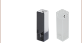
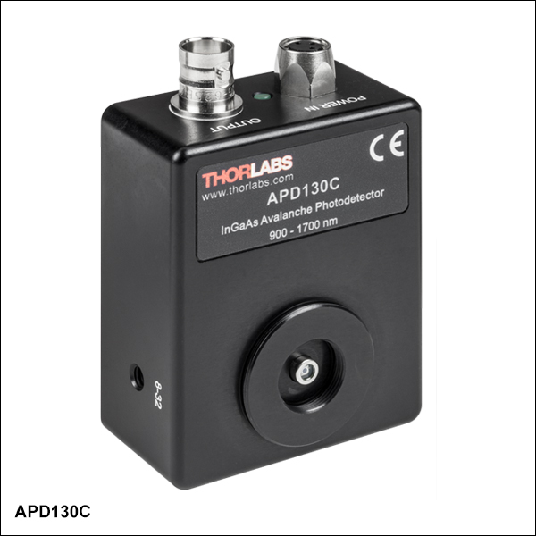
Thorlabs' APD130C(/M) Avalanche Photodetector features an integrated thermistor that maintains an M factor stability of ±3% or better over 23 ± 5 °C by adjusting the bias voltage across the avalanche photodiode, supplying improved output stability in environments with temperature variations.
The orientation of the mechanical and electrical connections, combined with the compact design, ensures that these detectors can fit into tight spaces. Three 8-32 (M4) mounting holes, one on each edge of the housing, further ensure easy integration into complicated mechanical setups. The housing also provides compatibility with both our SM05 and SM1 Lens Tubes. An internally SM1-threaded cap is included.
Fiber Coupling Note:
For fiber-coupled applications, we do not recommend using fiber connector adapters such as Thorlabs' S120-FC due to the small size of the detector. High coupling losses and degradation of the frequency response may occur. To achieve high coupling efficiency, a fiber collimation package, focusing lens, and X-Y translator should be used. See the Fiber Coupling tab for details.

 Zoom
Zoom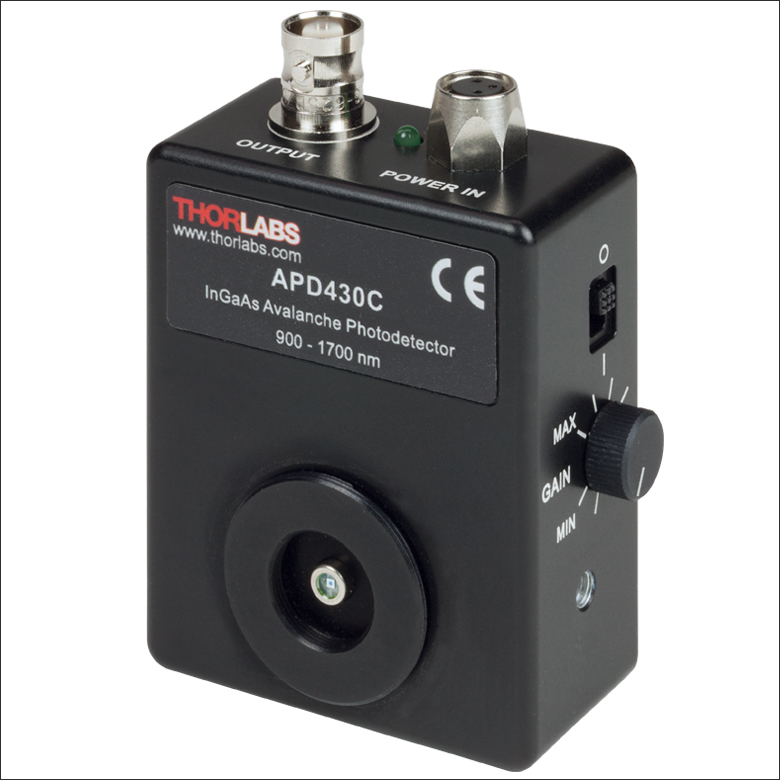
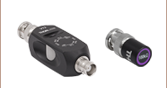
Click to Enlarge
The M Factor is controlled by a knob on the side of the APD.
- Continuously Variable Gain
- Temperature Compensated to Provide M Factor Stability of ±3% Over 18 to 28 °C
- Internal SM05 and External SM1 Threads Accept Fiber Adapters, Lens Tubes, and Other Components
- Power Supply Included
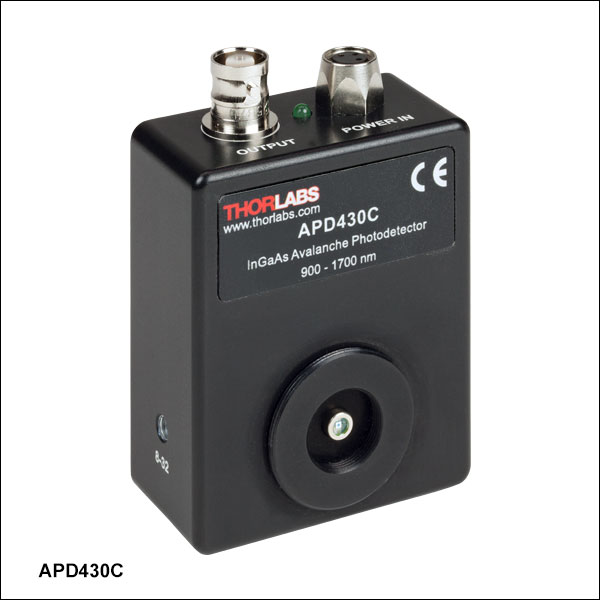
Thorlabs' APD410C(/M), APD430C(/M), and APD450C Avalanche Photodetectors have a variable gain that can be controlled by a knob on the right side of the housing. The gain knob adjusts the reverse bias voltage across the photodiode, allowing the M factor to vary. Like the APD130C detectors above, these devices feature an integrated thermistor that maintains an M factor stability of ±3% or better over 23 ± 5 °C by adjusting the bias voltage across the avalanche photodiode. These detectors offer different bandwidth ranges and sensitivity.
The orientation of the mechanical and electrical connections, combined with the compact design, ensures that these detectors can fit into tight spaces. Three 8-32 (M4) mounting holes, one on each edge of the APD410C(/M) and APD430C(/M) housing, further ensure easy integration into complicated mechanical setups. The APD450C detector offers universal 8-32/M4 mounting holes. The housing also provides compatibility with both our SM05 and SM1 Lens Tubes. An internally SM1-threaded cap is included.
Fiber Coupling Note:
For fiber-coupled applications, we do not recommend using fiber connector adapters such as Thorlabs' S120-FC with the APD410C or APD430C detectors due to the small size of the sensors. High coupling losses and degradation of the frequency response may occur. To achieve high coupling efficiency, a fiber collimation package, focusing lens, and X-Y translator should be used. See the Fiber Coupling tab for details.
| Key Specificationsa | |||
|---|---|---|---|
| Item # | APD410C(/M) | APD430C(/M) | APD450C |
| Detector Type | InGaAs APD | ||
| Wavelength Range | 900 - 1700 nm | 1260 - 1620 nm | |
| Output Bandwidth (3 dB)b | DC - 10 MHz | DC - 400 MHz | 0.3 - 1600 MHz |
| Active Area Diameter | 0.2 mm | 75 µm, with Ø1.5 mm Ball Lens | |
| Typical Max Responsivity | 18 A/W @ 1550 nm (M = 20) | 9 A/W @ 1550 nm (M = 10) | |
| Transimpedance Gain | 250 kV/A (50 Ω Termination) 500 kV/A (High-Z Termination) |
5 kV/A (50 Ω Termination) 10 kV/A (High-Z Termination) |
5 kV/A (50 Ω Termination) |
| Max Conversion Gainc | 9.0 × 10⁶ V/W | 1.8 × 10⁵ V/W | 4.5 × 10⁴ V/W (50 Ω Termination) |
| M Factor Adjustment Range | 4 - 20 (Continuous) | 2 - 10 (Continuous) | |
| M Factor Temperature Stabilityd | ±2% (Typical); ±3% (Max) | ||
| Saturation Power (CW) | 0.45 µW @ 1550 nm (M = 20) 2.25 µW @ 1550 nm (M = 4) |
22 µW @ 1550 nm (M = 20) 110 µW @ 1550 nm (M = 4) |
0.1 mW @ 1550 nm (M = 10) 0.5 mW @ 1550 nm (M = 2) |
| Minimum NEPe | 0.12 pW/√Hz (DC - 10 MHz) | 0.45 pW/√Hz (DC - 100 MHz) | 1.1 pW/√Hz (0.3 - 1600 MHz) |
| Dimensions (W x H x D) | 2.97" x 2.20" x 1.09" | 2.83" x 2.22" x 1.08" | |

 Zoom
Zoom| Key Specificationsa | |
|---|---|
| Item # | APD310 |
| Detector Type | InGaAs APD |
| Wavelength Range | 850 - 1650 nm |
| Frequency Range | 1 MHz - 1800 MHz |
| 3 dB Bandwidth | 5 MHz - 1000 MHz |
| Active Area Diameter | 0.04 mm |
| Responsivity Graph (Click to View) |
 |
| Conversion Gain (Max) | 2.5 × 10⁴ V/W @ 1 GHz, 1500 nm |
| NEP (Calculated)b | 13.3 pW/√Hz |
| M Factor | 30 |
| Typ. Max Responsivity | 0.9 A/W @ 1550 nm |
Applications
- Fast Laser Pulses
- Ultra-Low-Light Signals
- Temperature-Compensated Avalanche Photodiode
- Integrated Radio Frequency Amplifier
- Continuously Adjustable Gain Setting
- Long-Term Field Tested
- Free-Space Optical Input with Internal SM05 (0.535"-40) Threading
- Easy-to-Use Package
- Location-Specific (EU or US) Power Supply Included
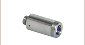
Originally developed for the detection of the beat note signal between CW or pulsed lasers, Menlo Systems' APD310 InGaAs Avalanche Photodetector is ideally suited for applications requiring very high sensitivity for low-light input signals in the 850 - 1650 nm range. The APD avalanche photodiode series can provide an extremely sensitive alternative to traditional PIN photodiodes. It is also fast enough for the characterization of, for example, pulsed solid-state lasers on the nanosecond time scale.
The detector maintains high gain stability over the 10 °C to 40 °C temperature range by utilizing a temperature compensation circuit, which adjusts the ~150 V DC bias to ensure operation near the breakdown voltage. The 3 dB bandwidth of the AC-coupled device is 5 - 1000 MHz.
Models for both the visible and near infrared range are available. The compact design of these detectors allows for easy OEM integration.
The units are especially recommended for applications such as metrology when homodyne or heterodyne optical beat signals of weak power have to be detected and amplified in a highly efficient way.

 Zoom
Zoom
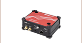
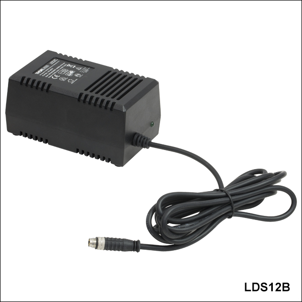
- Replacement Power Supply for Avalanche Photodetectors Sold Above (Except Item # APD310)
- ±12 VDC Power Output
- Current Limit Enabling Short Circuit and Overload Protection
- On/Off Switch with LED Indicator
- Switchable AC Input Voltage (100, 120, or 230 VAC)
- 2 m (6.6 ft) Cable with LUMBERG RSMV3 Male Connector
- UL and CE Compliant
The LDS12B ±12 VDC Regulated Linear Power Supply is intended as a replacement for the supply included with our APD series of avalanche photodetectors sold on this page, except for the APD310 photodetector. The cord has three pins: one for ground, one for +12 V, and one for -12 V (see diagram above). This power supply ships with a location-specific power cord. This power supply can also be used with the PDA series of amplified photodetectors, PDB series of balanced photodetectors, PMM series of photomultiplier modules, and the FSAC autocorrelator for femtosecond lasers.