Advanced Four-Channel LED Driver
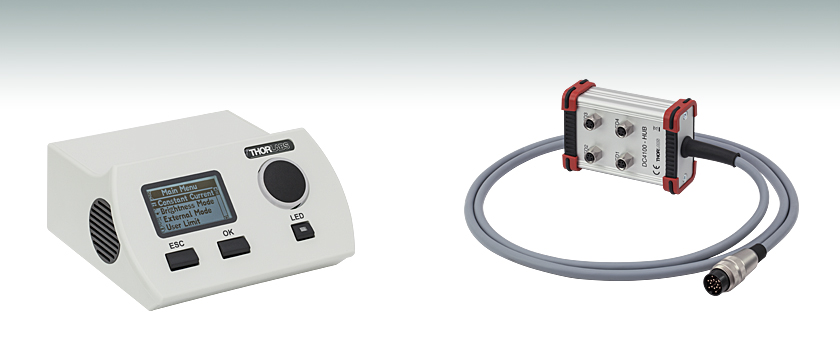
- Controls a Four-Wavelength LED4D Source or Four Individual LEDs
- LED Current Range: 0 to 1000 mA
- LED Current Accuracy: ±10 mA
- Modulation Frequency: 0 to 100 kHz
DC4100
4 Channel LED Driver
DC4100-HUB
Optional Hub for
Four Individual LEDs

Please Wait
| Key Specifications | ||
|---|---|---|
| Item # | DC4100 | DC4104 |
| LED Current Range | 0 - 1000 mA | |
| LED Current Resolution | 1 mA | |
| LED Current Accuracy | ±10 mA | |
| LED Forward Voltage | 5 V | |
| Modulation Frequency Range | 0 - 100 kHz, Sine Wave | |
| Modulation Voltage | 0 - 10 V | |
| Trigger Input Channels | 1 | 4 |
Applications
- Driver for Four Wavelength LED Source: LED4D Series
- Fluorescence Microscopy with Multi-Wavelength Requirements
Click for Details
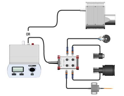
Multiple configuration options are available using the DC4100 or DC4104 LED Drivers.
Our 4-wavelength LED sources may be used directly with either the DC4100 or the DC4104, while our fiber-coupled, collimated, and heatsink-mounted LEDs require the use of a DC4100-HUB. Metal-core PCB LEDs are also compatible through the use of a DC4100-HUB and CAB-LEDD1 cables as pictured above.
Features
- Four Channels with Individual Current Adjustment
- Choose from Models with One (DC4100) or Four (DC4104) Separate Modulation Inputs
- Fast Switching Times of 1 ms Resolution Using the Modulation Input
- Linear Current Source Provides a Reliable and Reproducible Signal
- USB 2.0 Interface for Remote Control
- Compatible with µManager Automation Suite
- Customized Wavelength and Modulation Solutions Available
Thorlabs' DC4100 and DC4014 four-channel LED controllers are designed for microscopy and other applications that require multiple color channels. They are the ideal driver for the LED4D series four-wavelength LED sources. Via the optional DC4100-HUB, they can concurrently drive four LEDs like our collimated or uncollimated mounted LEDs (see diagram to the right). Using the DC4100-HUB connector hub and four CAB-LEDD1 connection cables, these drivers can also be used with four of our high-power LEDs on metal-core PCB ,or with four user-supplied LEDs. The LED current of each channel can be adjusted independently from 0 to 1000 mA or modulated via an external voltage; for details, see the Operating Modes section below.
These controllers offer a compact housing with a backlit, easy-to-read LCD display. They are operated via a wheel selector and three buttons on the front panel. Additionally, both LED drivers can be remotely operated via USB 2.0 by the software package, available for download in the Software tab, with an intuitive GUI and an extensive driver set. The LED drivers are also compatible with µManager, a versatile, open source, GUI software platform for automated microscopy. A plugin allows the user to control the LED drivers right out of the box.
Operating Modes
- Constant Current Mode: Each LED current is set to a separate, constant milliamp value. This mode is ideal for general-purpose applications.
- Brightness Mode: Each LED current is set to a separate value as a percentage of the maximum current. This mode is ideal for applications involving fluorescence microscopy.
- External Control Mode: The LED current is modulated through an external trigger from a signal generator (not included). For the DC4100 controller, all activated LEDs are controlled by the same modulation signal but can be individually deactivated. For the DC4104 controller, each LED is controlled by a separate modulation signal, all of which are provided through a single, included cable. Both controllers accept voltages ranging from 0 to 10 V, with 1 V corresponding to an LED current of 100 mA.
| LED Options | ||
|---|---|---|
 |
 |
 |
| Four-Wavelength LED Source |
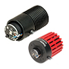
Fiber-Coupled LEDsa |
Collimated Microscope LEDsa |
 |
 |
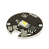 |
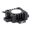
| Mounted LEDsa | Diffuse Backlight LEDa | PCB-Mounted LEDsb |
| LED Controller Selection Guide | |||||
|---|---|---|---|---|---|
| Type | Max Number of LEDs |
Max Current |
Modulation Mode |
USB | Compatible LEDs |
| upLED™ LED Driver |
1 | 1.2 A | - | Yes | Mounted Collimated Fiber Coupled Diffuse Backlight PCB Mounteda |
| Compact T-Cube™ Driver |
1 | 1.2 A | 0 - 5 kHz | No | |
| 4-Channel Driver | 4 | 1 A | 0 - 100 kHz | Yes | |
| Solis® LED Driver | 1 | 10 A | 0 - 1 kHz | No | High Power |
| High-Power Touchscreen Driver |
1 | 10.0 A | 0 - 250 kHz | Yes | High Power Mounted Collimated Fiber Coupled Diffuse Backlight PCB Mounteda |
| Item # | DC4100 | DC4104 |
|---|---|---|
| Constant Current Mode | ||
| LED Current Range | 0 - 1000 mA | |
| LED Current Resolution | 1 mA | |
| LED Current Accuracy | ±10 mA | |
| LED Forward Voltage | 5 V | |
| Brightness Mode | ||
| LED Current Range | 0 - 100% | |
| LED Current Resolution | 0.1 % (min. 1 mA) | |
| LED Current Accuracy | ±10 mA | |
| LED Forward Voltage | 5 V | |
| External Control Mode | ||
| Modulation Frequency Range | 0 - 100 kHz, Sine Wave | |
| Modulationa | Arbitrary | |
| Trigger Input Channels | 1 | 4 |
| Trigger Input (Maximum) | 10 V 1 V corresponds to 100 mA |
|
| General | ||
| Operating Temperature Rangeb | 0 to 40 °C | |
| Storage Temperature Range | -40 to 70 °C | |
| Dimensions (W x H x D) without Operating Elements | 160 mm x 80 mm x 150 mm | |
| Dimensions (W x H x D) with Operating Elements | 160 mm x 80 mm x 168 mm | |
| Warm Up Time for Rated Accuracy | <10 min | |
| Weight | <1 kg | |
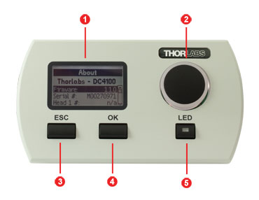
DC4100 Front Panel
| Callout | Connection | Callout | Connection |
|---|---|---|---|
| 1 | Display | 4 | OK Button |
| 2 | Display Control Knob | 5 | LED On/Off Button |
| 3 | Escape Button |
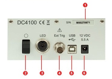
DC4100 Back Panel
| Callout | Connection | Callout | Connection |
|---|---|---|---|
| 1 | Serial Number of the Unit | 4 | External Trigger Input (BNC) |
| 2 | Power Switch | 5 | USB Connector |
| 3 | LED Connectora | 6 | Voltage Supply Connector |
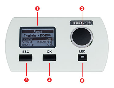
DC4104 Front Panel
| Callout | Connection | Callout | Connection |
|---|---|---|---|
| 1 | Display | 4 | OK Button |
| 2 | Display Control Knob | 5 | LED On/Off Button |
| 3 | Escape Button |
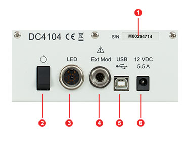
DC4104 Back Panel
| Callout | Connection | Callout | Connection |
|---|---|---|---|
| 1 | Serial Number of the Unit | 4 | External Trigger Input (8-Pin Push/Pull) |
| 2 | Power Switch | 5 | USB Connector |
| 3 | LED Connectora | 6 | Voltage Supply Connector |
Software for the DC4100 Series Advanced 4 Channel LED Driver
The available software is organized into the following categories:
- Software: Software and drivers package with graphical user interface for operating the device in standard applications. Package includes instrument drivers for the LabWindows™/CVI and LabVIEW™ National Instruments™ development environments.
- Firmware: The latest firmware version for the DC4100 and DC4104 LED Driver. For installation instructions consult the users manual
- Archive: Previous versions of the DC4100 and DC4104 software.
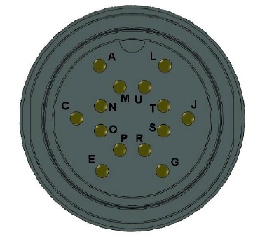
DC4100 and DC4104 LED Connection (14-Pin, M16 Female)
In the table below, LED 1, LED 2, LED 3, and LED 4 denote each LED included in the LED4D sources, ordered from shortest to longest wavelength.
| Pin | Description | Comment |
|---|---|---|
| A | LED 1 Anode | |
| C | LED 1 Cathode | |
| E | LED 2 Anode | |
| G | LED 3 Anode | |
| J | LED 3 Cathode | |
| L | LED 4 Anode | |
| M | LED 1 1 Wire EEPROM I/O | Do Not Use |
| N | DGNG | Do Not Use |
| O | LED 2 1 Wire EEPROM I/O | Do Not Use |
| P | LED 2 Cathode | |
| R | LED 3 1 Wire EEPROM I/O | Do Not Use |
| S | DGNG | Do Not Use |
| T | LED 4 1 Wire EEPROM I/O | Do Not Use |
| U | LED 4 Cathode |
DC4100 External Trigger
BNC Female
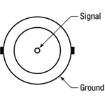
0 to 10 V, 0 to 100 kHz external LED control.
DC4104 External Trigger
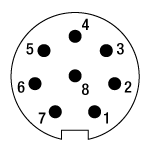 Male 8-Pin Push/Pull Connector |
Pin | Description | Bare Wire Color |
|---|---|---|---|
| 1 | LED Channel 1 | Pink | |
| 2 | GND | Green | |
| 3 | LED Channel 2 | Blue | |
| 4 | GND | Red | |
| 5 | LED Channel 4 | Brown | |
| 6 | GND | Yellow | |
| 7 | LED Channel 3 | Gray | |
| 8 | GND | White |
The picture above shows the male connector of the DC4104 external modulation cable. All ground wires share a common ground.
DC4100-HUB LED Connection
 Female M8x1 Connector |
Pin | Description |
|---|---|---|
| 1 | LED Anode | |
| 2 | LED Cathode | |
| 3 | EEPROM GND | |
| 4 | EEPROM IO |
The picture above shows the female connector of the DC4100-HUB. It is a standard M8x1 sensor circular connector. Pin 1 and 2 are the connection to the LED. Pin 3 and 4 are used for the internal EEPROM, please do not use these connections.
CAB-LEDD1 LED Connection
 Male M8x1 Connector |
Pin | Description | Wire Color |
|---|---|---|---|
| 1 | LED Anode | Brown | |
| 2 | LED Cathode | White | |
| 3 | EEPROM GND | Black | |
| 4 | EEPROM IO | Blue |
The picture above shows the male connector of the CAB-LEDD1. It is a standard M8x1 sensor circular connector. Pin 1 and 2 are the connection to the LED. Pin 3 and 4 are used for the internal EEPROM, please do not use these connections.
| Posted Comments: | |
user
(posted 2023-05-25 09:14:32.467) Hello. We want to use the PC app to control the LEDs. Windows recognizes the hardware and assigns a com port, but the app is not detecting anything. We tried reinstalling a few times, rebooting, and installing and older version. We have windows 10. Any clue whatt could cause this? hchow
(posted 2023-06-02 09:41:37.0) Dear User, thank you for your feedback. We are currently looking into this. I will contact you personally to offer technical support. Thank you. David Mayerich
(posted 2023-01-13 11:37:46.347) Is there any way to get C/C++ drivers for this? I have to control the LEDs using some existing controller software.
Thanks!
David wskopalik
(posted 2023-01-16 04:42:39.0) Thank you very much for your feedback!
The driver files are included in the software installation package which you can download in the “Software” tab. The package includes all the necessary DLL and header files.
I will contact you directly to provide further information. Brian A
(posted 2021-09-08 10:40:39.943) We have a Thorlabs DC4100 four channel LED device.
I’m a software engineer interface with this device using C# .NET 4.8
I downloaded the driver and example code from here:
https://www.thorlabs.com/software_pages/viewsoftwarepage.cfm?code=DC4100
The download only included x86 (32 bit) support. I interface through the dll file called
Thorlabs.DC4100.Interop.dll
File version 1.3.04
Can you tell me where the x64 (64 bit) support is located?
Thanks.
B. wskopalik
(posted 2021-09-16 08:00:45.0) Thank you very much for your inquiry!
The 64-bit dll file for .NET can be found in this folder when the software package 2.2 from our website is installed:
C:\Program Files\IVI Foundation\VISA\VisaCom64\Primary Interop Assemblies Sven Schörnich
(posted 2021-04-15 10:19:16.37) Ich frage mich, welche Stromstärken/lasten der Eingang für den Externen Control mode aushält? Das Steuersignal kann bis zu 10V haben, aber wie sieht es mit dem Eingangswiderstand des DC4104 aus? Welche Ströme können hier fliessen, wenn ich einen Verstärker vorschalten muß um aus max. 1,4V Steuersignal auf die finalen 10V zu kommen? MKiess
(posted 2021-04-19 07:54:07.0) Dear Sven, thank you very much for your inquiry. You should only apply a voltage between 0 and 10V to the external trigger input. The current flows here depending on the applied voltage. It is therefore important to know that a voltage of 1V applied to the external trigger input corresponds to a current of 100mA at the LED output. Patrick Fumo
(posted 2020-08-03 11:24:24.44) To whom it may concern,
Is there anyway I can get a more detailed document that describes the TLDC4100_32.dll? I need to be able to control some LEDs from a custom application but the current DC4100 Manual does not give enough information to write the code for such an interface. Thank you.
Best Regards,
Patrick Fumo MKiess
(posted 2020-08-04 04:33:23.0) Dear Patrick, thank you very much for your inquiry. In the following folder, which is included in the software download, you can find a Programmer's Reference, in which all functions are explained in detail.
C:\Program Files\IVI Foundation\VISA\WINNT\Thorlabs DC4100 Series\Manual Ralph Savioli
(posted 2020-03-17 16:59:07.053) This question is for the DC2100, but if the DC4100 has the same spec then all the better:
What is the delay time from an external trigger to the LED drive output? At both turn-on and turn-off when running in External mode.
I'm doing some time critical measurements synchronized to a CMOS imager and need to know this parameter. The spec only give the Rise/fall time - which is slightly different. nreusch
(posted 2020-03-26 03:32:27.0) This is a response from Nicola at Thorlabs. Thank you very much for your feedback. The delay of an LED with respect to the external trigger input depends on several factors: The capacity of the LED itself, cord capacities as well as drive current and modulation frequency. While we cannot specify a specific value for neither DC2100 nor DC4100, I will contact you directly to send you some exemplary measurements. Khoa Nguyen
(posted 2020-02-17 14:09:53.887) Can you make more than 4 channel LEDs, such as a custom number of channels? dpossin
(posted 2020-02-19 06:02:56.0) Dear Customer,
Thank you for your feedback. Unnfortunately we can not increase the number of channels for our DC4100 LED controller but we recently released a 6 wavelength source. You can have a look here: https://www.thorlabs.com/newgrouppage9.cfm?objectgroup_id=13597. Gary Yellen
(posted 2019-07-10 17:07:34.763) I purchased this item together with my Bergamo laser scanning microscope. I have downloaded the GUI, but would really like to control this in coordination with my TSI Quantalux camera. It doesn't appear there is any native support for the LED controller in ThorimageLS.
Is there an SDK (or at least documentation on the USB command stream) that would allow me to control this device from MATLAB? dpossin
(posted 2019-07-17 09:12:34.0) Dear Gary,
Thank you for your feedback,
It is not possible to controll the DC4104 from the Thorcam software but the Quantalux as well as the DC4104 can be triggered externally. You can feed a TTL signal from an external source into the camera and the LED driver in order to synchronize them.
The SDK files and the corresponding API you can find in the corresponding folder "Scientific Camera Interfaces". a woehl
(posted 2019-07-02 12:23:58.37) Hi, We are have some troubles getting the DC4104 to work with uManager (Win10). We have installed the most recent version of the control software (v2.2), yet when we run the hardware configuration wizard in uManager we see ThorlabsDCxxxx (unavailable). Any ideas? Perhaps we need a previous driver version for the uManager device adapter? Many thanks for your help!!! MKiess
(posted 2019-07-04 10:45:17.0) This is a response from Michael at Thorlabs. Thank you very much for your inquiry! The DC4104 is compatible with Windows 10 and MicroManager. If the DC4104 LED drivers are installed correctly and are shown in the Windows device Manager, you can install the DC-LED-drivers in MicroManager. I will contact you directly for further assistance. tou-cheu.xiong
(posted 2017-12-01 19:20:11.23) Hi
we have purchased the controller DC4104 and we would like to plug a LED strip. Unfortunate the controlleur could not identify any LED. Could you please let me know if it is possible to connect a LED strip (only anode and cathode) to this controller?
Thank you swick
(posted 2017-12-05 03:50:54.0) This is a response from Sebastian at Thorlabs. Thank you for the inquiry. Compatibility to DC4104 depends on properties of the LED like forward voltage and electrical current. I have contacted you directly for assistance. user
(posted 2017-10-26 15:36:36.797) Hi,
Is there a way to program directly the DC4104? I couldn't find any API for thhis controller.
Of course there is the option to control the LEDs via the external trigger but I would like to be able to also change/select the channels (LEDs) that are under the external control. That's also because every time the device is switched off and on I have to manually re-select the active LED.
Thanks,
Daniel wskopalik
(posted 2017-10-27 07:28:31.0) This is a response from Wolfgang at Thorlabs. Thank you very much for your inquiry.
The DC4100 and DC4104 can be controlled using the driver files available in the tab "Software" of this website. These files include a documentation of the driver commands as well as some example codes.
Unfortunately, you didn't leave an email address but please feel free to contact me any time at europe@thorlabs.com. simon.walker
(posted 2017-08-11 17:54:37.943) I would like to use the DC4100 with some high speed cameras. The cameras will be running at about 4Khz, with 10% duty cycle (i.e. an exposure time of 25us). They produce a 5V ttl pulse output, which is high during the exposure and low (0V) at other times. Can this be used to sync the DC4100 so that the LEDs turn on during the exposure and are off at other times?
Thanks,
Simon nreusch
(posted 2017-08-17 06:13:12.0) This is a response from Nicola at Thorlabs. Thank you very much for your inquiry. The DC4100 is suitable for an external trigger input up to 10 V and a modulation frequency range of 0 to 100 kHz for sine wave modulation. So you could use a 5 V TTL pulse with 4 kHz repetition rate. Please note that 1 V of the trigger input signal will correspond to 100 mA, so 5 V equal 500 mA. In order to decide whether the DC4100 would really meet your requirements, I will also contact you directly to discuss your application in more detail. kkomar
(posted 2017-05-29 14:57:21.033) I'm planning to use DC4100 with one of the diodes: MNWHL4 or MWWHL4 to switch on one them for relatively short time (50 us to 500 us) but with extremely low frequency (0.2 to 0.01 Hz). If the modulation signal of such low duty cycle will be connected with the trigger input of the DC4100 what would be main limiting factor: LED or the driver? Where can I check the rising time of Thorlabs LEDs? swick
(posted 2017-06-01 03:42:42.0) This is a response from Sebastian at Thorlabs. Thank you for the inquiry.
The bandwidth of DC4100 is 0 - 100 kHz, small-signal, sine wave.
If modulating with a waveform other than sine wave, the functional bandwidth will be reduced. I will contact you directly to discuss your application in detail. l.volkers
(posted 2017-01-31 04:41:09.943) I've read the software manual and it's not clear to me, whether there is a possibility to use the DC4104 as a pacing device. And if so, which additional devices/cables/software would be best functioning in combination with this device?
Best regards,
Linda wskopalik
(posted 2017-02-01 03:55:05.0) This is a response from Wolfgang at Thorlabs. Thank you very much for your inquiry.
The DC4104 can be externally modulated up to 100 kHz with a sine wave signal. The current applied to the connected LEDs will be modulated corresponding to the applied signal.
I will contact you directly to discuss your requirements and to provide further assistance. sergio.sigala
(posted 2016-08-23 12:41:52.15) Hello, may I have the TARIC code (Tariff Number) for this product?
Thank you swick
(posted 2016-08-26 02:13:13.0) This is a response from Sebastian at Thorlabs. Thank you for the inquiry. We will contact you directly about Tariff codes. banhuat.khor
(posted 2016-06-23 02:40:05.613) There are few systems in production using DC4100, we are facing intermittence LED light off in one of the channel (i.e always channel 1).
We have swapped the DC4100, but the problem still remain the same.
For recovery, we have to power cycle the DC4100.
Does your site have any advice for this issue ? What could have caused this LED light off.
Thanks.
Best rgds;
Mr Khor. shallwig
(posted 2016-06-23 06:44:24.0) This is a response from Stefan at Thorlabs. Thank you for contacting us and please apologize the problems you face with your DC4100 units. I have contacted you directly for troubleshooting this in detail. alexandr.erofeew
(posted 2016-03-28 12:50:31.117) Hi,
We have thorlabs DC2100 and DC4104, the question is, where we can find externel mode cable for DC4104?
Can we use Pulse Width Modulation Mode on DC4104 (some programm patch or new firmware)
Best regards. shallwig
(posted 2016-03-29 10:10:09.0) This is a response from Stefan at Thorlabs. Thank you very much for your inquiry. Unfortunately from the hardware side a PWM mode cannot be implemented into the DC4100/DC4104 drivers. Modulation can only be done externally with the cable we ship with each unit. I will contact you directly to offer you a replacement cable. emazy
(posted 2015-03-02 15:15:03.22) Dear Sir,
I desire to know the stability of the current over 60 sec range ?
Thank a lot in advance tschalk
(posted 2015-03-05 10:29:58.0) This is a response from Thomas at Thorlabs. Thank you very much for your inquiry. We recommend a warm up time of about 10 minutes, and after that the unit reaches the highest stability. The accuracy of the driver is +/-10mA but the stability will be much better, however we do not have specific measurement results for that. I will contact you directly with more detailed information. p.donn
(posted 2014-12-03 09:35:38.0) Hello,
is there any matlab support given for this product?
Best regards shallwig
(posted 2014-12-03 04:15:01.0) This is a response from Stefan at Thorlabs. Thank you very much for your inquiry. At the moment there are no Matlab support documents available for this LED driver. We will contact you directly for discussing your request in detail. user
(posted 2013-09-27 10:51:25.103) Dear Sirs,
I would like to know the time resolution in the External Control Mode. And could we apply "sine waves" or any waves in the External Control Mode?
Thank you.
SunJ jvigroux
(posted 2013-09-27 08:03:00.0) A response from Julien at Thorlabs: The time resolution of the analog circuit used for the external voltage control is extremely low but the limiting factor for fast application is normally the rise time of the output stage driving the LEDs. This time is usually in the low µs range (the exact value varies from LED to LED). Any type of modulation (sine, square, triangle etc.) can be applied to this input provided of course that the driving signal is not faster than the above mentioned rise time. jlow
(posted 2012-11-13 09:00:00.0) Response from Jeremy at Thorlabs: You can modulate the brightness of 4 LEDs individually using the DC4104. The 8-pin cable is provided (with open wiring on one end). eozkan
(posted 2012-11-12 20:33:07.027) Hello,
I have a question about DC4104 driver. Can I modulate the brightness of each of 4 LED externally using this driver? Do you provide necessary cables? jvigroux
(posted 2011-07-06 11:26:00.0) A response form Julien at Thorlabs: Dear Niccolo, thank you for your feedback! We are about to release a new version of the DC4100 driver that allows its operation on 64bits system. I will contact you directly to send you the installer. This version should be online within the next couple of weeks. banterle
(posted 2011-07-05 03:03:12.0) Dear customer service, I was using the dc4100 (which is great) succesfully controlling it from labview untill some days ago. Then we swapped to a 64 version of labview and the libraries are not considered valid anymore, is there a 64bit version of the drivers. Best regards, Niccolo tor
(posted 2011-01-10 10:05:07.0) Response from Tor at Thorlabs to mjensen: We updated the software for the DC2100 and DC4100 in order to make it compatible with Win 7 and Win Vista for both 32- and 64-bit. I will send you the FTP link shortly for downloading. mjensen
(posted 2010-12-30 20:09:17.0) Is there a driver for Windows 7 64-bit, if so, how do I get it; if not, when will it be available ? klee
(posted 2009-07-30 18:22:35.0) Response from Ken at Thorlabs to srubin: Sorry for the confusion. The LED4C can be found by clicking on the first Related Products or on the links in the Overview section. srubin
(posted 2009-07-30 17:46:16.0) picture at the top of the page shows LED4C but it is not for sale on this page magreevy
(posted 2009-07-01 13:17:51.0) document.write();
Great Product! |

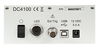
Click to Enlarge
DC4100 Rear Panel
- Allows Modulation of Four LEDs Together by One External Signal
- Constant Current and Brightness Modes Allow Current to be Set Individually for Each LED
- Designed for Use with the LED4D Series Light Sources
- Compatible with µManager Automation Suite
The DC4100 LED Driver is capable of driving the high-power LEDs in our four-wavelength LED sources simultaneously with a current range between 0 and 1000 mA. The current of each LED can be set individually or modulated together by one external signal through a rear-located BNC port (see photo to the right). The driver can also be used with up to four of our fiber-coupled, collimated, and uncollimated mounted LEDs via the DC4100-HUB connector hub, or our LEDs on metal-core PCB with the DC4100-HUB connector and the CAB-LEDD1 cable (both sold below).
This driver can be operated through a wheel selector and three buttons on the front panel or remotely via USB 2.0 and the included software package. For more information, please see the Overview tab and other tabs above.

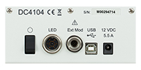
Click to Enlarge
DC4104 Rear Panel
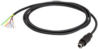
Click to Enlarge
Included External Modulation Cable
- Allows Individual Modulation of Four LEDs by Four External Signals Through a Single Cable
- Constant Current, Brightness, and External Control Modes Allow Current to be Set Individually for Each LED
- Designed for Use with the LED4D Series Light Sources
- Compatible with µManager Automation Suite
The DC4104 LED Driver is capable of driving the high-power LEDs in our four-wavelength LED sources simultaneously with a current range between 0 and 1000 mA. The current of each LED can be set individually by the driver or modulated individually by four external signals through the included cable shown in the photo above; please contact Tech Support for additional cables. The driver can also be used with up to four of our fiber-coupled, collimated, and uncollimated mounted LEDs via the DC4100-HUB connector hub, or our LEDs on metal-core PCB with the DC4100-HUB connector and the CAB-LEDD1 cable (both sold below). Please see the diagram in the section above for possible configurations.
This driver can be operated through a wheel selector and three buttons on the front panel or remotely via USB 2.0 and the included software package. For more information, please see the Overview tab and other tabs above.

 Female M8x1 Connector | Pin | Description |
|---|---|---|
| 1 | LED Anode | |
| 2 | LED Cathode | |
| 3 | EEPROM GND | |
| 4 | EEPROM IO |
- Allows User to Control Four Separate High-Brightness LEDs via the DC4100 or DC4104 Driver
- Designed for Use with Our Uncollimated or Collimated Mounted LEDs
The DC4100-HUB LED connector hub allows users to connect four individual high-brightness LEDs, such as our collimated or uncollimated mounted LEDs, to the DC4100 or DC4104 driver. Each LED is connected by a standard M8x1 sensor circular connector. The CAB-LEDD1 cable, sold below, allows an LED without the M8x1 connector to be used with the hub.

 Male M8x1 Connector |
Pin | Description | Wire Color |
|---|---|---|---|
| 1 | LED Anode | Brown | |
| 2 | LED Cathode | White | |
| 3 | EEPROM GND | Black | |
| 4 | EEPROM IO | Blue |
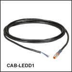
- 4-Pin M8 Connector on One Side
- 4 Bare Wires on Other Side
- 2 m Long, 24 AWG Wires
The 4-Pin M8 connection cable can be used to connect the high-power LEDs on metal core PCB or other custom LEDs to the following Thorlabs LED drivers: LEDD1B, DC2200, DC4100, and DC4104 (the latter two require the DC4100-HUB).
Pin Connection - Male
The diagram above shows the male connector for use with the above Thorlabs LED drivers. The connector is a standard M8x1 sensor circular connector. Pins 1 and 2 are the connection to the LED. Please note that the pin connection diagram shown here may not be valid for third-party LED drivers.
 Products Home



 Zoom
Zoom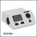

 4-Channel LED Driver