 Products Home / Optical Elements / Optical Mirrors / Dichroic Beamsplitters / Longpass Dichroic Mirrors/Beamsplitters
Longpass Dichroic Mirrors/Beamsplitters
- Cut-On Wavelengths from 425 nm to 1800 nm
- Round and Rectangular Versions Available From Stock
- Durable Hard Coatings
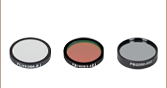
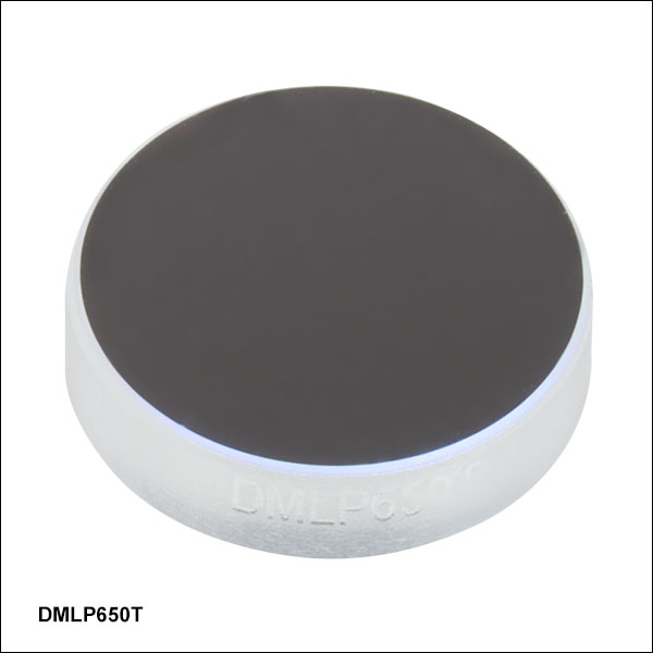
DMLP567L
Ø2"
DMLP950R
25 mm x 36 mm
DMLP638
Ø1"
DMLP1800T
Ø1/2"
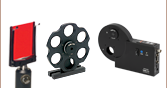
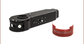
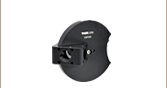
Application Idea
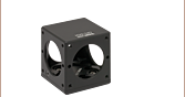
The CM1-DCH Dichroic Cage Cube Holding
a Rectangular Dichroic Mirror
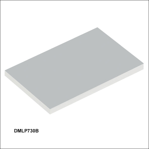
DMBP740B
35 mm x 52 mm


Please Wait
Longpass Dichroic Mirror Selection Guide
(Click Cut-On Wavelengths or Bands for Details)
| Dichroic Mirrors Selection Guide |
|---|
| Shortpass |
| Longpass |
| Multi-Band |
Features
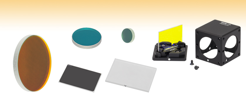
- Dichroic Filters Function as Longpass Filters with Minimal Absorption Losses
- Multi-Band Dichroic Filter with Two Transmission Bands and One Reflection Band
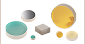
- Five Sizes Available: Ø1/2", Ø1", Ø2", 25 mm x 36 mm, or 35 mm x 52 mm
- Hard Coating Allows Easy Handling and Cleaning
- Resistant to Damage from UV Light and Chemicals
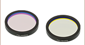
Thorlabs' Dichroic Mirrors/Beamsplitters spectrally separate light by transmitting and reflecting light as a function of wavelength. Longpass dichroic mirrors have a transmission and reflection band that are divided by a cut-on wavelength. This type of dichroic is highly reflective below the cut-on wavelength and highly transmissive above it. We also offer a multi-band dichroic mirror that can be used as a longpass mirror. This dichroic has two transmission bands and one reflection band that are separated by a cutoff and cut-on wavelength. It is highly transmissive below the cutoff wavelength and above the cut-on wavelength, while highly reflective between the cutoff and cut-on.
Our longpass dichroic mirrors are offered in several different cut-on wavelengths ranging from 425 to 1800 nm, which are listed in the selection guide graphic to the right. These mirrors are designed for use at a 45° angle of incidence and are available in five sizes: Ø1/2", Ø1", Ø2", 25 mm x 36 mm, and 35 mm x 52 mm. Please see below for transmission and reflection plots of each mirror.
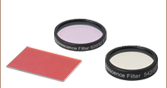
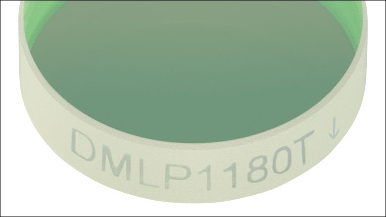
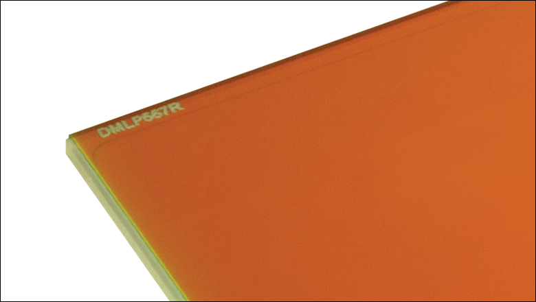
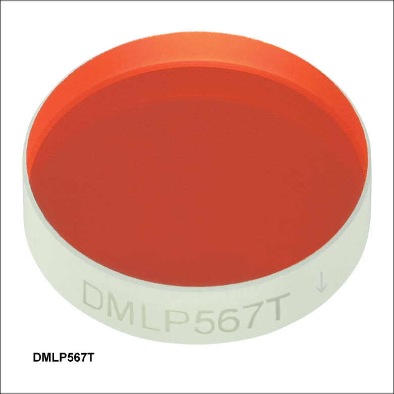
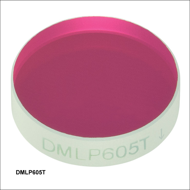
These optics feature a dichroic coating on one surface and an antireflection coating on the opposing surface. We recommend orienting the optic as illustrated in the diagram to the upper right. On round optics, an engraved arrow points toward the surface with the AR coating; on the 25 mm x 36 mm rectangular optics, the side with the engraving has the dichroic coating. The 35 mm x 52 mm dichroic mirrors feature a caret on the side that points towards the AR-coated surface.
For thermally sensitive applications, Thorlabs offers hot and cold mirrors. We also offer shortpass dichroic mirrors, which are highly reflective above the cutoff wavelength and highly transmissive below it.
Applications
As shown in the Applications tab, these optics can be used to combine a beam that has a wavelength (or wavelength range) shorter than the cut-on wavelength with a beam that has a wavelength (or wavelength range) longer than the cut-on wavelength. They are also commonly used to split spatially overlapping beams of different colors.
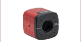
Longpass dichroic mirrors are commonly used in fluorescence microscopy. Excitation light is reflected by the dichroic mirror into the objective, and the emitted fluorescence (which has a longer wavelength than the excitation wavelength) is transmitted through the dichroic mirror into the scientific camera or photomultiplier tube (PMT). Residual excitation light that is back-reflected or scattered by the sample will be reflected a second time by the dichroic mirror, preventing it from reaching the camera or PMT and causing spurious signals.
Surface Quality and Durability
Thorlabs' Dichroic Mirrors/Beamsplitters consist of a hard, ion-beam-sputtered coating deposited on a UV fused silica substrate, providing excellent transparency over the operating wavelength range, virtually zero autofluorescence, and a low coefficient of thermal expansion, making them an ideal choice for applications from the UV to the near IR. The hard coatings themselves have a 40-20 scratch-dig surface quality and allow the optics to be cleaned and handled like typical glass. As opposed to soft coatings, they have improved resistance to humidity effects and can withstand high optical irradiation intensities with no noticeable degradation or burns, even under prolonged exposure to ultraviolet light. Please see the Damage Thresholds tab for detailed information on the damage thresholds of these filters.
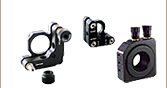
Mounting Options
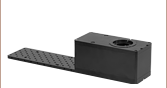
For customers who wish to use these dichroic mirrors/beamsplitters in microscopy applications, Thorlabs manufactures a family of filter cubes and mounts. The Cerna® Breadboard Top with Two-Position Slider can be used to mount the 35 mm x 52 mm dichroics for DIY microscopy. Additionally, the 25 mm x 36 mm rectangular dichroics can be mounted in the KM2536 Kinematic Mount.
Click to Enlarge
Round Versions: Engraved Arrow Denotes Side with AR Coating
(See Applications Tab for Details)


| General Specifications | |||||
|---|---|---|---|---|---|
| Size | Ø1/2" | Ø1" | Ø2" | 25.0 mm x 36.0 mm | 35.0 mm x 52.0 mm |
| Clear Aperture | ≥Ø11.43 mm | ≥Ø22.86 mm | ≥Ø45.72 mm | ≥22.5 mm x 32.4 mm | ≥85%, Elliptical |
| Thickness | 3.2 mm | 3.2 mm | 5.0 mm | 1.0 mm | 2.0 mm (DMLP730B Only) or 3.0 mm |
| Incident Angle | 45° | ||||
| Surface Quality | 40-20 Scratch-Dig | ||||
| Transmitted Wavefront Error | <λ/4 @ 633 nm Over Clear Aperture | ≤λ/4 @ 632.8 nm Over Clear Aperture | |||
| Substrate Material | UV Fused Silicaa | ||||
| Wavelength Specifications | |||||||||
|---|---|---|---|---|---|---|---|---|---|
| Item # Prefix | Cut-On Wavelength |
Transmission Band |
Absolute Transmission |
Average Transmission |
Reflection Band |
Absolute Reflectance |
Average Reflectance |
AR Coating Rangea |
Damage Threshold |
| DMLP425 | 425 nm | 440 - 800 nm | >85% | >90% | 380 - 410 nm | >90% | >95% | 400 - 800 nm | 1.50 J/cm2 (532 nm, 10 Hz, 10 ns, Ø250 µm) |
| DMLP490 | 490 nm | 505 - 800 nm | >85% | >90% | 380 - 475 nm | >90% | >95% | 400 - 800 nm | 1.00 J/cm2 (532 nm, 10 Hz, 10 ns, Ø538 µm) |
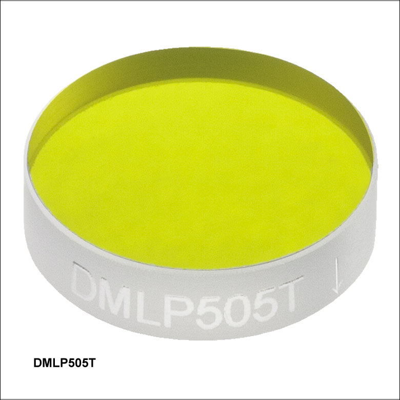
| DMLP505 | 505 nm | 520 - 800 nm | >85% | >90% | 380 - 490 nm | >90% | >95% | 400 - 800 nm | 1.50 J/cm2 (532 nm, 10 Hz, 10 ns, Ø250 µm) |
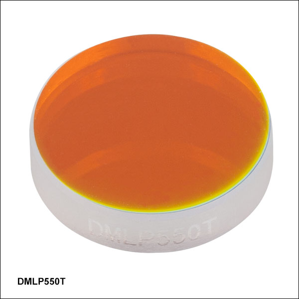
| DMLP550 | 550 nm | 565 - 800 nm | >85% | >90% | 380 - 533 nm | >90% | >95% | 400 - 800 nm | 0.50 J/cm2 (532 nm, 10 Hz, 10 ns, Ø538 µm) |
| DMLP567 | 567 nm | 584 - 800 nm | >85% | >90% | 380 - 550 nm | >90% | >95% | 400 - 800 nm | 1.50 J/cm2 (532 nm, 10 Hz, 10 ns, Ø250 µm) |
| DMLP605 | 605 nm | 620 - 800 nm | >85% | >90% | 470 - 590 nm | >90% | >95% | 400 - 800 nm | 1.50 J/cm2 (532 nm, 10 Hz, 10 ns, Ø250 µm) |
| DMLP638 | 638 nm | 655 - 700 nm | >85% | >90% | 580 - 621 nm | >90% | - | 400 - 800 nm | 1.50 J/cm2 (532 nm, 10 Hz, 10 ns, Ø250 µm) |
| DMLP650 | 650 nm | 685 - 1600 nm | >85% | >90% | 400 - 633 nm | >90% | >95% | 665 - 1600 nm | 0.25 J/cm2 (532 nm, 10 Hz, 10 ns, Ø538 µm) 2.00 J/cm2 (1064 nm, 10 Hz, 10 ns, Ø1.000 mm) |
| DMLP730 | 730 nm | 750 -1100 nm | - | >92% | 450 - 690 nm | - | >97% | 440 - 1800 nm | - |
| 1300 - 1400 nm, 1300 - 1800 nm, 1700 - 1800 nm |
- | >94% | |||||||
| DMLP735 | 735 nm | 750 - 1600 nm | - | >93% | 350 - 720 nm | - | >98% | 350 - 1600 nm | - |
| DMLP805 | 805 nm | 825 - 1300 nm | >85% | >90% | 400 - 785 nm | >90% | >95% | 823 - 1300 nm | - |
| DMLP900 | 900 nm | 932 - 1300 nm | >85% | >90% | 400 - 872 nm | >90% | - | 932 - 1700 nm | 1.00 J/cm2 (532 nm, 10 Hz, 10 ns, Ø250 µm) 6.50 J/cm2 (1064 nm, 10 Hz, 12 ns, Ø250 µm) |
| DMBP740b | 940 nm | 400 - 725 nm, 980 - 1700 nm |
- | >93% | 753 - 935 nm | - | >97% | 400 - 1700 nm | - |
| DMLP950 | 950 nm | 990 - 1600 nm | >85% | >90% | 420 - 900 nm | >90% | >95% | 932 - 1700 nm | 1.00 J/cm2 (532 nm, 10 Hz, 10 ns, Ø538 µm) 4.00 J/cm2 (1064 nm, 10 Hz, 10 ns, Ø1.000 mm) |
| DMLP1000 | 1000 nm | 1020 - 1550 nm | >85% | >90% | 520 - 985 nm | >90% | >95% | 1020 - 1550 nm | 0.25 J/cm2 (1064 nm, 10 Hz, 10 ns, Ø459 µm) |
| DMLP1150 | 1150 nm | 1200 - 1900 nm | - | >95% | 720 - 1100 nm | - | >95% | 400 - 1900 nm | - |
| DMLP1180 | 1180 nm | 1260 - 1700 nm | >85% | >90% | 750 - 1100 nm | >90% | >95% | 932 - 1700 nm | 5.00 J/cm2 (1064 nm, 10 Hz, 12 ns, Ø250 µm) |
| DMLP1500 | 1500 nm | 1550 - 2000 nm | >85% | >90% | 1000 - 1450 nm | >90% | >95% | 1550 - 2000 nm | - |
| DMLP1800 | 1800 nm | 1850 - 2100 nm | >85% | >90% | 1500 - 1750 nm | >90% | >95% | 1800 - 2100 nm | 5.00 J/cm2 (2050 nm, 62.5 Hz, 10 ns, Ø348 µm) |
Typical Applications for Dichroic Mirrors/Beamsplitters
- Fluorescence Microscopy
- Splitting or Combining Two Beams of Different Wavelengths
- Filtering of Spectral Components
Ray Diagram Illustration
Figure 1 depicts a dichroic mirror/beamsplitter being used to combine a transmitted beam (blue) with a reflected beam (red). The transmitted beam has a wavelength in the transmission band of the optic, and the reflected beam has a wavelength in the reflection band of the optic. If the direction of propagation is reversed, the optic becomes a beamsplitter, as shown in Figure 2.
In both cases, the combined, polychromatic beam is on the dichroic coated side of the dichroic filter. To better direct the reflection, we recommend orienting them such that the wavelength being reflected does not pass through the substrate. Dichroic mirrors/beamsplitters differ from typical beamsplitters in that the beams can be combined or separated without a significant loss of intensity.
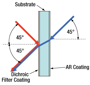
Figure 1. This figure depicts a dichroic mirror being used to combine two beams of different colors.
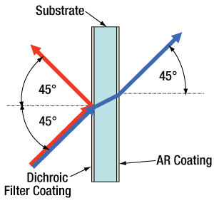
Figure 2. This figure depicts a dichroic mirror being used to split two beams of different colors.
Damage Threshold Data for Thorlabs' Dichroic Mirrors/Beamsplitters
The specifications below are measured data for Thorlabs' dichroic mirrors/beamsplitters. Damage threshold specifications are constant for a given coating type, regardless of the size of the mirror.
| Damage Threshold Specifications | |
|---|---|
| Coating Designation (Item # Prefix) |
Damage Threshold |
| DMLP900 | 1.00 J/cm2 (532 nm, 10 Hz, 10 ns, Ø250 µm) 6.50 J/cm2 (1064 nm, 10 Hz, 12 ns, Ø250 µm) |
| DMLP950 | 1.00 J/cm2 (532 nm, 10 Hz, 10 ns, Ø538 µm) 4.00 J/cm2 (1064 nm, 10 Hz, 10 ns, Ø1.000 mm) |
| DMLP1000 | 0.25 J/cm2 (1064 nm, 10 Hz, 10 ns, Ø459 µm) |
| DMLP1180 | 5.00 J/cm2 (1064 nm, 10 Hz, 12 ns, Ø250 µm) |
| DMLP1800 | 5.00 J/cm2 (2050 nm, 62.5 Hz, 10 ns, Ø348 µm) |
| Damage Threshold Specifications | |
|---|---|
| Coating Designation (Item # Prefix) |
Damage Threshold |
| DMLP425 | 1.50 J/cm2 (532 nm, 10 Hz, 10 ns, Ø250 µm) |
| DMLP490 | 1.00 J/cm2 (532 nm, 10 Hz, 10 ns, Ø538 µm) |
| DMLP505 | 1.50 J/cm2 (532 nm, 10 Hz, 10 ns, Ø250 µm) |
| DMLP550 | 0.50 J/cm2 (532 nm, 10 Hz, 10 ns, Ø538 µm) |
| DMLP567 | 1.50 J/cm2 (532 nm, 10 Hz, 10 ns, Ø250 µm) |
| DMLP605 | 1.50 J/cm2 (532 nm, 10 Hz, 10 ns, Ø250 µm) |
| DMLP638 | 1.50 J/cm2 (532 nm, 10 Hz, 10 ns, Ø250 µm) |
| DMLP650 | 0.25 J/cm2 (532 nm, 10 Hz, 10 ns, Ø538 µm) 2.00 J/cm2 (1064 nm, 10 Hz, 10 ns, Ø1.000 mm) |
Laser Induced Damage Threshold Tutorial
The following is a general overview of how laser induced damage thresholds are measured and how the values may be utilized in determining the appropriateness of an optic for a given application. When choosing optics, it is important to understand the Laser Induced Damage Threshold (LIDT) of the optics being used. The LIDT for an optic greatly depends on the type of laser you are using. Continuous wave (CW) lasers typically cause damage from thermal effects (absorption either in the coating or in the substrate). Pulsed lasers, on the other hand, often strip electrons from the lattice structure of an optic before causing thermal damage. Note that the guideline presented here assumes room temperature operation and optics in new condition (i.e., within scratch-dig spec, surface free of contamination, etc.). Because dust or other particles on the surface of an optic can cause damage at lower thresholds, we recommend keeping surfaces clean and free of debris. For more information on cleaning optics, please see our Optics Cleaning tutorial.
Testing Method
Thorlabs' LIDT testing is done in compliance with ISO/DIS 11254 and ISO 21254 specifications.
First, a low-power/energy beam is directed to the optic under test. The optic is exposed in 10 locations to this laser beam for 30 seconds (CW) or for a number of pulses (pulse repetition frequency specified). After exposure, the optic is examined by a microscope (~100X magnification) for any visible damage. The number of locations that are damaged at a particular power/energy level is recorded. Next, the power/energy is either increased or decreased and the optic is exposed at 10 new locations. This process is repeated until damage is observed. The damage threshold is then assigned to be the highest power/energy that the optic can withstand without causing damage. A histogram such as that below represents the testing of one BB1-E02 mirror.

The photograph above is a protected aluminum-coated mirror after LIDT testing. In this particular test, it handled 0.43 J/cm2 (1064 nm, 10 ns pulse, 10 Hz, Ø1.000 mm) before damage.

| Example Test Data | |||
|---|---|---|---|
| Fluence | # of Tested Locations | Locations with Damage | Locations Without Damage |
| 1.50 J/cm2 | 10 | 0 | 10 |
| 1.75 J/cm2 | 10 | 0 | 10 |
| 2.00 J/cm2 | 10 | 0 | 10 |
| 2.25 J/cm2 | 10 | 1 | 9 |
| 3.00 J/cm2 | 10 | 1 | 9 |
| 5.00 J/cm2 | 10 | 9 | 1 |
According to the test, the damage threshold of the mirror was 2.00 J/cm2 (532 nm, 10 ns pulse, 10 Hz, Ø0.803 mm). Please keep in mind that these tests are performed on clean optics, as dirt and contamination can significantly lower the damage threshold of a component. While the test results are only representative of one coating run, Thorlabs specifies damage threshold values that account for coating variances.
Continuous Wave and Long-Pulse Lasers
When an optic is damaged by a continuous wave (CW) laser, it is usually due to the melting of the surface as a result of absorbing the laser's energy or damage to the optical coating (antireflection) [1]. Pulsed lasers with pulse lengths longer than 1 µs can be treated as CW lasers for LIDT discussions.
When pulse lengths are between 1 ns and 1 µs, laser-induced damage can occur either because of absorption or a dielectric breakdown (therefore, a user must check both CW and pulsed LIDT). Absorption is either due to an intrinsic property of the optic or due to surface irregularities; thus LIDT values are only valid for optics meeting or exceeding the surface quality specifications given by a manufacturer. While many optics can handle high power CW lasers, cemented (e.g., achromatic doublets) or highly absorptive (e.g., ND filters) optics tend to have lower CW damage thresholds. These lower thresholds are due to absorption or scattering in the cement or metal coating.

LIDT in linear power density vs. pulse length and spot size. For long pulses to CW, linear power density becomes a constant with spot size. This graph was obtained from [1].

Pulsed lasers with high pulse repetition frequencies (PRF) may behave similarly to CW beams. Unfortunately, this is highly dependent on factors such as absorption and thermal diffusivity, so there is no reliable method for determining when a high PRF laser will damage an optic due to thermal effects. For beams with a high PRF both the average and peak powers must be compared to the equivalent CW power. Additionally, for highly transparent materials, there is little to no drop in the LIDT with increasing PRF.
In order to use the specified CW damage threshold of an optic, it is necessary to know the following:
- Wavelength of your laser
- Beam diameter of your beam (1/e2)
- Approximate intensity profile of your beam (e.g., Gaussian)
- Linear power density of your beam (total power divided by 1/e2 beam diameter)
Thorlabs expresses LIDT for CW lasers as a linear power density measured in W/cm. In this regime, the LIDT given as a linear power density can be applied to any beam diameter; one does not need to compute an adjusted LIDT to adjust for changes in spot size, as demonstrated by the graph to the right. Average linear power density can be calculated using the equation below.

The calculation above assumes a uniform beam intensity profile. You must now consider hotspots in the beam or other non-uniform intensity profiles and roughly calculate a maximum power density. For reference, a Gaussian beam typically has a maximum power density that is twice that of the uniform beam (see lower right).
Now compare the maximum power density to that which is specified as the LIDT for the optic. If the optic was tested at a wavelength other than your operating wavelength, the damage threshold must be scaled appropriately. A good rule of thumb is that the damage threshold has a linear relationship with wavelength such that as you move to shorter wavelengths, the damage threshold decreases (i.e., a LIDT of 10 W/cm at 1310 nm scales to 5 W/cm at 655 nm):

While this rule of thumb provides a general trend, it is not a quantitative analysis of LIDT vs wavelength. In CW applications, for instance, damage scales more strongly with absorption in the coating and substrate, which does not necessarily scale well with wavelength. While the above procedure provides a good rule of thumb for LIDT values, please contact Tech Support if your wavelength is different from the specified LIDT wavelength. If your power density is less than the adjusted LIDT of the optic, then the optic should work for your application.
Please note that we have a buffer built in between the specified damage thresholds online and the tests which we have done, which accommodates variation between batches. Upon request, we can provide individual test information and a testing certificate. The damage analysis will be carried out on a similar optic (customer's optic will not be damaged). Testing may result in additional costs or lead times. Contact Tech Support for more information.
Pulsed Lasers
As previously stated, pulsed lasers typically induce a different type of damage to the optic than CW lasers. Pulsed lasers often do not heat the optic enough to damage it; instead, pulsed lasers produce strong electric fields capable of inducing dielectric breakdown in the material. Unfortunately, it can be very difficult to compare the LIDT specification of an optic to your laser. There are multiple regimes in which a pulsed laser can damage an optic and this is based on the laser's pulse length. The highlighted columns in the table below outline the relevant pulse lengths for our specified LIDT values.
Pulses shorter than 10-9 s cannot be compared to our specified LIDT values with much reliability. In this ultra-short-pulse regime various mechanics, such as multiphoton-avalanche ionization, take over as the predominate damage mechanism [2]. In contrast, pulses between 10-7 s and 10-4 s may cause damage to an optic either because of dielectric breakdown or thermal effects. This means that both CW and pulsed damage thresholds must be compared to the laser beam to determine whether the optic is suitable for your application.
| Pulse Duration | t < 10-9 s | 10-9 < t < 10-7 s | 10-7 < t < 10-4 s | t > 10-4 s |
|---|---|---|---|---|
| Damage Mechanism | Avalanche Ionization | Dielectric Breakdown | Dielectric Breakdown or Thermal | Thermal |
| Relevant Damage Specification | No Comparison (See Above) | Pulsed | Pulsed and CW | CW |
When comparing an LIDT specified for a pulsed laser to your laser, it is essential to know the following:

LIDT in energy density vs. pulse length and spot size. For short pulses, energy density becomes a constant with spot size. This graph was obtained from [1].
- Wavelength of your laser
- Energy density of your beam (total energy divided by 1/e2 area)
- Pulse length of your laser
- Pulse repetition frequency (prf) of your laser
- Beam diameter of your laser (1/e2 )
- Approximate intensity profile of your beam (e.g., Gaussian)
The energy density of your beam should be calculated in terms of J/cm2. The graph to the right shows why expressing the LIDT as an energy density provides the best metric for short pulse sources. In this regime, the LIDT given as an energy density can be applied to any beam diameter; one does not need to compute an adjusted LIDT to adjust for changes in spot size. This calculation assumes a uniform beam intensity profile. You must now adjust this energy density to account for hotspots or other nonuniform intensity profiles and roughly calculate a maximum energy density. For reference a Gaussian beam typically has a maximum energy density that is twice that of the 1/e2 beam.
Now compare the maximum energy density to that which is specified as the LIDT for the optic. If the optic was tested at a wavelength other than your operating wavelength, the damage threshold must be scaled appropriately [3]. A good rule of thumb is that the damage threshold has an inverse square root relationship with wavelength such that as you move to shorter wavelengths, the damage threshold decreases (i.e., a LIDT of 1 J/cm2 at 1064 nm scales to 0.7 J/cm2 at 532 nm):

You now have a wavelength-adjusted energy density, which you will use in the following step.
Beam diameter is also important to know when comparing damage thresholds. While the LIDT, when expressed in units of J/cm², scales independently of spot size; large beam sizes are more likely to illuminate a larger number of defects which can lead to greater variances in the LIDT [4]. For data presented here, a <1 mm beam size was used to measure the LIDT. For beams sizes greater than 5 mm, the LIDT (J/cm2) will not scale independently of beam diameter due to the larger size beam exposing more defects.
The pulse length must now be compensated for. The longer the pulse duration, the more energy the optic can handle. For pulse widths between 1 - 100 ns, an approximation is as follows:

Use this formula to calculate the Adjusted LIDT for an optic based on your pulse length. If your maximum energy density is less than this adjusted LIDT maximum energy density, then the optic should be suitable for your application. Keep in mind that this calculation is only used for pulses between 10-9 s and 10-7 s. For pulses between 10-7 s and 10-4 s, the CW LIDT must also be checked before deeming the optic appropriate for your application.
Please note that we have a buffer built in between the specified damage thresholds online and the tests which we have done, which accommodates variation between batches. Upon request, we can provide individual test information and a testing certificate. Contact Tech Support for more information.
[1] R. M. Wood, Optics and Laser Tech. 29, 517 (1998).
[2] Roger M. Wood, Laser-Induced Damage of Optical Materials (Institute of Physics Publishing, Philadelphia, PA, 2003).
[3] C. W. Carr et al., Phys. Rev. Lett. 91, 127402 (2003).
[4] N. Bloembergen, Appl. Opt. 12, 661 (1973).

In order to illustrate the process of determining whether a given laser system will damage an optic, a number of example calculations of laser induced damage threshold are given below. For assistance with performing similar calculations, we provide a spreadsheet calculator that can be downloaded by clicking the button to the right. To use the calculator, enter the specified LIDT value of the optic under consideration and the relevant parameters of your laser system in the green boxes. The spreadsheet will then calculate a linear power density for CW and pulsed systems, as well as an energy density value for pulsed systems. These values are used to calculate adjusted, scaled LIDT values for the optics based on accepted scaling laws. This calculator assumes a Gaussian beam profile, so a correction factor must be introduced for other beam shapes (uniform, etc.). The LIDT scaling laws are determined from empirical relationships; their accuracy is not guaranteed. Remember that absorption by optics or coatings can significantly reduce LIDT in some spectral regions. These LIDT values are not valid for ultrashort pulses less than one nanosecond in duration.
A Gaussian beam profile has about twice the maximum intensity of a uniform beam profile.
CW Laser Example
Suppose that a CW laser system at 1319 nm produces a 0.5 W Gaussian beam that has a 1/e2 diameter of 10 mm. A naive calculation of the average linear power density of this beam would yield a value of 0.5 W/cm, given by the total power divided by the beam diameter:
However, the maximum power density of a Gaussian beam is about twice the maximum power density of a uniform beam, as shown in the graph to the right. Therefore, a more accurate determination of the maximum linear power density of the system is 1 W/cm.
An AC127-030-C achromatic doublet lens has a specified CW LIDT of 350 W/cm, as tested at 1550 nm. CW damage threshold values typically scale directly with the wavelength of the laser source, so this yields an adjusted LIDT value:
The adjusted LIDT value of 350 W/cm x (1319 nm / 1550 nm) = 298 W/cm is significantly higher than the calculated maximum linear power density of the laser system, so it would be safe to use this doublet lens for this application.
Pulsed Nanosecond Laser Example: Scaling for Different Pulse Durations
Suppose that a pulsed Nd:YAG laser system is frequency tripled to produce a 10 Hz output, consisting of 2 ns output pulses at 355 nm, each with 1 J of energy, in a Gaussian beam with a 1.9 cm beam diameter (1/e2). The average energy density of each pulse is found by dividing the pulse energy by the beam area:

As described above, the maximum energy density of a Gaussian beam is about twice the average energy density. So, the maximum energy density of this beam is ~0.7 J/cm2.
The energy density of the beam can be compared to the LIDT values of 1 J/cm2 and 3.5 J/cm2 for a BB1-E01 broadband dielectric mirror and an NB1-K08 Nd:YAG laser line mirror, respectively. Both of these LIDT values, while measured at 355 nm, were determined with a 10 ns pulsed laser at 10 Hz. Therefore, an adjustment must be applied for the shorter pulse duration of the system under consideration. As described on the previous tab, LIDT values in the nanosecond pulse regime scale with the square root of the laser pulse duration:
This adjustment factor results in LIDT values of 0.45 J/cm2 for the BB1-E01 broadband mirror and 1.6 J/cm2 for the Nd:YAG laser line mirror, which are to be compared with the 0.7 J/cm2 maximum energy density of the beam. While the broadband mirror would likely be damaged by the laser, the more specialized laser line mirror is appropriate for use with this system.
Pulsed Nanosecond Laser Example: Scaling for Different Wavelengths
Suppose that a pulsed laser system emits 10 ns pulses at 2.5 Hz, each with 100 mJ of energy at 1064 nm in a 16 mm diameter beam (1/e2) that must be attenuated with a neutral density filter. For a Gaussian output, these specifications result in a maximum energy density of 0.1 J/cm2. The damage threshold of an NDUV10A Ø25 mm, OD 1.0, reflective neutral density filter is 0.05 J/cm2 for 10 ns pulses at 355 nm, while the damage threshold of the similar NE10A absorptive filter is 10 J/cm2 for 10 ns pulses at 532 nm. As described on the previous tab, the LIDT value of an optic scales with the square root of the wavelength in the nanosecond pulse regime:
This scaling gives adjusted LIDT values of 0.08 J/cm2 for the reflective filter and 14 J/cm2 for the absorptive filter. In this case, the absorptive filter is the best choice in order to avoid optical damage.
Pulsed Microsecond Laser Example
Consider a laser system that produces 1 µs pulses, each containing 150 µJ of energy at a repetition rate of 50 kHz, resulting in a relatively high duty cycle of 5%. This system falls somewhere between the regimes of CW and pulsed laser induced damage, and could potentially damage an optic by mechanisms associated with either regime. As a result, both CW and pulsed LIDT values must be compared to the properties of the laser system to ensure safe operation.
If this relatively long-pulse laser emits a Gaussian 12.7 mm diameter beam (1/e2) at 980 nm, then the resulting output has a linear power density of 5.9 W/cm and an energy density of 1.2 x 10⁻⁴ J/cm2 per pulse. This can be compared to the LIDT values for a WPQ10E-980 polymer zero-order quarter-wave plate, which are 5 W/cm for CW radiation at 810 nm and 5 J/cm2 for a 10 ns pulse at 810 nm. As before, the CW LIDT of the optic scales linearly with the laser wavelength, resulting in an adjusted CW value of 6 W/cm at 980 nm. On the other hand, the pulsed LIDT scales with the square root of the laser wavelength and the square root of the pulse duration, resulting in an adjusted value of 55 J/cm2 for a 1 µs pulse at 980 nm. The pulsed LIDT of the optic is significantly greater than the energy density of the laser pulse, so individual pulses will not damage the wave plate. However, the large average linear power density of the laser system may cause thermal damage to the optic, much like a high-power CW beam.
| Posted Comments: | |
Francesco Scazza
(posted 2024-03-27 10:49:03.027) Is it possible to know the surface flatness for these dichroic beamsplitters, i.e. the RWE? Thanks cdolbashian
(posted 2024-03-29 02:46:25.0) Thank you for reaching out to us with this inquiry. As these are high stress coatings, we would estimate an integer number of waves for the RWE, typically in the range of 4-5. user
(posted 2023-11-01 09:36:00.593) Is it possible to get a DMLP490R in a larger size than listed on the standard products? For example, a 50 mm by 70 mm rectangle, or an even larger rectangle such as 100 mm by 140 mm? How large could Thorlabs produce these dichroic mirrors? jpolaris
(posted 2023-11-02 02:42:21.0) Thank you for contacting Thorlabs. Request for customizations such as larger versions of our stock optics can be made by emailing us at techsupport@thorlabs.com. I have reached out to you directly to discuss the feasibility of this request. Kimhan Tan
(posted 2023-08-10 15:00:16.75) Hi Thorlab team, I am using DMLP1180 dichroic mirror to reflect the green light (530nm), and transmit both Red light (633nm) and IR (1310nm). As per checked in the DMLP1180 raw data. The green light (530nm) has Reflectivity: 78.8%, red light (633nm) has Transmitivity: 67.2%, and IR (1310nm) has trasminitivity: 98.2%.
My inquiry is, is there any other replacement to have better reflectivity on the green light (530nm) and better transmitivity on the red light (633nm) while maintaining IR trasmitivity?
Thanks cdolbashian
(posted 2023-08-16 11:51:03.0) Thank you for reaching out to us with this inquiry. Unfortunately, we do not have such a dichroic mirror available which will have optimal performance at all wavelengths of interest. For future product selection inquiries, please feel free to email techsupport@thorlabs.com user
(posted 2023-07-27 14:51:11.31) Dear Madam or Sir,
We are using your dichroic longpass filter for fluorescence imaging.
Fluorescent light is transmitted into an APD. I am measuring a change in transmission loss from about 3 to 6 percent.
Setup 650 nm laser, polarised.
Filter aligned 45 degrees +- 1.5 degrees.
Light is sent AGAINST the normal direction of operation.
In the test, I am changing the AOI by about 1 mrad and measure the transmitted power. I observe the mentioned change in transmission.
Is this to be expected?
Sincerely
Clemens Schäfermeier cdolbashian
(posted 2023-08-16 10:56:07.0) Thank you for reaching out to us with this inquiry! I have contacted you directly with some troubleshooting steps in order to diagnose the behavior you are seeing. Felipe Pinto
(posted 2023-06-12 11:50:42.157) Hello,
I intend to use this mirror with a high power laser, which generates optical power up to 30 Watts.
This mirror is capable to handle such high optical power level?
Best regards, jpolaris
(posted 2023-06-13 02:32:14.0) Thank you for contacting Thorlabs. We do not yet have comprehensive data for CW damage thresholds. I have reached out to you to gather more information about your source and to discuss the feasibility of using DMLP1180 in your application. DAEHOON KIM
(posted 2023-03-16 10:41:23.847) hello. My name is Daehoon Kim from LG Electronics in Korea.
I am interested in 'Longpass Dichroic Mirrors/Beamsplitters: 425 nm Cut-On Wavelength' among your products.
Is it possible to purchase products in other sizes besides commercial ones? A size larger than the DMLP425R is required. For example, about 50x72 mm in size (double the size), etc.
I look forward to hearing from you. jdelia
(posted 2023-03-23 09:38:41.0) Thank you for contacting Thorlabs. I have contacted you directly to discuss the feasibility of this custom item request. Prashanth Koundinya
(posted 2023-01-30 16:49:08.317) Hello,
We are noticing some light specs on the filter coating surfcae where it seems that the coating is damaged or corroded after some time when there is exposure to normal atmosphere.
Does the filter come with any protective coating? If not, can such a coating be applied at source?
Thanks jgreschler
(posted 2023-02-02 04:06:54.0) Thank you for reaching out to Thorlabs. The coating itself is not reactive to atmosphere, I've reached out to you directly to discuss some other possibilities for this damage. Giulio Maria Rossi
(posted 2023-01-06 16:43:20.713) Good Afternoon,
would it be possible to have the group delay (or spectral phase) data over the reflection range in the DMLP950 filter?
Thanks! cdolbashian
(posted 2023-01-23 03:03:31.0) Thank you for reaching out to us with this inquiry Giulio! I have contacted you directly to share these data. Derek Decker
(posted 2022-10-27 11:54:00.27) You should consider expanding your dichroic beam splitters out to 12 or even 20 microns. Other people are doing this and so should you. For example, you will find a long pass and a short pass out to 12um on this page: https://ispoptics.com/product-category/ir-beamsplitters/ cdolbashian
(posted 2022-10-31 01:32:06.0) Thank you for the feedback Derek! Juriy Hastanin
(posted 2022-09-28 14:29:37.873) Hi,
My optical bench involves two CW (continues waves) lasers of 1 W with the beam diameter about of 1 mm.
So, I selected for my optical setup the dichroic Long-Pass mirror ‘DMLP638’ (to combine two laser wavelengths: 600 nm and 675 nm)
However, I don’t found the data on the Laser Induced Damage Threshold for CW.
The Data Sheet for this mirror, published on your website, specifies only the Laser Induced Damage Threshold measured for a pulsed laser (10 Hz, 10 ns, 532 nm, Ø250 µm).
Could you please check, if the selected mirror can operate without damage for the specified laser power density or/and specify LIDT measured for CW (order of magnitude)?
Could you verify if the selected mirror %% (or )
Thank you in advance
PhD J.Hastanin cdolbashian
(posted 2022-10-14 03:16:05.0) Thank you for reaching out to us with this inquiry Juriy. While we do not have a specific damage threshold, as we have not done extensive testing with these components, we have had reports of customers in the past successfully using these with lasers which had 7W of power with beam diameters between 1-2 mm. zhang bo
(posted 2022-09-07 04:41:26.553) HI what is the reflectivity of the DLMP900 at 808nm and the refractive index at 1064nm . thank you very much cdolbashian
(posted 2022-09-26 04:46:44.0) Thank you for reaching out to us. The reflectivity data can be found on the overview tab by clicking the blue "i" next to any of the product part numbers. In this case, the reflectivity value is ~99.8% for unpolarized light. Other polarization states' reflectivity data can be found as I described above. user
(posted 2022-07-19 20:30:02.033) 你好,光路中有810nm和405nm的激光,我想过滤掉810nm的激光而保留405nm的激光,使用DMLP425长通二向色镜可以吗,如果不行的话应该用哪个型号呢? Chaman Gupta
(posted 2022-07-08 16:25:08.197) What is the antireflection coating made of and what wavelengths does it cover for this 950 nm cut-on long-pass filter?
I am using a CW 1070 nm laser and getting two reflected laser spots from the 950 LP filter. I am using the filter in the recommended orientation, but have tried other orientations as well, and the problem persists. cdolbashian
(posted 2022-07-19 11:44:21.0) Thank you for reaching out to us with this inquiry Chaman. It seems like you are experiencing a ghosted reflection from the back surface of the dichroic mirror. I have contacted you directly to troubleshoot this issue. jingtao dong
(posted 2022-06-21 10:13:41.157) I need long-pass dichroic mirrors reflecting at 532 nm and transmitting at 633 nm while maintaining the polarization of the input beam (e.g., linearly polarized beam). Could you please suggest a mirror for that? cdolbashian
(posted 2022-06-24 02:45:33.0) Thank you for reaching out to us with this inquiry. Looking at our availability of dichroics, I think the DMLP567 would be a good fit for you. The graphs on the page above show the performance of this light with S- and P- polarized light. victor argueta
(posted 2022-03-17 13:59:48.723) HI there,
Do you have any suggestions on how to clean a dichronic mirror that has some fingerprints on it? cdolbashian
(posted 2022-03-25 08:44:31.0) Thank you for reaching out to us Victor. Cleaning these dichroic mirrors should be done with the same care that you would use on any of our dielectric-coated optics. We have a nice guide here: https://www.thorlabs.com/newgrouppage9.cfm?objectgroup_ID=9025 user
(posted 2021-11-17 10:20:30.897) We use the dichroic mirror in reflection mode, what would be the reflected wavefront error over 5mm dia spot ? jgreschler
(posted 2021-11-18 09:12:45.0) Thank you for reaching out to Thorlabs. Unfortunately, we don't have a formal spec for the wavefront distortion for the reflected beam for these filters. For a more detailed response you can reference YLohia's answer to Ricardo Am{ezquita-Orozco on 2021-08-27 02:43:30.0 in the Feedback tab of this product page. Michele Cotrufo
(posted 2021-07-15 11:23:17.3) Hi, I am interested in the model DMLP1180 and I need to work with circularly polarized beams (for both inputs). Do you know if/how the beamsplitter will affect the circular polarization of the inputs? YLohia
(posted 2021-07-15 01:26:51.0) Hello, thank you for contacting Thorlabs. Since these dichroic mirrors have dielectric coatings, there will be some impact on the polarization upon reflection. I have reached out to you directly with a theoretical simulation of the phase shift induced by the optic. John McGuire
(posted 2021-06-29 10:26:15.683) Can you provide any information on the dispersion on reflection of the DMLP950? YLohia
(posted 2021-08-27 02:43:30.0) Hello John, thank you for contacting Thorlabs. What wavelength(s) are you interested in this information for? I had reached out to you at the time of your original post, but I never heard back. If you're still interested in this information, please email your local Thorlabs Tech Support group (in your case, techsupport-cn@thorlabs.com) and we would be happy to assist. Ricardo Am{ezquita-Orozco
(posted 2021-02-11 08:21:35.033) Cold you provide the wave distortion for the reflected beam of the DMLP490 or the DMLP505? YLohia
(posted 2021-03-15 03:00:35.0) Thank you for contacting Thorlabs. Unfortunately, we don't have a formal spec for the wavefront distortion for the reflected beam for these filters. The dichroics utilize a high-stress IBS coating, which will result in a reflected wavefront error of >5-6 waves. The reflected image quality will be quite poor. For this reason, it's usually best practice to use the reflected beam path solely as an illumination path. That being said, we have been working on a lower stress coating process and we may be able to offer a custom version (though we are still working to characterize and formalize the RWE specs). If interested, please email techsupport@thorlabs.com. Mauro Melozzi
(posted 2020-11-27 05:25:52.957) Dear Sirs
is it possible to ask for the Zemax encrypted file of cichroic coatings?
regards
maur melozzi YLohia
(posted 2020-12-02 10:14:41.0) Hello Maur, thank you for contacting Thorlabs. I have reached out to you directly with an encrypted coating file. Danni Ma
(posted 2020-09-23 17:44:31.14) Is there a mirror that can split and combine the laser beams of 1200nm and 2400nm? If not, can you customize it? Thank you in advance. YLohia
(posted 2020-09-23 09:20:27.0) Hello, thank you for contacting Thorlabs. Unfortunately, we do not currently offer a dichroic mirror that can split 1200 nm and 2400 nm. Custom optics can be requested by emailing Tech Support at techsupport@thorlabs.com or by clicking the "Request Quote" button above. We will reach out to you directly to discuss the possibility of offering this. Sajid Hussain
(posted 2020-07-15 02:14:32.897) Hi,
Does the dichroic surface has any effect on the polarization of the incident light ? YLohia
(posted 2020-07-15 11:23:14.0) Hello, thank you for contacting Thorlabs. Yes, these dichroic optics do affect the polarization of the input beam since the coating is made of dielectric stacks. Ilya R.
(posted 2020-06-09 13:05:50.6) Are you able to custom fabricate a dichroic mirror on a ZnSe substrate? Essentially, I need a plate similar to
BSW711, but with coating reflective for visible and anti-reflective in the wavelength region around 10.6 um. YLohia
(posted 2020-06-09 02:08:06.0) Thank you for contacting Thorlabs. Custom optics can be requested by emailing us at techsupport@thorlabs.com. I have reached out to you directly to discuss the possibility of offering this. Mikael Malmström
(posted 2020-04-10 11:40:08.76) Could you please provide me with the reflectivity data of the DMLP900 coating if used under 0° AOI (I want to block 532)? Thanks in advance/M YLohia
(posted 2020-04-10 12:01:39.0) Thank you for contacting Thorlabs. We expect the reflection at 0 deg AOI for 532 nm to be roughly around 99.76%. I have reached out to you directly with this data. Mathieu Perrin
(posted 2020-02-14 15:38:30.603) I think the legend is wrong for the R/T graph for P-pol. R and T spectra have been exchanged at least on the DMLP1500 series and DMLP1800 series of dichroic mirror. llamb
(posted 2020-02-20 10:47:02.0) Thank you very much for bringing this to our attention. We will have these two P-Pol. graphs updated with the correct legends. Sebastian de Echaniz
(posted 2020-01-30 10:21:11.477) What is the surface flatness for these dichroic mirrors? nbayconich
(posted 2020-02-13 10:59:37.0) Thank you for contacting Thorlabs. I will reach out to you directly with more information regarding our dichroic mirror specifications. Vincent Jarlaud
(posted 2019-04-10 11:16:59.797) By how much can the cut-on wavelength be shifted with angle tuning ? I'm interested in particular in the DMLP1800. YLohia
(posted 2019-04-29 10:13:23.0) Hello, based on our direct discussion regarding your application, an AOI of 55-60 degrees on the DMLP1800 will shift the cut-on wavelength such that you obtain a high transmission at 1762 nm and a high reflection at 1550 nm. t.ding
(posted 2019-03-10 11:30:35.763) we are interested in this type of dichro mirror and wonder can the size be customised to 26*38mm? The purpose is to fit it into the Olympus Fluorescence Mirror unit.
Thanks. YLohia
(posted 2019-04-05 03:13:03.0) Hello, thank you for contacting Thorlabs. We have been in touch with you
regarding this since the original posting. Special items can be requested by emailing techsupport@thorlabs.com / clicking the red "Request Quote" button above. lukas.tenbrake
(posted 2018-06-29 10:19:02.74) Hi, could you please provide me with the reflectance data for the DMLP605 for AOI close to 0 degrees? Thanks in advance. YLohia
(posted 2018-07-03 10:13:42.0) Hello, I have reached out to you directly with that data. kaushilade2007
(posted 2018-05-24 05:17:55.263) it is possible to reflected around 785nm light and below 785 light transmitted both side.
We want use double filter turret. below turret use for 785 nm and above turret use for fluo filter aroun 532 so the laser which is coming from above turret can be tranmitted to below turret mirror should be transmitted both side.
Please suggest mirror for the that. YLohia
(posted 2018-05-24 11:39:31.0) Hello, I tried reaching you at the email provided by you to clarify a few things but it bounced back due to a typo. Please send us an email at techsupport@thorlabs.com if you would like to discuss this further. avi.barak
(posted 2017-12-17 03:19:12.983) Is there a chance of getting Longpass mirror at the LWIR range.
specifically 10. 5 micron? nbayconich
(posted 2017-12-21 10:00:33.0) Thank you for contacting Thorlabs. I will reach out to you directly to discuss our custom capabilities. At the moment we do not have plans to release an MIR dichroic product as a stock option. lc0616
(posted 2017-08-08 16:53:07.527) Hi, I wonder what will happen if the incident angle of the light changes.
Thanks a lot for your help. tfrisch
(posted 2017-08-16 05:02:24.0) Hello, thank you for contacting Thorlabs. Angle tuning is a common use for dielectric filters. As the angle of incidence increases, the cutoff wavelength will shift to shorter wavelengths, and the there will be some distortion of the curve. I will reach out to you with more details. steinfo2
(posted 2017-05-30 13:20:54.57) Could you please provide reflectance and transmission data for the DMLP650R for 0 degrees AOI? Thank you in advance. nbayconich
(posted 2017-06-13 01:23:02.0) Thank you for contacting Thorlabs. I will reach out to you directly with more information on the reflectivity and transmission of the DMLP650R. yoav.romach
(posted 2016-09-07 18:46:59.71) There is large gap in the wavelengths at the near IR: You have filters up to 650nm but than only from 900nm+.
Filters around 750 would be very useful, we are currently using ones from another company. tfrisch
(posted 2016-09-08 09:52:59.0) Hello, thank you for contacting Thorlabs. You may be interested in our Hot and Cold Mirrors. I will contact you with more details. sebastien.tempone-wiltshire
(posted 2016-07-26 08:38:11.747) Could you please provide me with the reflectivity data of the DMLP900 coating if used under 0° AOI (Range: 600-1100nm)? Thanks in advance. simon.holzberger
(posted 2016-03-31 10:09:10.42) Could you please provide me with the reflectivity data of the DMLP650 coating if used under 0° AOI (Range: 600-1500nm)? Thanks in advance. besembeson
(posted 2016-03-31 10:47:14.0) Response from Bweh at Thorlabs USA: I have contacted you with example theoretical data for zero degrees AOI for a close DMLP series. There will be a significant shifts in the transmission and reflection bands compared to the 45 deg AOI design specifications. ornik.jan
(posted 2016-02-08 18:19:22.74) Dear Thorlabs,
I am using DMLP425 dichroic mirror in my setup. By mistake I firstly mounted it in an incorrect way, so that the IR coating was facing the wrong way (flipped by 180°). However, this surprisingly delivered better results for my application than the results when the dichroic mirror is placed correctly. Therefore I would kindly ask you to provide me with transmission and reflection data for incorrectly mounted mirror (at 45° to incident light). If not, could you provide me with the data about the thickness and refractive index of the substrate and the AR coating(s), so that I can recalculate transmission?
Best regards,
Jan besembeson
(posted 2016-02-11 09:16:49.0) Response from Bweh at Thorlabs USA: I would expect the transmission to be identical regardless of the orientation but the reflection, due to the (small) thickness of the substrate and possibly the size/position of your detector could change. The substrate material is fused silica and the thickness is 3.2mm. The refractive index and thickness of coating information is proprietary. I will contact you to get details about the better results you mentioned above. k.h.sheikh
(posted 2016-02-05 13:23:42.197) What is the approximate thickness of the dichroic coating ? besembeson
(posted 2016-02-11 09:14:02.0) Response from Bweh at Thorlabs USA: Thanks for contacting Thorlabs. This information is proprietary at this time. wim.weltjens
(posted 2015-09-30 10:05:14.59) Dear,
Is it possible to extend the range of the filter to 1700nm?
Thanks in advance,
Wim besembeson
(posted 2015-10-08 01:41:28.0) Response from Bweh at Thorlabs USA: Thanks for contacting Thorlabs. We are not able to provide these at different wavelengths at this time. We will consider this wavelength when we expand our offerings in the future. ries
(posted 2015-03-17 11:56:16.643) What is the reflected wavefront error for the dichroics? Or alternatively the surface flatness in lambda over the whole filter? This would be a very important parameter for many applications. Also, I assume it is different for the different substrates, so it would be useful to be able to compare them.
Thanks a lot! besembeson
(posted 2015-03-27 10:55:56.0) Response from Bweh at Thorlabs USA: We will contact you by email regarding this data. g.moussu
(posted 2015-03-17 09:55:36.323) Hello, I'm looking for a dichroic beamsplitter cube with a cut-off wavelenght around 480nm. I want it in a cube to avoid the shift between the input and the output beams. Is it possible to make such a product ? Best regards, Gabrielle besembeson
(posted 2015-03-26 04:01:23.0) Response from Bweh at Thorlabs USA: I will followup with you by email regarding quoting this please. fabian1.langer
(posted 2015-02-02 09:37:30.117) Hello, I am interested in dichroic beamsplitters with a cut-off wavelength at 1300 nm. How diffucult is it to get a beamsplitter with a performance like the DMSP1180 but with the cut-off wavelength shifted upward by about 100 nm?
Best, Fabian besembeson
(posted 2015-02-03 01:00:31.0) Response from Bweh at Thorlabs USA: At this time, we are not able to provide these dichroic beamsplitters at other wavelengths. One alternative to consider is an edgepass filter used at an angle of incidence different from normal incidence which will shift the cut-off to lower wavelengths. For example the FEL1400 (http://www.thorlabs.us/thorproduct.cfm?partnumber=FEL1400). 1982ariel
(posted 2015-01-27 13:47:43.347) Please specify CW damage threshold.
Please specify data in W\cm as in other products jlow
(posted 2015-01-28 04:04:52.0) Response from Jeremy at Thorlabs: We do not have the CW damage threshold data for the dichroic beamsplitters yet. We are looking to have this tested and we will post the damage threshold data once it is available. jennifer.suen
(posted 2014-06-26 15:14:57.553) Hello,i see the features introduction that"On round optics, an engraved arrow points toward the surface with the AR coating",but for the first time i see the chinese features"对于圆形的波片,所刻箭头所指的表面镀有反射薄膜;对于矩形波片,有刻纹的表面镀有二向薄膜。在两种类型中,二向薄膜表面的反面都镀有增透膜。",so i'd like to know what the direction of the engraved arrow is antireflection coating or flection coating?Maybe there are three coating?dichroic coating,antireflection coating or flection coating? Regards, Jennifer . jlow
(posted 2014-07-30 05:23:01.0) Response from Jeremy at Thorlabs: On round optics, an engraved arrow points toward the surface with the AR coating; on rectangular optics, the side with the engraving has the dichroic coating. We will be work on correcting the translation on the Chinese webpage. Thank you for bringing this to our attention. carlos.macias
(posted 2014-03-31 12:17:13.347) Hello, Do you know if the DMLP900R produces second harmonic when illuminated with 1030 nm? We need a dichroic mirror to transmit (or reflect) highly efficiently (and pol independent) the visible range while reflecting (or transmitting) 1030 nm, without producing second harmonic. We dont mind sacrificing 1030 nm. Any suggestions? besembeson
(posted 2014-04-03 08:02:22.0) Response from Bweh E at Thorlabs: These coatings are centrosymmetric so there is no second harmonic generation. The DMSP1000R might be a better option for your application though. We have data on the website that shows the transmission and reflection for P- and S- polarization states to determine how suitable these are for your application. emeyersc
(posted 2014-03-03 15:39:46.777) I just bought a DMSP1500 and DMLP900, neither of which has an engraved arrow. I guess the AR coating side looks like a dielectric stack and the dichroic side looks like a mirror? Which is the preferred incidence side for beam combining and which for beam splitting? jlow
(posted 2014-03-04 08:07:25.0) Response from Jeremy at Thorlabs: The preferred incident side for both cases are depicted in the Applications tab on this page. The side that looks like a front surface mirror would be the dichroic side. c.alpmann
(posted 2014-02-27 15:52:08.717) I am looking for a rectangular DC mirror to homogeneously / equally reflect circularly and radially polarized laser light at 532nm to be used in a microscope filter cube in combination with white light illumination. In the specs of DMLP605R the reflectance for S- and P-polarized light seems to be "equall" but is this true for all polarization states? jlow
(posted 2014-03-13 04:28:39.0) Response from Jeremy at Thorlabs: This should be similar for other polarization states as well. slarin
(posted 2014-02-19 06:16:23.19) Hi there, need a filter to cut 1550 and transmit 1680 nm. Can I use DMLP1800T on different AOI to move cutoff margin for my application? jlow
(posted 2014-02-27 04:29:49.0) Response from Jeremy at Thorlabs: You can angle tune the dichroic slightly. The slope, transmission and reflection amount can change slightly though. The 1500nm version might be better for you in this case. I will contact you to provide more details. roland.bege
(posted 2013-11-29 06:44:23.453) Hello. I'd like to build in the mirrow at the highest reflection rate which is for s-polarized light for DMLP900. How do I know the s- and p-polarization of the mirrow due to the arrow?
Thanks Roland cdaly
(posted 2013-12-05 09:43:10.0) Response from Chris at Thorlabs: The arrow on the DMLP900 points to the side with the anti-reflection coating. The other side will have the dichroic beams splitter coating on it, which is he recommended incidence side for splitting. S and P polarization are completely dependent on the orientation of the beam with respect to the optic. If you were to imagine you had a horizontal beam going into an optic at a normal angle of incidence, there would be no S or P. If you then turn the optic about the vertical axis, the light polarized vertically would be considered s-polarized and light polarized horizontally would be considered p-polarized. If you were to have rotated the optic about the horizontal axis instead, they would be reversed. s.kovalev
(posted 2013-08-12 09:45:30.203) Hello. Do you have reflection and transmission datas for the DMLP567 at wavelengths from 800nm to 1550nm. With best regards Sergey. sharrell
(posted 2013-08-12 16:32:00.0) Response from Sean at Thorlabs: We are in the process of acquiring this data for the DMLP567, and I will post it to the website and email it to you directly tomorrow. We will also scan our other products from 200 - 2600 nm, and I'll post the data as it becomes available. s.kovalev
(posted 2013-08-08 16:35:59.583) We are looking for dichroic mirrors to separate 0.5um from both 0.8 and 1.3 um, like reflection 500nm, transmission – 800 and 1300 nm, or inverse.
In the list of list of dichroic mirrors didn’t found mirrors with it specs.
What dichroic mirrors are suitable for it? cdaly
(posted 2013-08-15 16:09:00.0) Response from Chris at Thorlabs: Thank you for using our feedback tool. Unfortunately, there is no dichroic mirror which we offer that can separate these wavelengths in the desired way. The cold mirror M254C00 or M254C45 appears to have the closest type of T/R curves which would allow for this. fabian.luecking
(posted 2013-06-18 09:29:04.387) Hello,
How do these filters perform when used at an AOI of zero? Is the behaviour comparable to that of other multilayer filters, i.e., do the entire transmission characteristics shift towards shorter wavelengths?
Regards,
Fabian tcohen
(posted 2013-06-19 17:48:00.0) Response from Tim at Thorlabs to Fabian: As you decrease from 45deg to lower angles of incidence, your spectra will shift to longer wavelengths. Typically there can also be deformations with this large of an AOI change. user
(posted 2013-05-20 13:44:34.08) Hi, Do you have reflection and transmission data for the DMLP1800 filter at wavelengths between 1100 and 1500 nm? tcohen
(posted 2013-08-05 11:08:00.0) Response from Tim at Thorlabs: Thank you for contacting us. We are typically able to provide out of band performance data on request. As out of band data is not as rigorously monitored in QC, performance can vary with coating lots, especially in out of band wavelengths where the part may be fluctuating or on a slope. I see you did not leave any contact information, but we can offer representative data as well as scans specific to a product ordered by contacting us at techsupport@thorlabs.com. rakhoury
(posted 2013-02-28 18:58:31.1) HI, I'm interested in the DMLP567 but I need to transmit above 1100nm and it's not clear from the plot provided. Can you send me an extended transmission plot or does this need to be custom made? tcohen
(posted 2013-03-06 14:50:00.0) Response from Tim at Thorlabs: Thank you for contacting us. One out of band scan (45deg %Tavg) we have taken on the DMLP567 showed ~57.4%T at 1100nm growing to ~89.7%T at 1200nm. We do not QC for this out of band wavelength and performance may vary from lot to lot. Perhaps a cold mirror such as the M254C45 may be appropriate for your application. I will contact you directly to discuss your T/R and wavelength requirements. tcohen
(posted 2013-01-17 15:13:00.0) Response from Tim at Thorlabs: Thank you for your inquiry. We will test a DMSP1000 out to 2000nm and I will contact you to keep you updated. As an alternative, typical DMSP1500 transmission is ~50% at 670nm and has >90%R at 2000nm. jlow
(posted 2013-01-15 19:24:00.0) Response from Jeremy at Thorlabs: We will e-mail you the extended transmission plot directly. cm476
(posted 2013-01-14 23:47:18.36) Hi,
For the longpass dichroic DMLP567, could you send me an extended transmission plot please? It would be nice to be able to estimate the strength of spectral components in the 850-1000nm region.
Best regards,
Clemens g9622513
(posted 2013-01-14 10:05:04.22) We require a dichronic mirror with HT at 670 nm and R>80% at 2000 nm. Could you please tell us the reflectivity of DMSP1000 at 2000 nm? jlow
(posted 2012-09-28 09:24:00.0) Response from Jeremy at Thorlabs: The DMLP1800 will have around 57% reflectivity at 632.8nm. I will get in contact with you directly regarding the reflectivity graph for the DMLP1800. lylee_heu
(posted 2012-09-22 04:13:00.0) Hello,I need a Dichronic Mirror, with high Transmission (or reflection) at 1.9um band and Reflection (or transmission) at 632.8nm wavelength, to combine the both laser beams. The data for the DMLP1800 does not show the information at 632.8nm. Could I know this data at 632.8nm? Or can you make a dichronic mirror/beamsplitter to meet our requirement? Thanks very much for your assistance. Sincerly, L. Li tcohen
(posted 2012-08-15 10:02:00.0) Response from Tim at Thorlabs to Maria: Thank you for contacting us. The DMLP505 specifications include the 380-490nm reflection band and the 520-700nm transmission bands. Outside performance can vary more from lot to lot as this is not the primary focus during coating. That being said, we will send you some typical data and discuss your transmission requirements to find the best solution for you. For your interest, we also offer a service for sending a tested transmission data sheet for a specific part upon purchase. This will give you exact calibration for the part you receive and dispel any concerns about lot to lot variance. mtibb075
(posted 2012-08-09 15:54:47.0) Hello,
I am looking for a Dichronic Mirror/beamsplitter that relfects under 505nm, but transmitts a 1092nm wavelength. The data for the DMLP505 does not show if it transmitts or reflects at the 1092nm wavelength. I was wondering if I could know this data, or if a dichronic mirror/beamsplitter can be made to do this.
Thank you for your help in advance.
Sincerly,
Maria Tibbo jlow
(posted 2012-08-09 15:53:00.0) Response from Jeremy at Thorlabs: This would be a custom coating that we could possibly do. I will contact you directly to discuss this in more detail. rcorrea
(posted 2012-08-02 18:39:25.0) Hi there, Is it possible to get the DMSP1000L filter with the transmission/reflection regions switched? i.e. have the dichroic reflect below 1000 nm, and transmit for wavelengths greater than 1000 nm (at 45 degrees AOI). Thanks! tcohen
(posted 2012-06-21 11:53:00.0) Response from Tim at Thorlabs: Thank you for your feedback! We are currently looking into the possibility of extending our elliptical optics line and we are grateful for your time in sharing your interest with us! In the meantime, we may be able to offer this as a custom and I will contact you directly to discuss the required specifications of the coating and substrate and to discuss our coating schedule. shaun.johnstone
(posted 2012-06-20 00:47:30.0) The option of 2" elliptical dichroics would be extremely useful for my application. They could be mounted in KCB2E mounts and used to combine larger beams with the easy alignment of a cage system. sharrell
(posted 2012-04-18 08:59:00.0) Response from Sean at Thorlabs to yingk0917: Thank you for your feedback! It appears that you were viewing the data from www.thorlabschina.cn, and there was an error with the file stored on that site. We will work to get the link updated on our Chinese site, and I will email you the correct file directly. I apologize for the inconvenience. yingk0917
(posted 2012-04-17 22:35:51.0) Can you give me the specific reflectivity and transmissivity data of DML900. The data on the website is not useful. Thank you. tcohen
(posted 2012-04-05 11:36:00.0) Response from Tim at Thorlabs: Thank you for your feedback. Our closest stock match would be the DMLP567. I have contacted you with an extended curve for evaluation as well as information on a custom coating. jaber
(posted 2012-03-29 16:23:28.0) Need to separate blue and IR with thin dichroic mirror. Blue is 473 nm, IR is 785 nm but we need a range of 785nm up to a minimum of 930 nm (more range if we can get it) to pick up Raman peaks. Do we need a special coating?
Prefer reflection of the blue, transmission of the IR, but can go the other way. tcohen
(posted 2012-03-28 15:43:00.0) Response from Tim at Thorlabs: Thank you for your feedback! Our closest stock match would be a shortpass, DMSP805, centered at 805nm. However, we may be able to offer a custom coating. I will contact you with more information. valya
(posted 2012-03-27 11:43:53.0) Hi! Can you recommend an image quality dichroic mirror for 45 aoi, transmission below ~700 nm, reflection above ~700 nm? Thanks! tcohen
(posted 2012-02-28 11:00:00.0) Response from Tim at Thorlabs: Thank you for your feedback on the DMLP1180. I have contacted you directly with the data out to 2100nm. malo.de-kersauson
(posted 2012-02-28 09:05:41.0) Hi, I need a 1500-2100 transmission window with a minimun 1100 cutoff wavelength. Do you have the specs for the DMLP1180 between 1800 and 2100 ? lmorgus
(posted 2011-10-11 14:44:00.0) Response from Laurie at Thorlabs to jact: Thank you for your feedback. I've spoken with one of the engineers in our optics group, and they will use their spectrophotometer to determine the s and p transmissions for these filters. We will post that data to our website as soon as it becomes available. jact
(posted 2011-10-11 15:32:24.0) Like one of your other posters I would like to see the curves as regards s and p-pol reflection/transmission, in this instance for the DMLP505 and DMLP567 dichroics. jjurado
(posted 2011-08-30 15:51:00.0) Response from Javier at Thorlabs to last poster: please contact us at techsupport@thorlabs.com so that we can provide this information for you. user
(posted 2011-08-30 12:00:07.0) Hello, I need reflecting spectrum of 1180R filter in visible band (400nm to 750nm). Do you have an extended reflection Band plot in visible range ? jjurado
(posted 2011-06-27 15:18:00.0) Response from Javier at Thorlabs to sbouvier: Thank you very much for contacting us. The marking on the side of our dichroic beamsplitters indicates the dichroic side. sbouvier
(posted 2011-06-24 12:12:10.0) How to distinguish AR coating than Dichroic Filter
Coating ? There is a black mark on one side, wich one ?
Regards Customer Email: sbouvier@evosens.fr This customer would like to be contacted. jjurado
(posted 2011-05-13 17:39:00.0) Response from Javier at Thorlabs to volker.t.sonnenschein: Thank you very much for contacting us. The transmission of the DMLP567 dichroic mirror/beamsplitter decays very rapidly after 850nm, so it will most likely not be suitable for your application. I will send you an extended transmission plot shortly. I will also research some alternatives and let you know. volker.t.sonnenschein
(posted 2011-05-13 13:38:39.0) Is there Reflection/Transmission data available above 800nm for this Dichroic filter: DMLP567L
We plan to use it as wavelength separator for the funamental/second harmonic of a Ti:sa laser (700-1000nm) jjurado
(posted 2011-04-04 10:47:00.0) Response from Javier at Thorlabs to seydi: Thank you very much for your feedback. At the moment, we do not have a dichroic mirror/beasmplitter that meets your specifications, and manufacturing one from scratch would not be cost effective at all. However, I will share your comments with our optics engineers and let you know if we decide to develop a solution that would be suitable for your application. I will contact you directly for further assistance. seydi
(posted 2011-04-02 03:09:27.0) Would it be possible to produce a short-pass rectangular dichroic filter at 900 or 950nm cutoff wavelenth and transmissive at all visible range? Actually DMSP1000R is also suitable for me but there will be problem when imaging blue fluorescence since its transmission is reducing below 520nm wavelength... jjurado
(posted 2011-03-29 14:47:00.0) Response from Javier at Thorlabs to al.dhalla: Thank you very much for submitting your request. I will discuss the possibility of developing a dichroic mirror/beamsplitter suitable for your application with our optics department. I will contact you shortly. al.dhalla
(posted 2011-03-29 11:24:12.0) Would it be possible to fabricate a dichroic with a 50/50 point at 950nm? I think this would be very useful for systems that employ broadband light in the 840nm and 1060nm ranges. The 900nm dichroic is a little too close to 840 for our application. jjurado
(posted 2011-03-29 10:03:00.0) Response from Javier at Thorlabs to gmp1g09: Thank you very much for submitting your request. We currently do not carry a long pass dichroic mirror/beamsplitter that meets your requirements. However, I will contact you directly to discuss other possible alternatives for your application. gmp1g09
(posted 2011-03-28 15:24:51.0) I was wondering if youve got a longpass dichroic mirror from about 900-1000nm to at least 1800nm ... jjurado
(posted 2011-03-21 14:06:00.0) Response from Javier at Thorlabs to cek1: Thank you for contacting us with your request. You can access plots with transmission data in Excel format for each dichroic beamsplitter through the "Download Plot Data" link next to the transmission vs. wavelength graph. I will send you the data for the transmission of the s and p polarization components directly. cek1
(posted 2011-03-21 18:03:29.0) You have curves of wavelength versus average Reflection and Transmission at 45-degree angle-of-incidence. Do you have the data for the individual polarizations (often called s-polarization and p-polarization) as well? Greg
(posted 2011-01-13 08:16:07.0) A response from Greg at Thorlabs to phamdt: Unfortunately we do not currently offer a dichroic mirror designed to reflect 248 nm. If you do not need a wavelength separation optic, the NB1-H03 may be suitable for you. phamdt
(posted 2010-12-21 13:25:42.0) I am a gradute student working on a laser-related project. I am looking for a dichroic mirror that will reflect wavelengths at 248 nm. Do you have a product that matches my needs? tor
(posted 2010-12-03 16:35:40.0) Response from Tor at Thorlabs to jnichols: Thank you for your request. Unfortunately, customized dichroic beamsplitters are often difficult to provide. I will contact you so we can explore cost-effective, alternate solutions. jnichols
(posted 2010-12-03 13:22:06.0) Do you have the capability to make dichroic beamsplitters for extended range regions, such as the 8-12 um LWIR band? gilad-d1
(posted 2010-10-11 17:46:23.0) is it possible to reverse the reflection/transmission order?
I.e. to reflect the long Vis (425-700 nm) wavelength and transmit the short wavelength (350-425) in custom made dichroic filter? Adam
(posted 2010-05-14 08:19:58.0) A response from Adam at Thorlabs to Sheehy: We currently do not damage threshold information for these mirrors. We can send these out for testing but would like to contact you first. We would like to know the powers you are using and the wavelengths that would be of interest. sheehy
(posted 2010-05-13 15:05:16.0) it would be useful to know optical damage thresholds for these dichroic mirrors klee
(posted 2009-09-08 17:09:55.0) A response from Ken at Thorlabs to jorge: Thank you for your valuable feedback. Your suggestion has been forwarded to our optics division. jorge
(posted 2009-09-04 09:15:20.0) Dichroic beamsplitters, both 0 and 45 degrees, with 900nm cut-off wavelength would be very useful for those who work with diode lasers together with Nd:YAG lasers (reflection band of, for instance, 400-900nm, transmission band 900-1300nm, and viceversa).
Thanks for your attention. |

 Zoom
Zoom
Click to Enlarge
Click Here for Raw Data from 250 - 2500 nm
The blue shaded regions denote the transmission and reflection bands for which the performance is guaranteed to meet the stated specifications. Performance outside the shaded regions will vary from lot to lot and is not guaranteed.
| Specifications | |
|---|---|
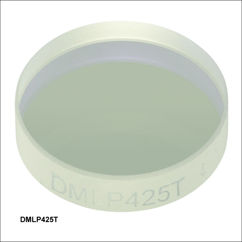
| Cut-On Wavelength | 425 nm |
| Transmission Band (Tabs > 85%, Tavg > 90%) | 440 - 800 nm |
| Reflection Band (Rabs > 90%, Ravg > 95%) | 380 - 410 nm |
| Item # | More Info |
| DMLP425T | |
| DMLP425 | |
| DMLP425L | |
| DMLP425R | |

 Zoom
Zoom
Click to Enlarge
Click Here for Raw Data from 300 - 2600 nm
The blue shaded regions denote the transmission and reflection bands for which the performance is guaranteed to meet the stated specifications. Performance outside the shaded regions will vary from lot to lot and is not guaranteed.
| Specifications | |
|---|---|
| Cut-On Wavelength | 490 nm |
| Transmission Band (Tabs > 85%, Tavg > 90%) | 505 - 800 nm |
| Reflection Band (Rabs > 90%, Ravg > 95%) | 380 - 475 nm |
| Item # | More Info |
| DMLP490T | |
| DMLP490 | |
| DMLP490L | |
| DMLP490R | |

 Zoom
Zoom
Click to Enlarge
Click Here for Raw Data from 250 - 2500 nm
The blue shaded regions denote the transmission and reflection bands for which the performance is guaranteed to meet the stated specifications. Performance outside the shaded regions will vary from lot to lot and is not guaranteed.
| Specifications | |
|---|---|
| Cut-On Wavelength | 505 nm |
| Transmission Band (Tabs > 85%, Tavg > 90%) | 520 - 800 nm |
| Reflection Band (Rabs > 90%, Ravg > 95%) | 380 - 490 nm |
| Item # | More Info |
| DMLP505T | |
| DMLP505 | |
| DMLP505L | |
| DMLP505R | |

 Zoom
Zoom
Click to Enlarge
Click Here for Raw Data from 300 - 2600 nm
The blue shaded regions denote the transmission and reflection bands for which the performance is guaranteed to meet the stated specifications. Performance outside the shaded regions will vary from lot to lot and is not guaranteed.
| Specifications | |
|---|---|
| Cut-On Wavelength | 550 nm |
| Transmission Band (Tabs > 85%, Tavg > 90%) | 565 - 800 nm |
| Reflection Band (Rabs > 90%, Ravg > 95%) | 380 - 533 nm |
| Item # | More Info |
| DMLP550T | |
| DMLP550 | |
| DMLP550L | |
| DMLP550R | |

 Zoom
Zoom
Click to Enlarge
Click Here for Raw Data from 200 - 2600 nm
The blue shaded regions denote the transmission and reflection bands for which the performance is guaranteed to meet the stated specifications. Performance outside the shaded regions will vary from lot to lot and is not guaranteed.
| Specifications | |
|---|---|
| Cut-On Wavelength | 567 nm |
| Transmission Band (Tabs > 85%, Tavg > 90%) | 584 - 800 nm |
| Reflection Band (Rabs > 90%, Ravg > 95%) | 380 - 550 nm |
| Item # | More Info |
| DMLP567T | |
| DMLP567 | |
| DMLP567L | |
| DMLP567R | |

 Zoom
Zoom
Click to Enlarge
Click Here for Raw Data from 200 - 2600 nm
The blue shaded regions denote the transmission and reflection bands for which the performance is guaranteed to meet the stated specifications. Performance outside the shaded regions will vary from lot to lot and is not guaranteed.
| Specifications | |
|---|---|
| Cut-On Wavelength | 605 nm |
| Transmission Band (Tabs > 85%, Tavg > 90%) | 620 - 800 nm |
| Reflection Band (Rabs > 90%, Ravg > 95%) | 470 - 590 nm |
| Item # | More Info |
| DMLP605T | |
| DMLP605 | |
| DMLP605L | |
| DMLP605R | |

 Zoom
Zoom
Click to Enlarge
Click Here for Raw Data from 200 - 2600 nm
The blue shaded regions denote the transmission and reflection bands for which the performance is guaranteed to meet the stated specifications. Performance outside the shaded regions will vary from lot to lot and is not guaranteed.
| Specifications | |
|---|---|
| Cut-On Wavelength | 638 nm |
| Transmission Band (Tabs > 85%, Tavg > 90%) | 655 - 700 nm |
| Reflection Band (Rabs > 90%) | 580 - 621 nm |
| Item # | More Info |
| DMLP638T | |
| DMLP638 | |
| DMLP638L | |
| DMLP638R | |

 Zoom
Zoom
Click to Enlarge
Click Here for Raw Data from 300 - 2600 nm
The blue shaded regions denote the transmission and reflection bands for which the performance is guaranteed to meet the stated specifications. Performance outside the shaded regions will vary from lot to lot and is not guaranteed.
| Specifications | |
|---|---|
| Cut-On Wavelength | 650 nm |
| Transmission Band (Tabs > 85%, Tavg > 90%) | 685 - 1600 nm |
| Reflection Band (Rabs > 90%, Ravg > 95%) | 400 - 633 nm |
| Item # | More Info |
| DMLP650T | |
| DMLP650 | |
| DMLP650L | |
| DMLP650R | |

 Zoom
Zoom
Click to Enlarge
Click Here for Raw Data from 200 - 2500 nm
The blue shaded regions denote the transmission and reflection bands for which the performance is guaranteed to meet the stated specifications. Performance outside the shaded regions will vary from lot to lot and is not guaranteed.
| Specifications | |
|---|---|
| Cut-On Wavelength | 730 nm |
| Transmission Band (Tavg > 92%) | 750 - 1100 nm |
| Transmission Band (Tavg > 94%) | 1300 - 1400 nm, 1300 - 1800 nm, 1700 - 1800 nm |
| Reflection Band (Ravg > 97%) | 450 - 690 nm |
| Item # | More Info |
| DMLP730B | |

 Zoom
Zoom
Click to Enlarge
Click Here for Raw Data from 250 - 2500 nm
The blue shaded regions denote the transmission and reflection bands for which the performance is guaranteed to meet the stated specifications. Performance outside the shaded regions will vary from lot to lot and is not guaranteed.
| Specifications | |
|---|---|
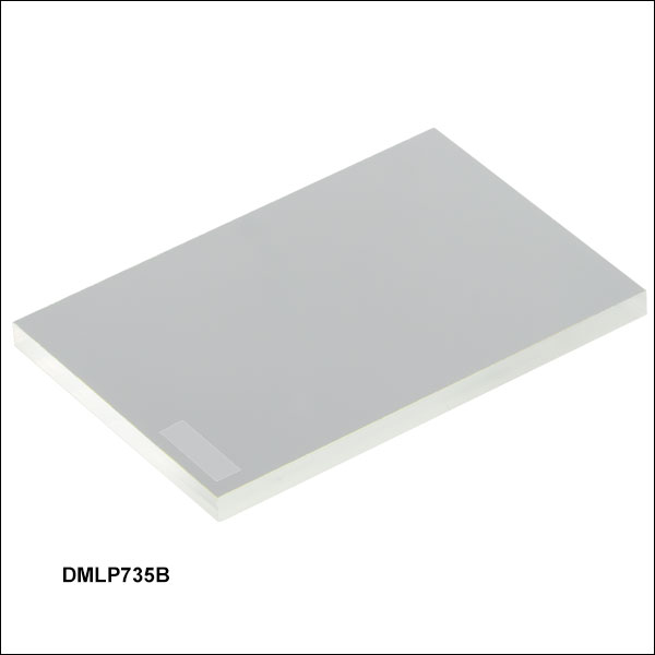
| Cut-On Wavelength | 735 nm |
| Transmission Band (Tavg > 93%) | 750 - 1600 nm |
| Reflection Band (Ravg > 98%) | 350 - 720 nm |
| Item # | More Info |
| DMLP735B | |

 Zoom
Zoom
Click to Enlarge
Click Here for Raw Data from 250 - 2500 nm
The blue shaded regions denote the transmission and reflection bands for which the performance is guaranteed to meet the stated specifications. Performance outside the shaded regions will vary from lot to lot and is not guaranteed.
| Specifications | |
|---|---|
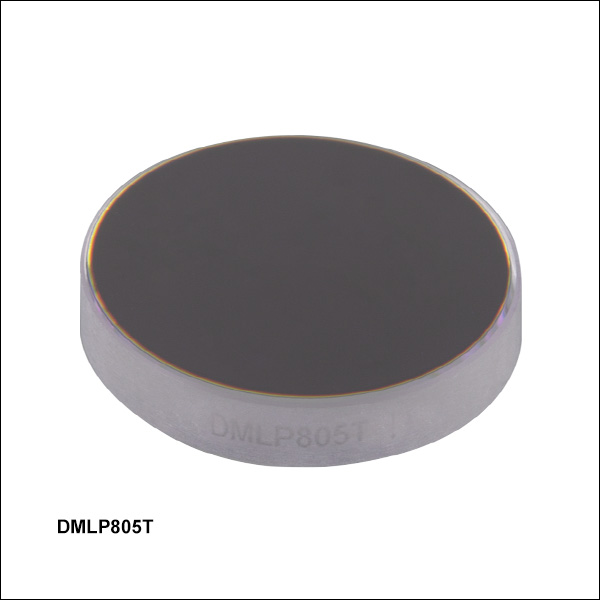
| Cut-On Wavelength | 805 nm |
| Transmission Band (Tabs > 85%, Tavg > 90%) | 825 - 1300 nm |
| Reflection Band (Rabs > 90%, Ravg > 95%) | 400 - 785 nm |
| Item # | More Info |
| DMLP805T | |
| DMLP805 | |
| DMLP805L | |
| DMLP805R | |

 Zoom
Zoom
Click to Enlarge
Click Here for Raw Data from 200 - 2600 nm
The blue shaded regions denote the transmission and reflection bands for which the performance is guaranteed to meet the stated specifications. Performance outside the shaded regions will vary from lot to lot and is not guaranteed.
| Specifications | |
|---|---|
| Cut-On Wavelength | 900 nm |
| Transmission Band (Tabs > 85%, Tavg > 90%) | 932 - 1300 nm |
| Reflection Band (Rabs > 90%) | 400 - 872 nm |
| Item # | More Info |
| DMLP900T | |
| DMLP900 | |
| DMLP900L | |
| DMLP900R | |

 Zoom
Zoom
Click to Enlarge
Click Here for Raw Data from 250 - 2500 nm
The blue shaded regions denote the transmission and reflection bands for which the performance is guaranteed to meet the stated specifications. Performance outside the shaded regions will vary from lot to lot and is not guaranteed.
| Specifications | |
|---|---|
| Cutoff Wavelength | 740 nm |
| Cut-On Wavelength | 940 nm |
| Transmission Bands (Tavg > 93%) | 400 - 725 nm, 980 - 1700 nm |
| Reflection Band (Ravg > 97%) | 753 - 935 nm |
| Item # | More Info |
| DMBP740B | |

 Zoom
Zoom
Click to Enlarge
Click Here for Raw Data from 300 - 2600 nm
The blue shaded regions denote the transmission and reflection bands for which the performance is guaranteed to meet the stated specifications. Performance outside the shaded regions will vary from lot to lot and is not guaranteed.
| Specifications | |
|---|---|
| Cut-On Wavelength | 950 nm |
| Transmission Band (Tabs > 85%, Tavg > 90%) | 990 - 1600 nm |
| Reflection Band (Rabs > 90%, Ravg > 95%) | 420 - 900 nm |
| Item # | More Info |
| DMLP950T | |
| DMLP950 | |
| DMLP950L | |
| DMLP950R | |

 Zoom
Zoom
Click to Enlarge
Click Here for Raw Data from 250 - 2500 nm
The blue shaded regions denote the transmission and reflection bands for which the performance is guaranteed to meet the stated specifications. Performance outside the shaded regions will vary from lot to lot and is not guaranteed.
| Specifications | |
|---|---|
| Cut-On Wavelength | 1000 nm |
| Transmission Band (Tabs > 85%, Tavg > 90%) | 1020 - 1550 nm |
| Reflection Band (Rabs > 90%, Ravg > 95%) | 520 - 985 nm |
| Item # | More Info |
| DMLP1000T | |
| DMLP1000 | |
| DMLP1000L | |
| DMLP1000R | |

 Zoom
Zoom
Click to Enlarge
Click Here for Raw Data from 250 - 2500 nm
The blue shaded regions denote the transmission and reflection bands for which the performance is guaranteed to meet the stated specifications. Performance outside the shaded regions will vary from lot to lot and is not guaranteed.
| Specifications | |
|---|---|
| Cut-On Wavelength | 1150 nm |
| Transmission Band (Tavg > 95%) | 1200 - 1900 nm |
| Reflection Band (Ravg > 95%) | 720 - 1100 nm |
| Item # | More Info |
| DMLP1150B | |

 Zoom
Zoom
Click to Enlarge
Click Here for Raw Data from 200 - 2600 nm
The blue shaded regions denote the transmission and reflection bands for which the performance is guaranteed to meet the stated specifications. Performance outside the shaded regions will vary from lot to lot and is not guaranteed.
| Specifications | |
|---|---|
| Cut-On Wavelength | 1180 nm |
| Transmission Band (Tabs > 85%, Tavg > 90%) | 1260 - 1700 nm |
| Reflection Band (Rabs > 90%, Ravg >95%) | 750 - 1100 nm |
| Item # | More Info |
| DMLP1180T | |
| DMLP1180 | |
| DMLP1180L | |
| DMLP1180R | |

 Zoom
Zoom
Click to Enlarge
Click Here for Raw Data from 250 - 2500 nm
The blue shaded regions denote the transmission and reflection bands for which the performance is guaranteed to meet the stated specifications. Performance outside the shaded regions will vary from lot to lot and is not guaranteed.
| Specifications | |
|---|---|
| Cut-On Wavelength | 1500 nm |
| Transmission Band (Tabs > 85%, Tavg > 90%) | 1550 - 2000 nm |
| Reflection Band (Rabs > 90%, Ravg > 95%) | 1000 - 1450 nm |
| Item # | More Info |
| DMLP1500T | |
| DMLP1500 | |
| DMLP1500L | |
| DMLP1500R | |

 Zoom
Zoom
Click to Enlarge
Click Here for Raw Data from 250 - 2500 nm
The blue shaded regions denote the transmission and reflection bands for which the performance is guaranteed to meet the stated specifications. Performance outside the shaded regions will vary from lot to lot and is not guaranteed.
| Specifications | |
|---|---|
| Cut-On Wavelength | 1800 nm |
| Transmission Band (Tabs > 85%, Tavg > 90%) | 1850 - 2100 nm |
| Reflection Band (Rabs > 90%, Ravg > 95%) | 1500 - 1750 nm |
| Item # | More Info |
| DMLP1800T | |
| DMLP1800 | |
| DMLP1800L | |
| DMLP1800R | |