 Products Home / Detectors / Amplified Detectors / Si Amplified Detectors / Si Free-Space Amplified Photodetectors
Si Free-Space Amplified Photodetectors
- Wavelength Ranges from 200 nm to 1100 nm
- Maximum Bandwidths Up to 1.5 GHz
- Sensitivities Down to Femtowatt Powers
- Fixed and Switchable Gain Versions
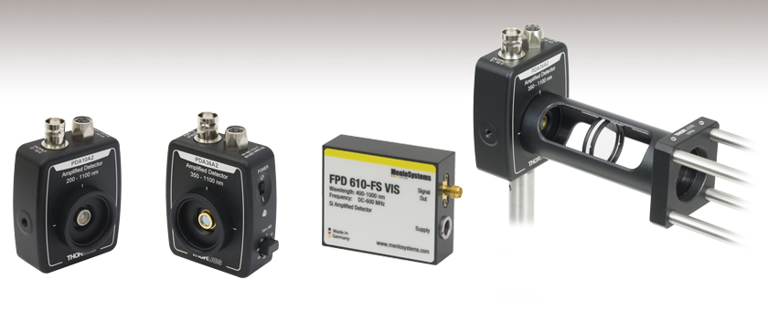
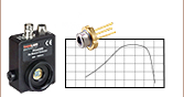
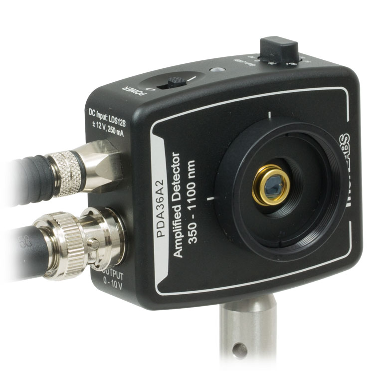
PDA36A2
Switchable Gain
12 MHz Max Bandwidth
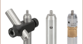
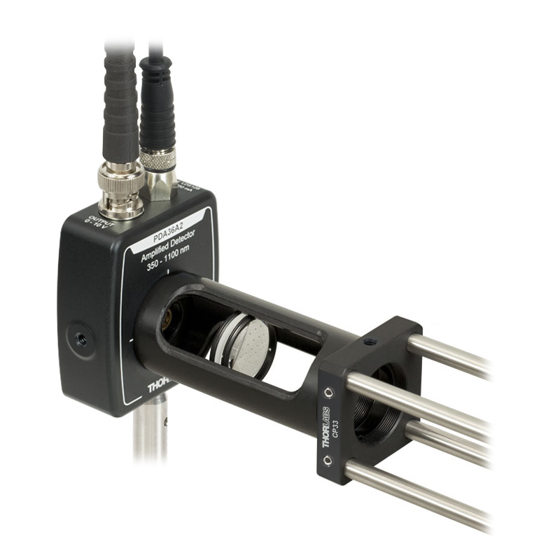
Application Idea
PDA Series Detector with Ø1" Lens Tube Attached to a 30 mm Cage System
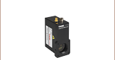
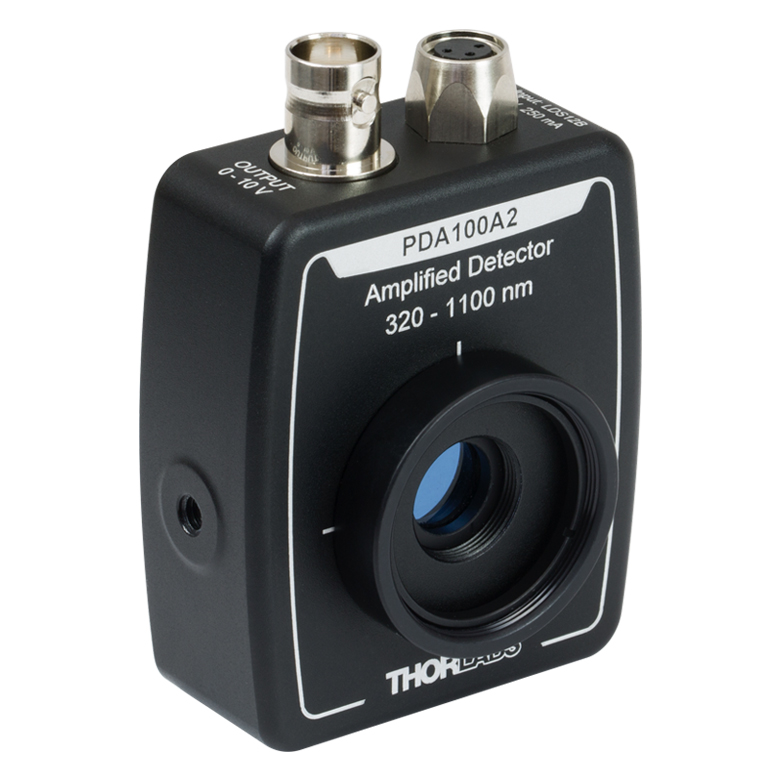
PDA10A2
Fixed Gain
150 MHz Max Bandwidth
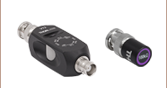
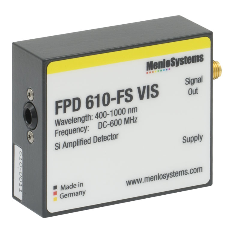
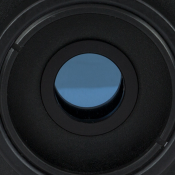
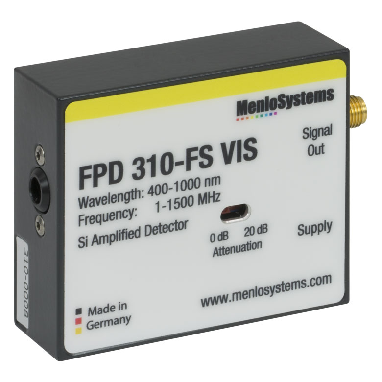
FPD610-FS-VIS
Fixed Gain
600 MHz Max Bandwidth


Please Wait
| Item # | Wavelength Range | Bandwidth | NEP |
|---|---|---|---|
| Fixed Gain | |||
| PDA10A2 | 200 - 1100 nm | DC - 150 MHz | 29.2 pW/Hz1/2 |
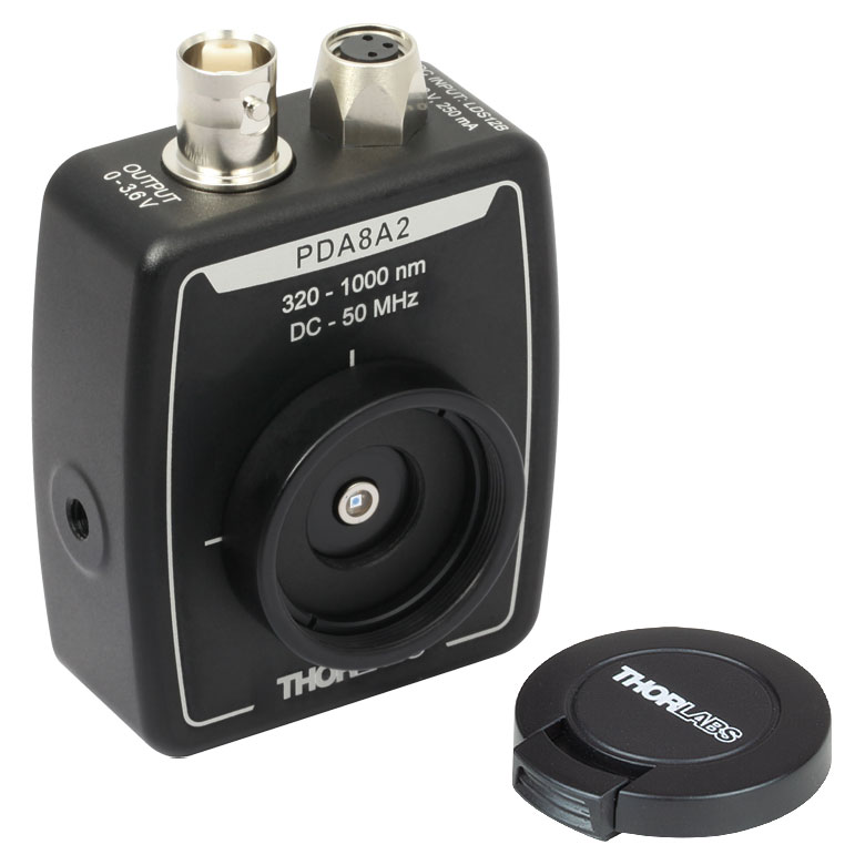
| PDA8A2 | 320 - 1000 nm | DC - 50 MHz | 7.8 pW/Hz1/2 |
| PDF10A2 | 320 - 1100 nm | DC - 20 Hz | 3.0 x 10⁻³ pW/Hz1/2 |
| PDA015A2 | 400 - 1000 nm | DC - 380 MHz | 36 pW/Hz1/2 |
| FPD510-FS-VIS | 400 - 1000 nm | DC - 250 MHz | 6.0 pW/Hz1/2 |
| FPD610-FS-VIS | 400 - 1000 nm | DC - 600 MHz | 11.2 pW/Hz1/2 |
| Switchable Gain | |||
| PDA100A2a | 320 - 1100 nm | DC - 11 MHz | 2.67 - 71.7 pW/Hz1/2 |
| PDA36A2a | 350 - 1100 nm | DC - 12 MHz | 3.25 - 75.7 pW/Hz1/2 |
| FPD310-FS-VISb | 400 - 1000 nm | 1 - 1500 MHz | 24.0 pW/Hz1/2 |
Features
- Wavelength Ranges within 200 to 1100 nm
- Low-Noise Amplification with Fixed or Switchable Gain
- Load Impedances 50 Ω and Higher for ≥3 kHz Bandwidth Versions
- Free-Space Optical Coupling
We offer a selection of Silicon (Si) Free-Space Amplified Photodetectors that are sensitive to light in the UV to the NIR wavelength range. Thorlabs' amplified photodetectors feature a built-in low-noise transimpedance amplifier (TIA) or a low-noise TIA followed by a voltage amplifier. Menlo Systems' FPD series amplified photodetectors have a built-in radio frequency (RF) or transimpedance amplifier. We offer fixed-gain versions that possess a fixed maximum bandwidth and total transimpedance gain, as well as switchable-gain versions with two or eight gain settings.
Thorlabs' photodetectors are designed to meet a range of requirements, with offerings that include the 380 MHz PDA015A2 fixed-gain detector with an impulse response of 1 ns, the high-sensitivity PDF10A2 detector with a minimum noise equivalent power (NEP) of 3.0 fW/Hz1/2, and the switchable-gain PDA100A2 device with eight switchable maximum gain (bandwidth) combinations from 1.51 kV/A (11 MHz) to 4.75 MV/A (3 kHz). The PDF10A2 with femtowatt sensitivity is a low-frequency device that should only be terminated into high impedance (Hi-Z) loads, while all other of our silicon amplified photodetectors are capable of driving loads from 50 Ω to Hi-Z.

Click to Enlarge
The PDA10A2 with the Included ±12 V Power Supply. Replacement power supplies are sold below.
Every detector has internal SM05 (0.535"-40) threading and external SM1 (1.035"-40) threading. Each unit's housing features universal taps that accept both 8-32 and M4. For more information about the location of these mounting points and mounting these units, please see the Housing Features and Mounting Options tabs.
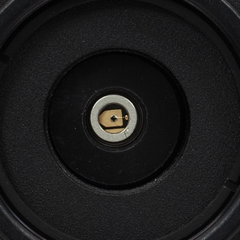
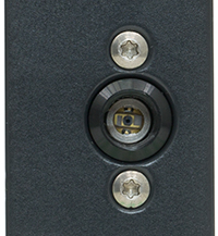
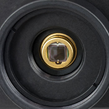
Menlo Systems' FPD series detectors are easy-to-use photodiode packages with an integrated high-gain, low-noise RF (FPD310-FS-VIS) or transimpedance (FPD510-FS-VIS and FPD610-FS-VIS) amplifier. The FPD310-FS-VIS detector is ideal for experiments requiring high bandwidths and extremely short rise times (<1 ns). This detector has a switchable gain with two steps, 0 and 20 dB. The FPD510-FS-VIS and FPD610-FS-VIS fixed-gain detectors are optimized for the highest signal-to-noise ratio when detecting low-level optical beat signals at frequencies up to 250 MHz and 600 MHz, respectively. The FPD510-FS-VIS detector has a rise time of 2 ns, while the FPD610-FS-VIS device has a 1 ns rise time. The 3 dB bandwidth of these DC-coupled devices is 200 MHz for the FPD510-FS-VIS and 500 MHz for the FPD610-FS-VIS. The compact design of the FPD detectors allows for easy OEM integration. The housing of each Menlo detector features one M4 tapped hole for post mounting. For more information about the housing, please see the Housing Features tab. For versions of these detectors with FC/PC inputs, see Si Fiber-Coupled Amplified Detectors.

Click to Enlarge
Menlo Systems’ Detectors Include a Location-Specific ±12 V Power Supply
Power Supply
A ±12 V linear power supply that supports input voltages of 100, 120, and 230 VAC is included with each amplified photodetector. Replacement power supplies are available separately below. Before connecting the power supply to mains voltage, ensure that the mains voltage switch on the power supply module is set to the proper voltage range. The power supplies should always be powered up using the power switch on the power supply itself. Hot plugging the unit is not recommended.
Menlo's FPD510-FS-VIS, FPD610-FS-VIS, and FPD310-FS-VIS detectors include a low-noise power supply.
Performance Specifications
| Item # | Wavelength | Bandwidth | Rise Time | Peak Responsivity | Noise Equivalent Power (NEP)a |
Active Area | Operating Temperataure Range |
|---|---|---|---|---|---|---|---|
| Fixed Gain | |||||||
| PDA10A2b | 200 - 1100 nmc | DC - 150 MHz | 2.3 ns | 0.44 A/W @ 730 nm | 29.2 pW/Hz1/2 | 0.8 mm2 (Ø1 mm) | 10 to 50 °C |
| PDA8A2 | 320 - 1000 nm | DC - 50 MHz | 7 ns | 0.56 A/W @ 820 nm | 7.8 pW/Hz1/2 | 0.5 mm2 (Ø0.8 mm) | 10 to 50 °C |
| PDF10A2 | 320 - 1100 nm | DC - 20 Hz | 22 ms | 0.6 A/W @ 960 nm | 3.0 x10⁻³ pW/Hz1/2 | 1.2 mm2 (1.1 mm x 1.1 mm) | 10 to 50 °C |
| PDA015A2b | 400 - 1000 nm | DC - 380 MHz | 1.0 ns | 0.47 A/W @ 740 nm | 36 pW/Hz1/2 | 0.018 mm2 (Ø150 µm) | 10 to 40 °C |
| FPD510-FS-VIS | 400 - 1000 nm | DC - 250 MHz | 2 ns | - | 6.0 pW/Hz1/2 | 0.13 mm2 (Ø0.4 mm) | 10 to 40 °C |
| FPD610-FS-VIS | 400 - 1000 nm | DC - 600 MHz | 1 ns | - | 11.2 pW/Hz1/2 | 0.13 mm2 (Ø0.4 mm) | 10 to 40 °C |
| Switchable Gain | |||||||
| PDA100A2b | 320 - 1100 nm | DC - 11 MHzd | N/Ae | 0.72 A/W @ 960 nm | 2.67 - 71.7 pW/Hz1/2 | 75.4 mm2 (Ø9.8 mm) | 10 to 40 °C |
| PDA36A2b | 350 - 1100 nm | DC - 12 MHzd | N/Ae | 0.65 A/W @ 970 nm | 3.25 - 75.7 pW/Hz1/2 | 13 mm2 (3.6 mm x 3.6 mm) | 10 to 40 °C |
| FPD310-FS-VIS | 400 - 1000 nm | 1 - 1500 MHz | 0.5 ns | - | 24.0 pW/Hz1/2 | 0.13 mm2 (Ø0.4 mm) | 10 to 40 °C |
Gain Specifications
Fixed Gain Detectors
| Item # | Gain w/ Hi-Z Load | Gain w/ 50 Ω Load | Offset (±) | Output Voltage w/ Hi-Z Load |
Output Voltage w/ 50 Ω Load |
|---|---|---|---|---|---|
| PDA10A2 | 10 kV/A | 5 kV/A | 10 mV | 0 - 10 V | 0 - 5 V |
| PDA8A2 | 100 kV/A | 50 kV/A | 10 mV (Max) | 0 - 3.6 V | 0 - 1.8 V |
| PDF10A2a | 1 x 10⁹ kV/A | - | <75 mV | 0 - 10 V | - |
| PDA015A2 | 50 kV/A | 25 kV/A | 20 mV | 0 - 10 V | 0 - 5 V |
| FPD510-FS-VIS | - | 1.5 x 10⁵ Vpp/Wb 2.5 x 10⁴ Vpp/Wc |
- | - | 0 - 1 V |
| FPD610-FS-VIS | - | 2 x 10⁶ Vpp/Wb 2.5 x 10⁵ Vpp/Wc |
- | - | 0 - 1 V |
Switchable Gain Detectors
| Item # | Gain Step (dB) |
Gain w/ Hi-Z Loada |
Gain w/ 50 Ω Loada |
Bandwidth | Noise (RMS) |
NEPb | Offset (±) | Output Voltage w/ Hi-Z Load |
Output Voltage w/ 50 Ω Load |
|---|---|---|---|---|---|---|---|---|---|
| PDA100A2 | 0 | 1.51 kV/A | 0.75 kV/A | 11 MHz | 268 µV | 71.7 pW/Hz1/2 | 8 mV (12 mV Max) | 0 - 10 V | 0 - 5 V |
| 10 | 4.75 kV/A | 2.38 kV/A | 1.4 MHz | 195 µV | 6.75 pW/Hz1/2 | ||||
| 20 | 15 kV/A | 7.5 kV/A | 800 kHz | 219 µV | 3.36 pW/Hz1/2 | ||||
| 30 | 47.5 kV/A | 23.8 kV/A | 260 kHz | 222 µV | 2.83 pW/Hz1/2 | ||||
| 40 | 151 kV/A | 75 kV/A | 90 kHz | 229 µV | 2.67 pW/Hz1/2 | ||||
| 50 | 475 kV/A | 238 kV/A | 28 kHz | 271 µV | 4.2 pW/Hz1/2 | ||||
| 60 | 1.5 MV/A | 750 kV/A | 9 kHz | 423 µV | 6.24 pW/Hz1/2 | ||||
| 70 | 4.75 MV/A | 2.38 MV/A | 3 kHz | 1.22 mV | 7.88 pW/Hz1/2 | ||||
| PDA36A2 | 0 | 1.51 kV/A | 0.75 kV/A | 12 MHz | 258 µV | 75.7 pW/Hz1/2 | 8 mV (12 mV Max) | 0 - 10 V | 0 - 5 V |
| 10 | 4.75 kV/A | 2.38 kV/A | 1.6 MHz | 192 µV | 5.8 pW/Hz1/2 | ||||
| 20 | 15 kV/A | 7.5 kV/A | 1 MHz | 207 µV | 3.4 pW/Hz1/2 | ||||
| 30 | 47.5 kV/A | 23.8 kV/A | 260 kHz | 211 µV | 3.4 pW/Hz1/2 | ||||
| 40 | 150 kV/A | 75 kV/A | 90 kHz | 214 µV | 3.25 pW/Hz1/2 | ||||
| 50 | 475 kV/A | 238 kV/A | 28 kHz | 234 µV | 3.69 pW/Hz1/2 | ||||
| 60 | 1.5 MV/A | 750 kV/A | 9 kHz | 277 µV | 4 pW/Hz1/2 | ||||
| 70 | 4.75 MV/A | 2.38 MV/A | 3 kHz | 388 µV | 4.29 pW/Hz1/2 | ||||
| FPD310-FS-VIS | 0 | - | 2 x 10⁴ Vpp/Wc 1.3 x 10³ Vpp/Wd |
1 - 1500 MHz | -e | 24.0 pW/Hz1/2 | N/A (AC Coupling) | - | ~1 V |
| 20 | - | 2 x 10³ Vpp/Wc 1.3 x 10² Vpp/Wd |
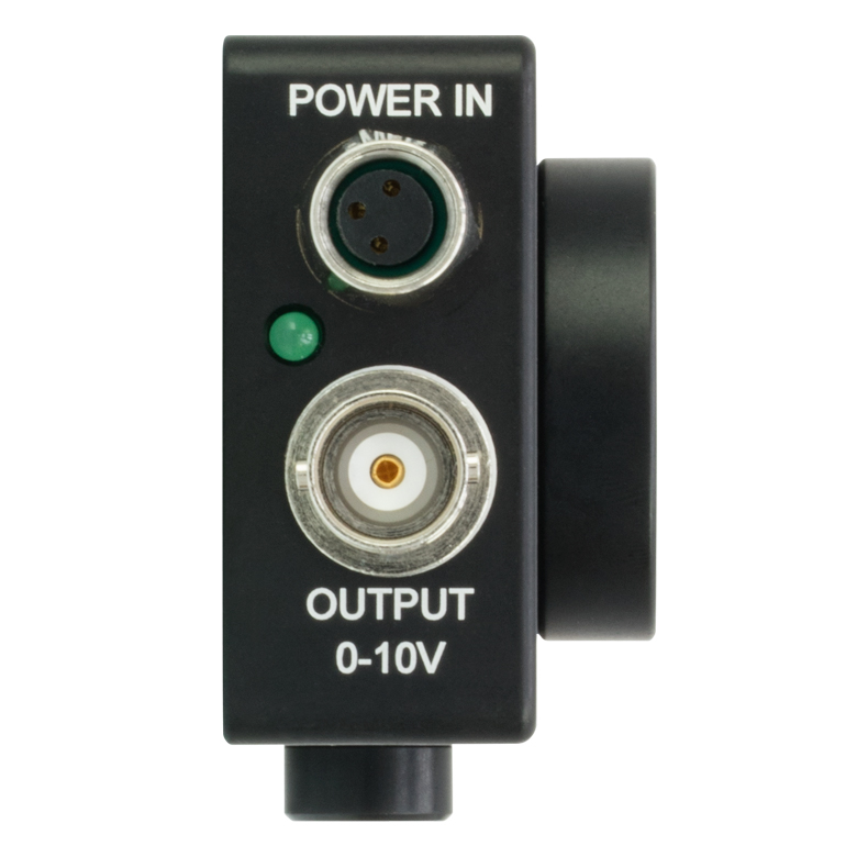
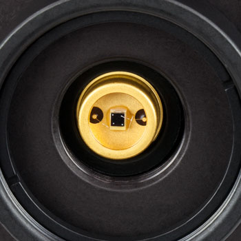
Click to Enlarge
Top of the housing on our PDA and PDF detector housings. The Power In connector, Output BNC connector, and power indicator LED are located at the top of the housing. The PDA015A detector is shown.
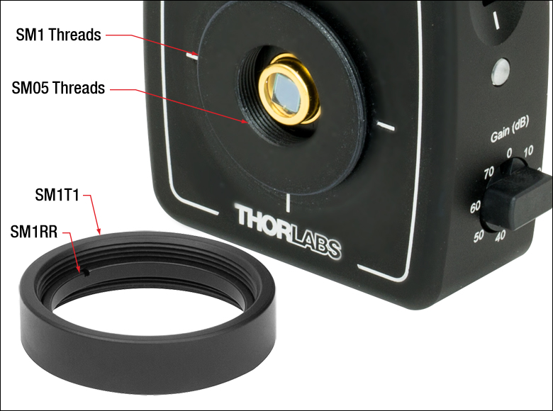
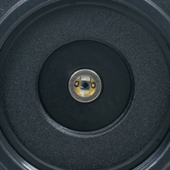
Click to Enlarge
The housings of Thorlabs' detectors feature internal SM05 and external SM1 threads. An SM1T1 SM1 Adapter with internal threads is included with each amplified photodetector, and an SM1RR Retaining Ring is included with the PDA015A, PDA10A2, PDA36A2, PDA100A2, and PDF10A2.
Housing Features of the Amplified Si Photodetectors
Please refer to the table below for detailed drawings of each detector.
PDA and PDF Detectors
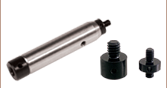
Thorlabs' Amplified Photodiode series feature a slim design with many common elements. Each housing features internal SM05 (0.535"-40) threading and external SM1 (1.035"-40) threading, and includes a detachable SM1T1 internally SM1-threaded adapter, as shown to the right. The SM1T1 can hold up to 0.1" (2.8 mm) thick optics. An SM1RR retaining ring is included with every detector. Each detector can be mounted using a 1/2" Post, as shown in the images below. Detectors with universal taps (refer to the table below) have a new housing design that features the active area flush with the front of the housing, simplifying alignments within optomechanical systems. As a convenience, the back panels of these detectors are engraved with the responsivity curve of the photodiodes.
Lens Tube Compatibility
These detectors can be integrated into various optomechanical systems using the internal SM05 and external SM1 threads. A lens tube can be directly attached to the SM1 threads, making the detectors compatible with lens tube systems. The SM1T1 adapter can be used to mount Ø1" (Ø25.4 mm) optical components, such as optical filters and lenses.
Cage System Compatibility
The detectors are also cage system compatible, as shown in the two images below right. A CP33 cage plate can be attached directly to the SM1 threads. This attachment method does not require an adapter piece and allows the diode to be as close as possible to the cage plate, which can be important in setups where the light is divergent. Another method for integrating a detector into a cage system is using the included SM1T1 with an SM1T2 adapter. This allows more freedom in choosing the orientation of the detector. Additionally, these detectors can be used with SM1-threaded fiber adapters (sold below).
Post Mounting
Threaded holes on the housings of the detectors allow the units to be mounted in a horizontal or vertical orientation using a 1/2" Post. This gives the user the option to route the power and BNC cables from above or alongside the beam path, as shown below left. We offer detectors that have metric and imperial versions, as well as detectors that have universal mounting holes that accept 8-32 and M4 threads. Please see the table below for the specific mounting taps of each detector.
Click to Enlarge
PDA Photodetector Mounted Horizontally
Click to Enlarge
PDA Photodetector Connected to an SM1 Lens Tube in a 30 mm Cage System
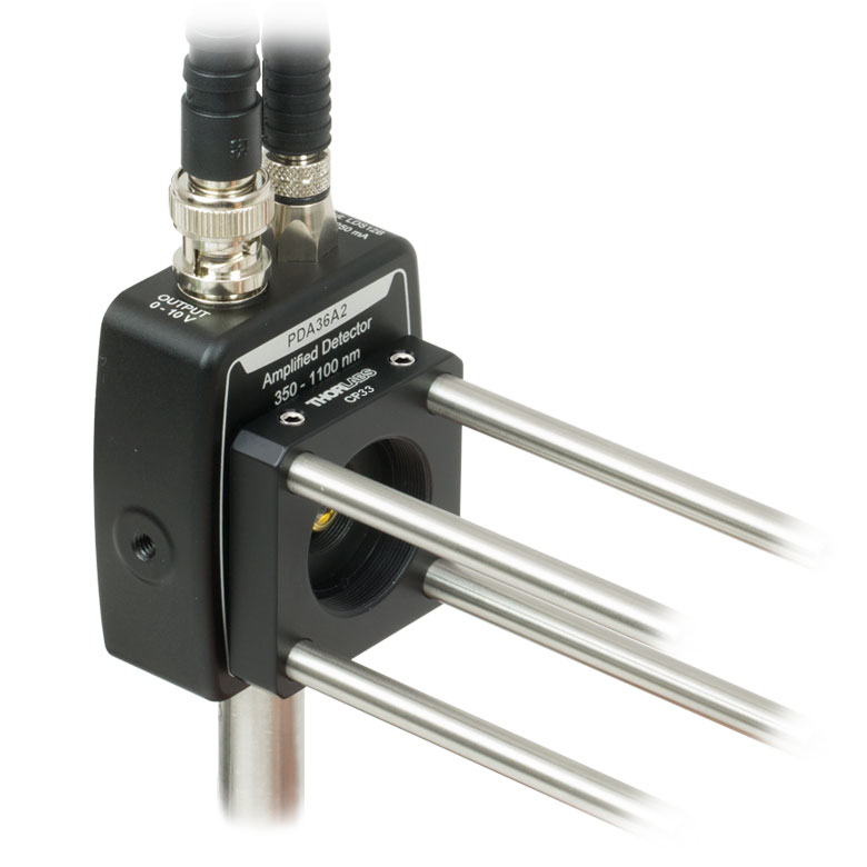
Click to Enlarge
PDA Photodetector Integrated into a 30 mm Cage System Using the External SM1 Threads
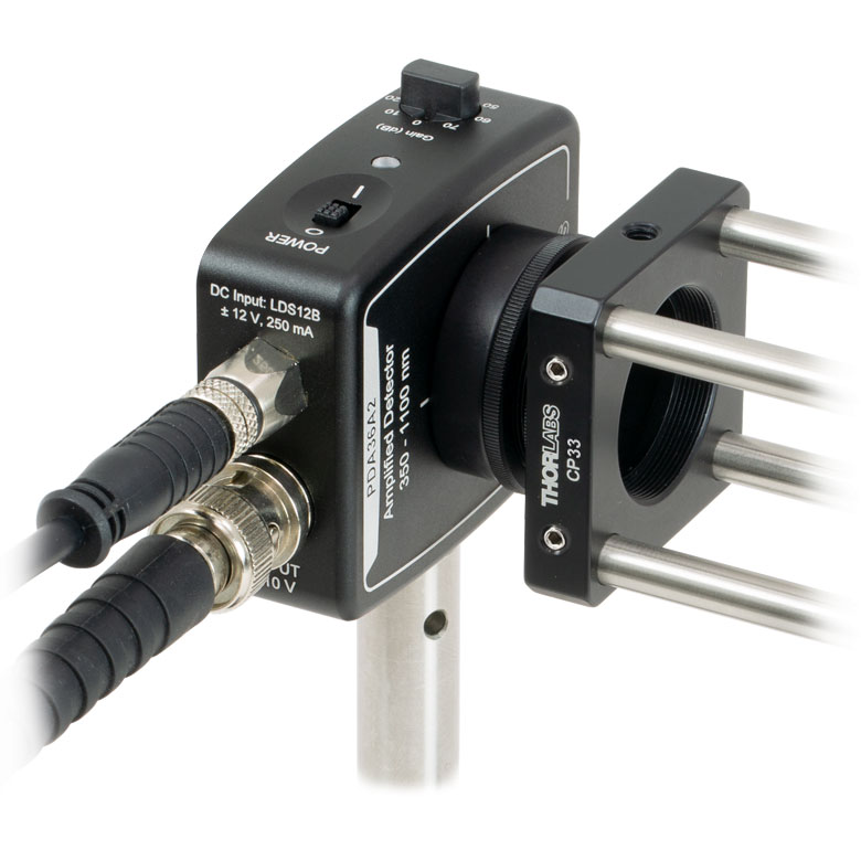
Click to Enlarge
PDA Photodetector Integrated into a 30 mm Cage System Using the SM1T1 (included) and SM1T2 Adapter
FPD Detectors
The housing of each of Menlo Systems' FPD detectors feature one M4 tapped hole on the bottom for post mounting. The power supply connector and output SMA connector are located on the side of the housing.
| Detectors | Housing Drawing (Click Icon for Details) |
Mounting Taps | SM Thread Compatibility | Dimensions | Output Connector |
|---|---|---|---|---|---|
| PDA/PDF Fixed Gain | |||||
| PDA8A2, PDA10A2, PDF10A2 |  |
Two Universal Taps for 8-32 and M4 |
Internal SM05 (0.535"-40) External SM1 (1.035"-40) |
1.96" x 0.89" x 2.79" (49.8 mm x 22.5 mm x 70.9 mm) |
BNC |
| PDA015A2 |  |
Two Universal Taps for 8-32 and M4 | 1.96" x 0.89" x 2.79" (49.8 mm x 22.5 mm x 70.9mm) |
||
| PDA8A | Three 8-32 Taps (M4 for Metric Version) |
1.70" x 0.83" x 2.57" (43.2 mm x 21.1 mm x 65.3 mm) |
|||
| FPD Fixed Gain | |||||
| FPD510-FS-VIS, FPD610-FS-VIS |
One M4 Tap | N/A | 2.36" x 0.79" x 1.97" (60.0 mm x 20.0 mm x 50.0 mm) |
SMA | |
| PDA Switchable Gain | |||||
| PDA36A2, PDA100A2 | Two Universal Taps for 8-32 and M4 |
Internal SM05 (0.535"-40) External SM1 (1.035"-40) |
2.07" x 0.89" x 2.79" (52.5 mm x 22.5 mm x 70.9 mm) |
BNC | |
| FPD Switchable Gain | |||||
| FPD310-FS-VIS | One M4 Tap | N/A | 2.36" x 0.79" x 1.97" (60.0 mm x 20.0 mm x 50.0 mm) |
SMA | |
PDA and PDF Series Detectors
BNC Female Output (Photodetector)
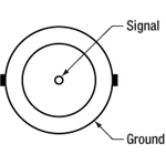
PDA10A2, PDA8A2, PDF10A2, PDA015A, PDA100A2, PDA36A2: 0 - 10 V Output
Male (Power Cables)
Female Power IN (Photodetector)
FPD Series Detectors
Signal Out- SMA Female (Photodetector)
For connection to a suitable monitoring device, e.g. oscilloscope or RF-spectrum-analyzer, with 50 Ω impedance.
Female (Power Cables)
Male Power IN (Photodetector)
Photodiode Tutorial
Theory of Operation
A junction photodiode is an intrinsic device that behaves similarly to an ordinary signal diode, but it generates a photocurrent when light is absorbed in the depleted region of the junction semiconductor. A photodiode is a fast, highly linear device that exhibits high quantum efficiency and may be used in a variety of different applications.
It is necessary to be able to correctly determine the level of the output current to expect and the responsivity based upon the incident light. Depicted in Figure 1 is a junction photodiode model with basic discrete components to help visualize the main characteristics and gain a better understanding of the operation of Thorlabs' photodiodes.
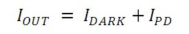
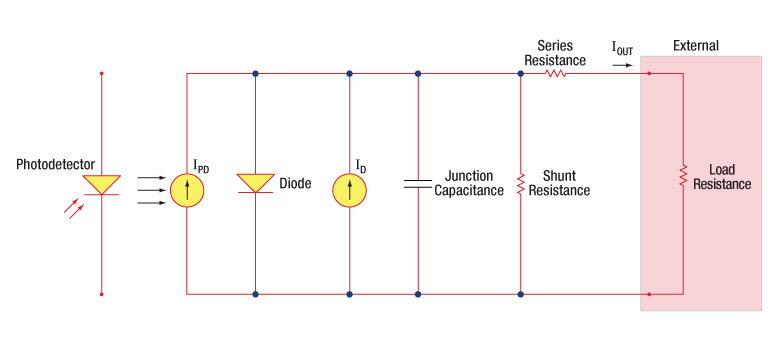
Figure 1: Photodiode Model
Photodiode Terminology
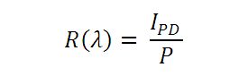
Responsivity
The responsivity of a photodiode can be defined as a ratio of generated photocurrent (IPD) to the incident light power (P) at a given wavelength:
Modes of Operation (Photoconductive vs. Photovoltaic)
A photodiode can be operated in one of two modes: photoconductive (reverse bias) or photovoltaic (zero-bias). Mode selection depends upon the application's speed requirements and the amount of tolerable dark current (leakage current).
Photoconductive
In photoconductive mode, an external reverse bias is applied, which is the basis for our DET series detectors. The current measured through the circuit indicates illumination of the device; the measured output current is linearly proportional to the input optical power. Applying a reverse bias increases the width of the depletion junction producing an increased responsivity with a decrease in junction capacitance and produces a very linear response. Operating under these conditions does tend to produce a larger dark current, but this can be limited based upon the photodiode material. (Note: Our DET detectors are reverse biased and cannot be operated under a forward bias.)
Photovoltaic
In photovoltaic mode the photodiode is zero biased. The flow of current out of the device is restricted and a voltage builds up. This mode of operation exploits the photovoltaic effect, which is the basis for solar cells. The amount of dark current is kept at a minimum when operating in photovoltaic mode.
Dark Current
Dark current is leakage current that flows when a bias voltage is applied to a photodiode. When operating in a photoconductive mode, there tends to be a higher dark current that varies directly with temperature. Dark current approximately doubles for every 10 °C increase in temperature, and shunt resistance tends to double for every 6 °C rise. Of course, applying a higher bias will decrease the junction capacitance but will increase the amount of dark current present.
The dark current present is also affected by the photodiode material and the size of the active area. Silicon devices generally produce low dark current compared to germanium devices which have high dark currents. The table below lists several photodiode materials and their relative dark currents, speeds, sensitivity, and costs.
| Material | Dark Current | Speed | Spectral Range | Cost |
|---|---|---|---|---|
| Silicon (Si) | Low | High Speed | Visible to NIR | Low |
| Germanium (Ge) | High | Low Speed | NIR | Low |
| Gallium Phosphide (GaP) | Low | High Speed | UV to Visible | Moderate |
| Indium Gallium Arsenide (InGaAs) | Low | High Speed | NIR | Moderate |
| Indium Arsenide Antimonide (InAsSb) | High | Low Speed | NIR to MIR | High |
| Extended Range Indium Gallium Arsenide (InGaAs) | High | High Speed | NIR | High |
| Mercury Cadmium Telluride (MCT, HgCdTe) | High | Low Speed | NIR to MIR | High |
Junction Capacitance
Junction capacitance (Cj) is an important property of a photodiode as this can have a profound impact on the photodiode's bandwidth and response. It should be noted that larger diode areas encompass a greater junction volume with increased charge capacity. In a reverse bias application, the depletion width of the junction is increased, thus effectively reducing the junction capacitance and increasing the response speed.
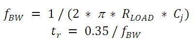
Bandwidth and Response
A load resistor will react with the photodetector junction capacitance to limit the bandwidth. For best frequency response, a 50 Ω terminator should be used in conjunction with a 50 Ω coaxial cable. The bandwidth (fBW) and the rise time response (tr) can be approximated using the junction capacitance (Cj) and the load resistance (RLOAD):
Noise Equivalent Power
The noise equivalent power (NEP) is the generated RMS signal voltage generated when the signal to noise ratio is equal to one. This is useful, as the NEP determines the ability of the detector to detect low level light. In general, the NEP increases with the active area of the detector and is given by the following equation:
Here, S/N is the Signal to Noise Ratio, Δf is the Noise Bandwidth, and Incident Energy has units of W/cm2. For more information on NEP, please see Thorlabs' Noise Equivalent Power White Paper.
Terminating Resistance
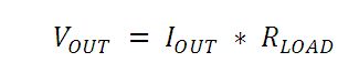
A load resistance is used to convert the generated photocurrent into a voltage (VOUT) for viewing on an oscilloscope:
Depending on the type of the photodiode, load resistance can affect the response speed. For maximum bandwidth, we recommend using a 50 Ω coaxial cable with a 50 Ω terminating resistor at the opposite end of the cable. This will minimize ringing by matching the cable with its characteristic impedance. If bandwidth is not important, you may increase the amount of voltage for a given light level by increasing RLOAD. In an unmatched termination, the length of the coaxial cable can have a profound impact on the response, so it is recommended to keep the cable as short as possible.
Shunt Resistance
Shunt resistance represents the resistance of the zero-biased photodiode junction. An ideal photodiode will have an infinite shunt resistance, but actual values may range from the order of ten Ω to thousands of MΩ and is dependent on the photodiode material. For example, and InGaAs detector has a shunt resistance on the order of 10 MΩ while a Ge detector is in the kΩ range. This can significantly impact the noise current on the photodiode. For most applications, however, the high resistance produces little effect and can be ignored.
Series Resistance
Series resistance is the resistance of the semiconductor material, and this low resistance can generally be ignored. The series resistance arises from the contacts and the wire bonds of the photodiode and is used to mainly determine the linearity of the photodiode under zero bias conditions.
Common Operating Circuits
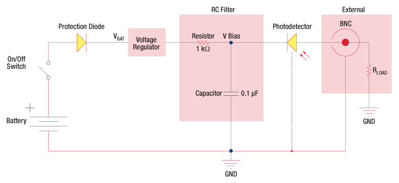
Figure 2: Reverse-Biased Circuit (DET Series Detectors)
The DET series detectors are modeled with the circuit depicted above. The detector is reverse biased to produce a linear response to the applied input light. The amount of photocurrent generated is based upon the incident light and wavelength and can be viewed on an oscilloscope by attaching a load resistance on the output. The function of the RC filter is to filter any high-frequency noise from the input supply that may contribute to a noisy output.
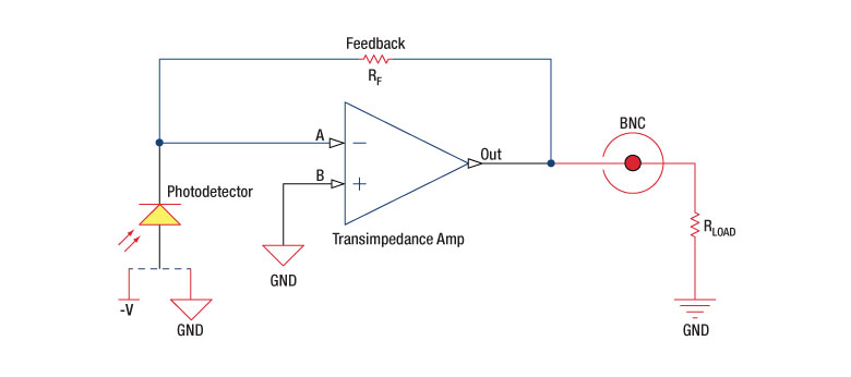
Figure 3: Amplified Detector Circuit
One can also use a photodetector with an amplifier for the purpose of achieving high gain. The user can choose whether to operate in Photovoltaic of Photoconductive modes. There are a few benefits of choosing this active circuit:
- Photovoltaic mode: The circuit is held at zero volts across the photodiode, since point A is held at the same potential as point B by the operational amplifier. This eliminates the possibility of dark current.
- Photoconductive mode: The photodiode is reversed biased, thus improving the bandwidth while lowering the junction capacitance. The gain of the detector is dependent on the feedback element (Rf). The bandwidth of the detector can be calculated using the following:
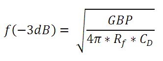
where GBP is the amplifier gain bandwidth product and CD is the sum of the junction capacitance and amplifier capacitance.
Effects of Chopping Frequency
The photoconductor signal will remain constant up to the time constant response limit. Many detectors, including PbS, PbSe, HgCdTe (MCT), and InAsSb, have a typical 1/f noise spectrum (i.e., the noise decreases as chopping frequency increases), which has a profound impact on the time constant at lower frequencies.
The detector will exhibit lower responsivity at lower chopping frequencies. Frequency response and detectivity are maximized for
![]()
The following table lists Thorlab's selection of previous and current generation PDA, PDF, and DET detectors.
| Previous Generation Cross Reference of PDA and DET Detectors | |||||
|---|---|---|---|---|---|
| Wavelength | Material | Biased Detector |
Amplified Detector |
||
| Current Generation | Previous Generation | Current Generation | Previous Generation | ||
| 200 - 1100 nm | Si | DET10A2 | DET10A(/M) | PDA10A2 | PDA10A(-EC) |
| 320 - 1000 nm | Si | - | - | PDA8A2 | PDA8A |
| 400 - 1000 nm | Si | - | - | PDA015A2 | PDA015A(/M) |
| 320 - 1100 nm | Si | DET100A2 | DET100A(/M)a | PDA100A2 | PDA100A(-EC)b |
| Si | - | - | PDF10A2 | PDF10A(/M) | |
| 350 - 1100 nm | Si | DET36A2 | DET36A(/M) | PDA36A2 | PDA36A(-EC) |
| 500 - 1700 nm | InGaAs | DET10N2 | DET10N(/M) | - | - |
| 800 - 1700 nm | InGaAs | DET20C2 | DET20C(/M) | PDA20CS2 | PDA20CS(-EC) |
| - | - | PDA05CF2 | PDA10CF(-EC) | ||
| - | - | PDA015C2 | PDA015C(/M) | ||
| - | - | PDF10C2 | PDF10C(/M) | ||
| - | - | PDA20C2 | PDA20C(/M) | ||
| 800 - 1800 nm | Ge | DET30B2 | DET30B(/M) | PDA30B2 | PDA30B(-EC) |
| DET50B2 | DET50B(/M) | PDA50B2 | PDA50B(-EC) | ||
| 900 - 1700 nm | InGaAs | DET10C2 | DET10C(/M) | PDA10CS2 | PDA10CS(-EC) |
| 900 - 2600 nm | InGaAs | DET05D2 | DET05D(/M)c | PDA10D2 | PDA10D(-EC)c |
| DET10D2 | DET10D(/M)c | - | - | ||
Pulsed Laser Emission: Power and Energy Calculations

Determining whether emission from a pulsed laser is compatible with a device or application can require referencing parameters that are not supplied by the laser's manufacturer. When this is the case, the necessary parameters can typically be calculated from the available information. Calculating peak pulse power, average power, pulse energy, and related parameters can be necessary to achieve desired outcomes including:
- Protecting biological samples from harm.
- Measuring the pulsed laser emission without damaging photodetectors and other sensors.
- Exciting fluorescence and non-linear effects in materials.
Pulsed laser radiation parameters are illustrated in Figure 1 and described in the table. For quick reference, a list of equations are provided below. The document available for download provides this information, as well as an introduction to pulsed laser emission, an overview of relationships among the different parameters, and guidance for applying the calculations.
|
Equations: |
||||
 |
and |  |
||
 |
||||
 |
||||
 |
||||
Peak power and average power calculated from each other: |
||||
 |
and |  |
||
| Peak power calculated from average power and duty cycle*: | ||||
 |
*Duty cycle ( ) is the fraction of time during which there is laser pulse emission. ) is the fraction of time during which there is laser pulse emission. |
|||
Click to Enlarge
Figure 1: Parameters used to describe pulsed laser emission are indicated in the plot (above) and described in the table (below). Pulse energy (E) is the shaded area under the pulse curve. Pulse energy is, equivalently, the area of the diagonally hashed region.
| Parameter | Symbol | Units | Description | ||
|---|---|---|---|---|---|
| Pulse Energy | E | Joules [J] | A measure of one pulse's total emission, which is the only light emitted by the laser over the entire period. The pulse energy equals the shaded area, which is equivalent to the area covered by diagonal hash marks. | ||
| Period | Δt | Seconds [s] | The amount of time between the start of one pulse and the start of the next. | ||
| Average Power | Pavg | Watts [W] | The height on the optical power axis, if the energy emitted by the pulse were uniformly spread over the entire period. | ||
| Instantaneous Power | P | Watts [W] | The optical power at a single, specific point in time. | ||
| Peak Power | Ppeak | Watts [W] | The maximum instantaneous optical power output by the laser. | ||
| Pulse Width |  |
Seconds [s] | A measure of the time between the beginning and end of the pulse, typically based on the full width half maximum (FWHM) of the pulse shape. Also called pulse duration. | ||
| Repetition Rate | frep | Hertz [Hz] | The frequency with which pulses are emitted. Equal to the reciprocal of the period. | ||
Example Calculation:
Is it safe to use a detector with a specified maximum peak optical input power of 75 mW to measure the following pulsed laser emission?
- Average Power: 1 mW
- Repetition Rate: 85 MHz
- Pulse Width: 10 fs
The energy per pulse:

seems low, but the peak pulse power is:

It is not safe to use the detector to measure this pulsed laser emission, since the peak power of the pulses is >5 orders of magnitude higher than the detector's maximum peak optical input power.
| Posted Comments: | |
sukhyun CHOI
(posted 2024-03-06 11:35:35.973) currently i have PDA100A-EC old model.
Is there any example to get data with Labview? ksosnowski
(posted 2024-03-06 12:12:12.0) Hello Sukhyun, thanks for reaching out to Thorlabs. The PDA detector series have amplified analog voltage outputs and do not include any analog to digital converter (ADC). For use in Labview, typically a Data Acquisition card (DAQ) will be used to read the output voltage to a PC. The choice of DAQ often depends on things like the number of channels, bandwidth, and sample rate required in your setup. National Instruments has many guides on setting up a voltage measurement with the NI-DAQmx package. There is not any specific DAQ or ADC that we have at this time for digitizing the measurements. With our calibrated power meter and consoles systems like PM100D, those have built-in amplifier and ADC and provide a digital measurement which can be interfaced to Labview with our Optical Power Meter SDK. However our Calibrated Power Meter systems use sensors like our S120C and will not interface directly with the purely analog PDA100A2. I have reached out directly to discuss this application further. Abhirami Murugavel
(posted 2024-01-24 11:07:43.487) Respected Sir/Madam,
We bought this product long back and now we are facing some problem. Can you calibrate or rectify it? Is there anything we can do to rectify it? ksosnowski
(posted 2024-01-24 10:13:28.0) Hello, thanks for reaching out to Thorlabs. We do not calibrate this series of detectors however depending on the issue we may be able to fix the item. For issues like this I recommend reaching out directly to techsupport@thorlabs.com. I have reached out to discuss your application further. Zhang Yao
(posted 2023-06-17 17:21:33.707) What is the maximum input optical power PDA10A2 can withstand? ksosnowski
(posted 2023-06-20 11:30:21.0) Thanks for reaching out to Thorlabs. PDA10A2 uses our FDS010 photodiode which has max photocurrent of 5mA. You should also stay below saturation which will occur at 10V in HiZ or 5V in 50 Ohm measurements. The optical power at which this occurs depends on the gain and the responsivity at your wavelength. Due to the wide responsivity range, we do not list a single optical power limit as it does not well represent all scenarios. However for example in HiZ, PDA10A2 has ~0.45A/W @750nm, and 10kV/A gain, then the saturation power would be around 2mW. Saturation leads to nonlinear measurements and degrades the diode. Reducing optical power will bring you back below saturation, however prolonged saturation can increase the device noise permanently. feng xuehong
(posted 2022-09-27 20:25:39.207) good ksosnowski
(posted 2022-09-28 04:54:34.0) Hello Feng, thanks for reaching out to Thorlabs. Your positive feedback is very encouraging and we are glad to hear of your satisfaction. Christian M
(posted 2022-07-15 16:02:32.883) Greetings,
we noticed that the LDS12B power supply is quite bad for our coherence times, most likely through stray magnetic fields caused by it. Do you have any info on the spectral properties of its noise? Is it a switching power supply and if so, at what frequency does it switch?
Cheers cdolbashian
(posted 2022-07-26 02:44:51.0) Thank you for you inquiry regarding our product. To address the straightforward question, this is a linear supply. As far as the spectral distribution of the noise, we do not have this on hand. I have reached out to you to discuss potential approaches to acquiring these data! Paul Chen
(posted 2022-01-06 00:29:37.773) Hello Sir,
I'm Paul from UL Taiwen. I have few question need your support.
1.I saw the cost from your website is USD356.04. Does it correct?
2.PDA36A2 be listed on VESA AdaptiveSync spec. Because I couldn't find how to setup and use it to test in your user guide.
could you please share any document how to use it to test, such as how to test gray to gary.
3.Does PDA36A2 need "USB DAQ" to analysis data?
Looking forward your feedback.
thanks!! cdolbashian
(posted 2022-01-14 01:53:57.0) Thank you for contacting us Paul. I have contacted you directly to discuss your specific application. Bryan Zhu
(posted 2021-08-11 21:25:45.687) I am a memeber in Prof Cui's group of HKU. We want to obtain the real power of our White laser by PDA36-EC-Si Detector. Do you have the data of the responsitiity in a text file? Thanks very mych! Bryan Zhu
(posted 2021-08-11 21:18:51.83) I am a memeber in Prof Cui's group of HKU. We want to obtain the real power of our White laser. Do you have the data of the responsitiity in a text file? Thanks very mych! YLohia
(posted 2021-08-27 03:00:20.0) Hello, we have reached out to you directly with "typical" raw data for the component photodiode. These should not be taken as absolute responsivities due to production variations. Especially since there is an OP-amp in this device, converting a current output to a Voltage output. 明露 李
(posted 2021-08-09 16:42:11.66) 你好,我这边有一个贵公司的PDA36A2传感器,需要一个配套的采集卡,
请问贵公司可以推荐下型号吗?我在贵公司网站上没有发现 cdolbashian
(posted 2021-08-19 02:00:47.0) Thank you for contacting us here at Thorlabs. You asked the following question:
Hi, I have one of your PDA36A2 sensors and I need a matching capture card. Can you recommend a model number? I can't find it on your website.
Unfortunately, we do not carry these types of products. I have reached out to you directly to discuss other options. Fabrice Jaques
(posted 2021-01-13 06:20:38.493) question about electronic schematic of PDA100A2 :
in the drawing of manual.pdf, the photodetector is connected either to GND or "-V". Is it selectable ?
I'd like to get -12V on the anode to get higer current ...
Thank's for your answer
Best regards
Fabrice asundararaj
(posted 2021-01-19 11:12:13.0) Than you for contacting Thorlabs. No, the bias on the PDA is not selectable. Most PDA’s have some bias voltage that is chosen based on the photodiode installed. There are a few that do not have bias voltages so they would be anode GND instead. The bias on the detectors is part of the design of the detector and is chosen to maximize and match the performance to the amplifier. asundararaj
(posted 2021-01-19 11:12:13.0) Thank you for contacting Thorlabs. No, the bias on the PDA is not selectable. Most PDA’s have some bias voltage that is chosen based on the photodiode installed. There are a few that do not have bias voltages so they would be anode GND instead. The bias on the detectors is part of the design of the detector and is chosen to maximize and match the performance to the amplifier. Ramprakash Ananth
(posted 2020-11-12 21:09:11.02) Hi, I have PDA36A2 and works fine. I need to know the threshold of the laser power which can be withstand by this photodetector when operated at 0 dB gain and at high impedence setting. I am planning to use a 200 mW CW laser. If you suggest a neural density filter kindly recommend a suitable filter with the damage threshold value. asundararaj
(posted 2020-12-29 03:19:15.0) Thank you for contacting Thorlabs. We do not spec a damage threshold for our detectors. We recommend that the PDAs are not operated the beyond saturation which happens at a few mW. You can estimate the saturation power for a given wavelength and for max voltage (10 V for Hi-Z),using the following equation,
Maximum Optical Input (in W) * Responsivity (in A/W) * Transimpedance Gain (in V/A) = Bias Voltage (in V). You may need to attenuate your beam using an ND filter which can be found in this link - https://www.thorlabs.com/navigation.cfm?guide_id=2185 Yachel Ben Shalom
(posted 2020-10-01 08:15:42.267) We use in our setup the model PDA8A2.
In our setup all of the components work 24/7 even when no experiment runs. My question is if it is good for the photo-diode to be connected 24/7 or it will be better to turn it off by switch when no experiment runs? dpossin
(posted 2020-10-02 09:37:04.0) Dear Yachel,
Thank you for your feedback. In general the PDA8A2 should be suitable for long therm operation. However to switch off the detector when not in use could extend the lifetime. Stephen Yates
(posted 2020-08-10 22:26:39.457) If possible, what adapters would I need to mount the PDA10A2 to a standard 0.96" or 1.25" telescope eyepiece tube? asundararaj
(posted 2020-08-12 09:05:11.0) Thank you for contacting Thorlabs. The PDA10A2 has both an external SM1 and an internal SM05 threads, which can be used for mounting in addition to the mounting hole in the bottom. As for attaching to the telescope, you will require an adapter that will depend on the threads on the telescope. I have reached out to you via email to discuss this further. Mitchell Bierschenk
(posted 2020-07-24 16:39:37.86) I am trying to use the PDA10A2 to measure white to black transitions on an LCD but am unable to see any change on my oscilloscope that is terminated to 50 ohms. I can point my flashlight from my phone at the PDA10A2 and the oscilloscope will jump up to around 1V. Is the PDA10A2 not sensitive enough to measure my LCD or are there other devices or lenses that are capable of measuring lower? YLohia
(posted 2020-09-24 03:54:47.0) Thank you for contacting Thorlabs. The PDA can reliably detect powers down to a few µW. It is quite likely that you're not able to collect a sufficient amount of power from your LCD. That being said, you can use a higher impedance termination to see a higher signal for the same power incident (higher gain) on the detector. We had reached out to you directly at the time of your original posting to discuss this further. Steve Colavito
(posted 2020-02-13 14:25:12.413) The PDA100A2 that I have seems to have a step response with significant overshoot and ringing. I did not expect this with such a sensor. I'm not sure if there is something wrong with my detector. Is any information available on the step response of this photodetector? asundararaj
(posted 2020-02-21 08:29:38.0) Thank you for contacting Thorlabs. I have contacted you directly via email to troubleshoot. Everett Ramer
(posted 2019-11-13 15:34:08.7) My PDA10A2 gives an output voltage of -8mV with the lens cap on. Do I assume this is an offset voltage and add it to readings taken when the lens cap is removed? YLohia
(posted 2019-11-14 12:31:12.0) Hello, thank you for contacting Thorlabs. That is correct, this is just a DC offset voltage that comes from the tuning of the internal electronics/amplifier. The tolerance on this spec is +/-10 mV, so you can simply add the 8 mV factor to your readings. user
(posted 2019-11-12 19:16:32.63) Dear Mada or Sir,
I am considering a PDF10A photodetector to measure and calibrate a light source that has an average power of ~10pw, composed of 50ps pulses. The accuracy of the measurement is crucial in my application. Could you please let me know if this photo detector is available with NIST or NIST tractable calibration?
Additionally, what kind of uncertainties can I expect from this photodetector? is 2 or 3% achievable?
Best Regards, MKiess
(posted 2019-11-14 08:17:45.0) This is a response from Michael at Thorlabs. Thank you for the inquiry. The detector’s response is not NIST calibrated. If we consider the maximum conversion gain with regard to the deviation, it is 0.6 x 10^(12)V/W ±10%. If you want to resolve the ps pulses of your laser in time you should also note that the rise/fall time of the detector is 20ms and the bandwidth is DC-20Hz. We also have detectors with shorter rise/fall time and larger bandwidth. I contacted you directly to discuss your application and find the most suitable detector together with you. Kristof Reynkens
(posted 2019-06-27 05:04:48.54) I wondered if the FPD610-FS-VIS can be cooled and how the NEP would change with temperature. asundararaj
(posted 2019-08-01 01:20:00.0) Thank you for contacting Thorlabs. We expect the NEP to decrease with a decrease in temperature, but unfortunately, we do not have any data for the temperature dependence of NEP for this detector. As for the cooling of the detector, these do not have a built in cooling element. The photodiode itself is not optimized to be thermally coupled to the exterior mount. user
(posted 2019-05-17 11:46:03.53) What are the output impedances of PDA10A2 and PDA36A2? Also, can you provide a detailed frequency response for these devices? I need to know the bandwidth if I ask for 1% response flatness. asundararaj
(posted 2019-05-20 07:34:49.0) Thank you for contacting Thorlabs. The output impedance of PDA10A2 and PDA36A2 are 50 Ohms.
I have contacted you directly about the frequency responses for the two amplified photodetectors. Due to the inherent nature of the Si-Photodiode, the frequency response would not be flat over the entire bandwidth. Also, please note that the bandwidth and the frequency response of the PDA36A2 will depend on the gain setting. carlo.desanti
(posted 2018-12-18 15:38:26.053) Dear Thorlabs staff,
I need the responsivity data of the PDF10A outside the limits already reported in the website (i.e. above 1100nm and below 320 nm). Are you able to provide them? If not, even a guess based on data of other Si-based detectors would be helpful. swick
(posted 2019-01-11 03:39:26.0) This is a response from Sebastian at Thorlabs. Thank you for the inquiry.
For PDF10A we have no data about sensitivity outside 320 - 1100 nm.
Below 320 nm absorption of protection window gets significant and above 1100 nm absorption coefficient of active area decrease.
I contacted you directly for further discussion. john.w.easton
(posted 2018-12-04 11:51:56.953) I am a little confused by the "Hi-Z" references for higher (0-10 V) output on the PDA10A2. Just how high-Z is "hi-z"? I understand the 50-ohm resistor gives a 0-5V output, but what resistance is needed for 0-10V? Does the device internally compensate for higher impedences, or is there something in a voltage divider I'm missing? YLohia
(posted 2018-12-05 04:18:17.0) Hello, there is no discrete point of transition between 5V max output and 10V max output. This is entirely dependent on the scale factor due to the voltage divider mentioned in the manual. For example, if the load impedance used is 150 Ohms, the scale factor then becomes 150/(150 + 50) = 0.75, which means that the voltage output range will be 0 to 7.5V. The device does not internally compensate for impedance levels. yongqi.shi
(posted 2018-11-27 18:16:43.07) Dear sir, I'm using a PDA36A2 photodetector to measure a beam with power around 0.4mW. When I set to 0dB gain, the output voltage is exactly P*R(780nm)*Gain=140mV. Considering there is stub-style 50 ohm terminator connected, why I didn't see any voltage distribution (this scaling factor from manual) of output? YLohia
(posted 2018-12-27 04:04:24.0) Hello, thank you for contacting Thorlabs. The gain factor of 0.75 kV/A you used in the calculation already accounts for the 0.5 voltage distribution factor. We are working on making this information more clear in the manual. benjamin.franz
(posted 2018-05-07 15:37:59.407) Dear Thorlabs-Team,
We have issues opening the PDA10A2 .step file. It looks very buggy with intersecting planes and volumes. Do you have alternatives or a fixed model for us?
(Also, Parasolid does not work for us)
Best regards,
Ben YLohia
(posted 2018-05-09 08:03:49.0) Hi Ben, thank you for contacting Thorlabs. The .step and .sldprt files work for us using Solidworks Premium 2016 and eDrawings. I will reach out to you directly with a .igs file. florio
(posted 2018-01-05 14:06:15.767) Dear Thorlabs team,
in some of my applications, I calculated that the detector PDA100A will be exposed to a light power (at different wavelengths) up to 300 mW. Is there a filter I can buy to make valuable measurements in this range, without damaging the detector?
Thank you in advance.
Best regards,
Kevin nbayconich
(posted 2018-02-21 09:58:12.0) Thank you for contacting Thorlabs. The transimpedance amplifiers of these detectors will saturate before being damaged and at the lowest gain setting when using a 50 ohm terminating resistor the amplifier of the PDA100-EC will saturate at around 21.3mW. Since you have a 300mW source I suggest using a neutral density filter that has an optical density of at least OD 1.2 or higher, something like NE513B-A can be suitable. I'll reach out to you directly to discuss the damage thresholds of our ND filters. soshenko.v
(posted 2017-10-02 16:47:53.717) Hello thorlabs. I want to supply PDA100A from two Pb batteries. Could you provide me with partnumber of cable plug to fit PDA power input? tfrisch
(posted 2017-11-14 03:04:30.0) Hello, thank you for contacting Thorlabs. If you want to wire your own power supply, you can use PDA-C-72 which is lower down on this page. zif3ng.wu
(posted 2017-07-04 11:54:04.23) Hello, I am interested in buying either the PDA015A or PDA10A. My application is for optical wireless communications, thus I would like to have the flexibility of mounting different focusing lenses onto the front of the detector. Which products can you recommend for this purpose? tfrisch
(posted 2017-08-04 10:16:18.0) Hello, thank you for contacting Thorlabs. I will reach out to you directly to discuss your application, but likely a plano-convex lens just to collect light and focus it onto the detector would improve signal strength. tanmaybhwmk3
(posted 2017-06-09 22:54:49.703) In the safety guide, it is mentioned about the scale factor. And, after calculating maximum incident light intensity from that formula we got 22 mW for PDA100A-EC.
But, without scale-factor it is coming 10.7 mW.
Kindly give your valuable reply regarding which answer is correct. tfrisch
(posted 2017-06-26 10:11:56.0) Hello, thank you for contacting Thorlabs. There is not a maximum incident power spec for several reasons. One is that the responsivity is dependent on wavelength, so the power would change. Another is that saturation of the detector occurs before damage. I will reach out to you with more details on estimating these values given the Max Output Current (100mA) and the other details of your setup. christian.schuster
(posted 2017-06-09 14:06:41.517) Does the PDF10A has any coatings on the sensor area, such as an anti-reflective layer ? wskopalik
(posted 2017-06-13 05:18:30.0) This is a response from Wolfgang at Thorlabs. Thank you very much for your inquiry.
The photodiode in the PDF10A has a protective window made of borosilicate glass, but no anti-reflective coating.
I will contact you directly to provide further assistance. mebert
(posted 2017-05-17 22:22:25.577) Hi, can the voltage regulators on the PDA36A work with +/-15 V?
We have a +/-15 V distribution system and I would like to get rid of the bulky AC/DC converters provided with the units we have. nbayconich
(posted 2017-05-22 04:29:42.0) Thank you for contacting Thorlabs. The input voltage of the PDA36A must be kept at ±12V. Driving at 15V can damage the output drive when operating 50 ohm load. A Techsupport representative will contact you directly. jona.beysens
(posted 2017-01-18 09:19:54.95) Hi,
We have a PDA10A in our laboratory in Belgium and we measure strange values. In the data sheet, it is mentioned that the output voltage of the photodiode is in the range 0V->10V. However, if we connect the output of the PDA10 directly to an oscilloscope, we measure values of -180mV when there is almost no light. Can you help us out with this problem?
Best regards,
Jona Beysens tfrisch
(posted 2017-01-19 02:51:04.0) Hello Jona, thank you for contacting Thorlabs. I will reach out to you directly to troubleshoot your PDA10A. brian.markey
(posted 2016-12-01 11:09:02.007) Your tutorial indicates that these Si photodetectors are highly linear. Can you quantify the linearity and dynamic range? i.e. how linear and over what range? swick
(posted 2016-12-07 03:05:17.0) This is a response from Sebastian at Thorlabs. Thank you very much for your inquiry. The maximum output voltage swing of PDF10A is +10V. Saturation of the output will occur at optical input power greater than CW Saturation Power (16pW for PDF10A).
Saturation of the Photodiode will cause nonlinear behavior. ND filters can be used to reduce the optical power and extend the operation range.
The minimal detectable power, calculated from NEP at 960nm and SNR=1 , is 6fW. I have contacted you directly to provide further assistance. Ludovic.BERNARD
(posted 2016-07-18 09:31:07.223) Hello, I'm using the PDA36A-EC to detect light pulses from 1 to 10 µs.
I observe a charging time of 1.8 µs for the photodetector response signal and I was wondering if it was a normal value.
If not can it come from the photodetector?
Thank you. jlow
(posted 2016-07-18 10:52:36.0) Response from Jeremy at Thorlabs: The rise time is going to be dependent on the gain setting that you choose. Also, if the detector is saturated, the rise time will be longer than usual as well. We will contact you directly to troubleshoot this. kangsongbai83
(posted 2016-06-13 20:05:32.29) Hello,I have a PDA36A Si detector which does not work now. I wonder how to repair it? Should I just send it back to Thorlabs? I think it is under warranty but not very sure. besembeson
(posted 2016-06-15 10:52:17.0) Response from Bweh at Thorlabs USA: I have contacted you directly. goncharovv
(posted 2016-03-25 15:53:47.357) What is the maximum amount of optical power that the PDA36A and PDA100A can withstand before the damage occurs (not saturation). besembeson
(posted 2016-03-25 05:01:36.0) Response from Bweh at Thorlabs USA: You should keep the power below 100mW to prevent damage. For typical use, under 1mW is recommended to keep the detector in the linear regime as these are amplified detectors. liuhong_ayj
(posted 2015-03-31 16:39:31.477) I want to use PDA10A for detection of rapid fluorescence signals (60MHz)from organic dyes in cell membranes. this PDA10A can go to work? jlow
(posted 2015-03-31 01:17:33.0) Response from Jeremy at Thorlabs: We will have to get more information about your application before being able to recommend a specific detector. I will contact you directly about this. alaaeldin12
(posted 2014-10-16 15:17:43.007) Hello,
I want to ask about the output of the PDA10A detector.
What is the compatible power meter?
Please contact me via email. Thank you. jlow
(posted 2014-10-16 02:35:46.0) Response from Jeremy at Thorlabs: The PDA10A outputs a voltage signal but the detector's response is not NIST calibrated. We do offer power meter system which can be found at http://www.thorlabs.com/navigation.cfm?guide_id=37. I will contact you directly about our power meter system. adavies78
(posted 2014-10-08 09:36:17.2) Is there any certification that the responsivity is linear across intensity range?
i.e. is dV/dP the same for output in the 0-1V range as the 9-10? jlow
(posted 2014-10-08 04:04:38.0) Response from Jeremy at Thorlabs: The response of the detector is linear for output below the maximum voltage (10V with Hi-Z load). lesundak
(posted 2014-08-22 18:28:19.383) hello, I cannot obtain more than 0,45V output from my PDA8A. Under this value detector works good, but at 0,45V looks like it is saturated. What can be wrong? Thanks shallwig
(posted 2014-08-26 07:38:27.0) This is a response from Stefan at Thorlabs. Thank you very much for your inquiry. I am sorry that you face problems with the PDA8A. I will contact you directly to troubleshoot this problem. vkogotkov
(posted 2014-07-18 12:44:03.447) Dear Sirs, We would want to use one of your Amplified Photodetectors for detecting radiation of N2-laser. Beam characteristics: LengthxWidth-20x10mm, Pulse intensity-0,5 mJ, pulse duration-100ns. What Amp. Photodetector is best for our application? As I understand we'd need additional focusing and filtering components for this system... What can You advise? jlow
(posted 2014-08-01 01:49:35.0) Response from Jeremy at Thorlabs: There are a few details missing from your setup description. We will contact you directly to discuss about this. hha07
(posted 2014-03-28 17:31:22.757) The datasheet for the PDA8A/M specifies the output voltage for terminations of Hi-Z and 50 Ohm. I have an application where I'd like to connect the detector to a Mini-circuits mixer (tuf-3lh) which has an input impedance given by a coil connected to ground such that at DC the impedance is 0 Ohm. This will of course force the signal to 0 at DC. Will this damage the PDA8A/M detector by drawing to much current.
What is the output impedance of the PDA8A/M and how is it connected, in series or in parallel?
Regards,
Hans Harhoff Andersen. jvigroux
(posted 2014-04-14 05:01:57.0) A response from Julien at Thorlabs: Thank you for your inquiry! The connection to the coil will not damage the detector. This being said, one could of course use a coupling capacitance before the balun to achieve separation from the DC path. The output impedance is 47Ohms series. paul.hamilton
(posted 2013-09-06 17:49:33.61) I'm having a hard time reproducing the numbers in the manual of the PDA36A for the NEP. I would have assumed that NEP = Noise_rms / Sqrt(BW) / Gain / Responsivity, but when I put in these numbers I get a NEP more than an order magnitude higher. Am I doing something incorrectly? jlow
(posted 2013-09-11 14:38:00.0) Response from Jeremy at Thorlabs: You are correct that NEP = Vrms/(Gain*Responsivity*vbandwidth). The bandwidth used in the calculation is the bandwidth of the measuring system and not the bandwidth of the detector. yuby2010
(posted 2013-08-28 14:19:19.92) There is a response curve in the Manual of PDA10A,but I can't find the detail spectrum response data, the responsivity of each wavelength. Would you please give me this? sharrell
(posted 2013-08-29 16:35:00.0) Response from Sean at Thorlabs: Thank you for your feedback. I emailed you the data file directly, and we are in the process of adding the data for all of our Amplified Detectors directly to the website. leon.islas
(posted 2013-05-09 13:33:28.323) I am planing on using this PDA for detection of rapid (msec) fluorescence signals from organic dyes in cell membranes but I am not sure that about the sensitivity. Do you have any experience with this type of measurement (voltage clamp fluorometry) or can recommend references? jlow
(posted 2013-05-09 15:00:00.0) Response from Jeremy at Thorlabs: I will get in contact with you directly do discuss about the details in your experiments. lixx1878
(posted 2013-04-05 12:09:53.973) I have a question about PDA36A. I plan to do photoluminescence experiment with it under low temperature (>77K). Does PDA36A work at that range? Do you have a responsitivity curve for that? jlow
(posted 2013-04-08 09:52:00.0) Response from Jeremy at Thorlabs: The operating temperature for the PDA36A is 0-40°C. adamaller
(posted 2013-03-27 05:19:04.92) Why the maximum incident light intensity is not indicated clearly, please? cdaly
(posted 2013-04-02 16:04:00.0) Response from Chris at Thorlabs: Thank you for using our web feedback. The saturation point can be found by dividing the max voltage output for it's corresponding gain and responsivity. So for example with a 50Ohm resistance, the PDA8A can ouput up to 5V, dividing by 50kV/A and 0.5A/W (at peak responsivity), we end up with 64.3mW on the lowest gain setting. The same can be done for the other detectors as well. Each on the lowest settings, the PDA10A would be 2.22mW. The PDFF10A would be 2nW, the PDA36A and PDA100A would both be 10.3mW. adavies78
(posted 2013-03-15 09:07:24.04) I have a DC sensing application where i use 4 PDA36A detectors at the highest gain setting.
When I turn off the light source, there is a wide range of dark level--understandable for different chips. But some are negative. I don't understand why there would be negative dark signal unless an offset is built into the output...can you explain? jlow
(posted 2013-03-18 14:35:00.0) Response from Jeremy at Thorlabs: The negative value that you see is the amplifier offset, which can be negative (for PDA36A, the offset should be within ±10mV at 70dB gain). For the recently purchased PDA36A (after July 2012), and PDA100A (after October 2012), there is a way to adjust the amplifier offset. If you remove the back cover of the PDA, there is a trimmer potentiometer which sets the offset. You can set the offset to what your desire value by covering up, and then adjusting the offset at 70dB gain setting. sharrell
(posted 2012-12-06 15:58:00.0) Response from Sean at Thorlabs: Thank you for your feedback. For the PDA36A(-EC), the bandwidth at the 70 dB gain setting is 5 kHz. Complete specifications at each gain setting can be found on page 9 of the manual (http://www.thorlabs.com/Thorcat/13000/PDA36A-Manual.pdf). I have already updated the webpage to refer future customers to that location. We are in the process of developing a new website feature that will allow us to provide the complete set of specifications for detectors and other products in a more convinient way, and I will make sure that this page is one of the first to utilize the new feature. graham.naylor
(posted 2012-12-06 15:17:45.83) What is the bandwidth at full gain - it is not clear from the web site and I have an inkling that you reduce the bandwidth at higher gain.
thanks
Graham jjurado
(posted 2011-06-28 17:09:00.0) Response from Javier at Thorlabs to Veinardi.Suendo: Thank you very much for contacting us. Although it would be recommendable to place the FEL1200 filter at the input of the collimator, the structure of the setup you propose might work without the lens. The only concern is, of course, the space between the tip of the fiber and the lens. In principle, you could use the following path: Collimator-> Fiber-> SM1SMA Fiber Adapter-> Filter-> Detector. However, since the overall thickness of the filter is 6.3 mm, this added distance between the fiber and the active area of the detector, which is 1.1 mm x 1.1 mm, could cause some loss, since the output from the fiber will be divergent. You could perhaps use an aspheric lens pair to focus the output from the fiber onto the detector (link below), but this would add to the overall length and complexity of the setup. I will contact you directly to discuss this and other possibilities for your application.
Aspheric lens pairs: http://thorlabs.com/NewGroupPage9.cfm?ObjectGroup_ID=278
SM1SMA adapter: http://www.thorlabs.com/NewGroupPage9.cfm?ObjectGroup_ID=69&pn=SM1SMA#3182 Veinardi.Suendo
(posted 2011-06-28 15:59:21.0) Dear Sirs,
We planned to purchase your product (PDF10C/M) for our lab. in Indonesia. I believed that they have already launched the project. However, we need your assistance to connect this detector to optical fiber with SMA termination and a long wave pass filter (FEL1200). Would you mind telling us, which part is needed. Personally, I have in my mind this kind of setup:
(collimator)-->
(Optical Fiber)-->
(fiber adapter)-->
(SM1 tube)-->
(lens?)-->
(filter)-->
(detector).
Is it possible? Do we really need a lens in this case? Thank you very much for your assistance.
Yours Sincerely,
Dr. Veinardi Suendo Customer Email: Veinardi.Suendo@polytechnique.edu This customer would like to be contacted. jjurado
(posted 2011-04-20 09:11:00.0) Response from Javier at Thorlabs to last poster: Thank you very much for your feedback. We have updated the Overview tab in order to clarify the different transimpedance specs for these detectors. Please do not hesitate to contact us at techsupport@thorlabs.com if you have any further questions or comments. user
(posted 2011-04-19 17:21:14.0) Transimpedance gain for the PDF10A is mentioned in the Overview tab, but the wording seems to indicate that both this and the PDF10C share a common gain value. |
The following table lists Thorlabs' selection of photodiodes, photoconductive, and pyroelectric detectors. Item numbers in the same row contain the same detector element.
| Photodetector Cross Reference | ||||||
|---|---|---|---|---|---|---|
| Wavelength | Material | Unmounted Photodiode |
Mounted Photodiode |
Biased Detector |
Amplified Detector |
Amplified Detector, OEM Package |
| 200 - 1100 nm | Si | FDS010 | SM05PD2A SM05PD2B |
DET10A2 | PDA10A2 | - |
| Si | - | SM1PD2A | - | - | - | |
| 240 - 1170 nm | B-Si | - | - | DET20X2 | - | - |
| 320 - 1000 nm | Si | - | - | - | PDA8A2 | - |
| 320 - 1100 nm | Si | FD11A | SM05PD3A | - | PDF10A2 | - |
| Si | - a | - | DET100A2 a | PDA100A2 a | PDAPC2 a | |
| 340 - 1100 nm | Si | FDS10X10 | - | - | - | - |
| 350 - 1100 nm | Si | FDS100 FDS100-CAL b |
SM05PD1A SM05PD1B |
DET36A2 | PDA36A2 | PDAPC1 |
| Si | FDS1010 FDS1010-CAL b |
SM1PD1A SM1PD1B |
- | - | - | |
| 400 - 1000 nm | Si | - | - | - | PDA015A2 FPD310-FS-VIS FPD310-FC-VIS FPD510-FC-VIS FPD510-FS-VIS FPD610-FC-VIS FPD610-FS-VIS |
- |
| 400 - 1100 nm | Si | FDS015 c | - | - | - | - |
| Si | FDS025 c FDS02 d |
- | DET02AFC(/M) DET025AFC(/M) DET025A(/M) DET025AL(/M) |
- | - | |
| 400 - 1700 nm | Si & InGaAs | DSD2 | - | - | - | - |
| 500 - 1700 nm | InGaAs | - | - | DET10N2 | - | - |
| 0.6 - 16 µm | LiTaO3 | - | - | - | PDA13L2e | - |
| 750 - 1650 nm | InGaAs | - | - | - | PDA8GS | - |
| 800 - 1700 nm | InGaAs | FGA015 | - | - | PDA015C2 | - |
| InGaAs | FGA21 FGA21-CAL b |
SM05PD5A | DET20C2 | PDA20C2 PDA20CS2 |
- | |
| InGaAs | FGA01 c FGA01FC d |
- | DET01CFC(/M) | - | - | |
| InGaAs | FDGA05 c | - | - | PDA05CF2 | - | |
| InGaAs | - | - | DET08CFC(/M) DET08C(/M) DET08CL(/M) |
- | - | |
| InGaAs | - | - | - | PDF10C2 | - | |
| 800 - 1800 nm | Ge | FDG03 FDG03-CAL b |
SM05PD6A | DET30B2 | PDA30B2 | - |
| Ge | FDG50 | - | DET50B2 | PDA50B2 | - | |
| Ge | FDG05 | - | - | - | - | |
| 900 - 1700 nm | InGaAs | FGA10 | SM05PD4A | DET10C2 | PDA10CS2 | - |
| 900 - 2600 nm | InGaAs | FD05D | - | DET05D2 | - | - |
| FD10D | - | DET10D2 | PDA10D2 | - | ||
| 950 - 1650 nm | InGaAs | - | - | - | FPD310-FC-NIR FPD310-FS-NIR FPD510-FC-NIR FPD510-FS-NIR FPD610-FC-NIR FPD610-FS-NIR |
- |
| 1.0 - 5.8 µm | InAsSb | - | - | - | PDA10PT(-EC) | - |
| 2.0 - 8.0 µm | HgCdTe (MCT) | VML8T0 VML8T4 f |
- | - | PDAVJ8 | - |
| 2.0 - 10.6 µm | HgCdTe (MCT) | VML10T0 VML10T4 f |
- | - | PDAVJ10 | - |
| 2.7 - 5.0 µm | HgCdTe (MCT) | VL5T0 | - | - | PDAVJ5 | - |
| 2.7 - 5.3 µm | InAsSb | - | - | - | PDA07P2 | - |
| Item #a | Housing Featuresb |
Wavelength Range |
Bandwidth Range |
Rise Time |
Gain | NEP | Typical Performance Graphs |
Active Areac |
Operating Temperature Range |
Power Supply Included |
|
|---|---|---|---|---|---|---|---|---|---|---|---|
| Hi-Z Load | 50 Ω Load | ||||||||||
| PDA10A2 |  |
2.3 ns | 10 kV/A | 5 kV/A | 29.2 pW/Hz1/2 | 0.8 mm2 (Ø1 mm)e |
10 to 50 °C | Yes | |||
| PDA8A2 |  |
320 - 1000 nm | DC - 50 MHz | 7 ns | 100 kV/A | 50 kV/A | 7.8 pW/Hz1/2 | 0.5 mm2 (Ø0.8 mm) |
10 to 50 °C | Yes | |
| PDF10A2 |  |
320 - 1100 nm | DC - 20 Hz | 22 ms | 1 x 10⁹ kV/A | - | 1.2 mm2 |
10 to 50 °C | Yes | ||
| PDA015A2 | |
400 - 1000 nm | DC - 380 MHz | 1.0 ns | 50 kV/A | 25 kV/A | 36 pW/Hz1/2 | 0.018 mm2 (Ø150 µm) |
10 to 40 °C | Yes | |
| 400 - 1000 nm | DC - 250 MHz | 2 ns | - | 1.5 x 10⁵ Vpp/Wf 2.5 x 10⁴ Vpp/Wg |
6.0 pW/Hz1/2 | 0.13 mm2 (Ø0.4 mm) |
10 to 40 °C | Yes | |||
| FPD610-FS-VIS | 400 - 1000 nm | DC - 600 MHz | 1 ns | - | 2 x 10⁶ Vpp/Wf 2.5 x 10⁵ Vpp/Wg |
11.2 pW/Hz1/2 | 0.13 mm2 (Ø0.4 mm) |
10 to 40 °C | Yes | ||
| Item #a | Housing Featuresb |
Wavelength Range |
Bandwidth Range |
Gain | NEP | Typical Performance Graphs |
Active Area (Click Link for Image) |
Operating Temperature Range |
Power Supply Included |
|
|---|---|---|---|---|---|---|---|---|---|---|
| Hi-Z Load | 50 Ω Load | |||||||||
| PDA100A2c |  |
320 - 1100 nm | DC - 11 MHz | 1.51 kV/A - 4.75 MV/Ad |
0.75 kV/A - 2.38 MV/Ad |
2.67 - 71.7 pW/Hz1/2 |
75.4 mm2 (Ø9.8 mm) |
10 to 40 °C | Yes | |
| PDA36A2e |  |
350 - 1100 nm | DC - 12 MHz | 1.51 kV/A - 4.75 MV/Ad |
0.75 kV/A - 2.38 MV/Ad |
3.25 - 75.7 pW/Hz1/2 |
13 mm2 |
10 to 40 °C | Yes | |
| FPD310-FS-VIS | - | 2 x 10³ - 2 x 10⁴ Vpp/Wg |
24.0 pW/Hz1/2 | 0.13 mm2 (Ø0.4 mm) |
10 to 40 °C | Yes | ||||

 Zoom
Zoom
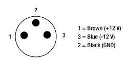
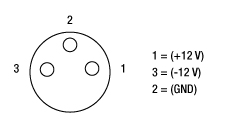
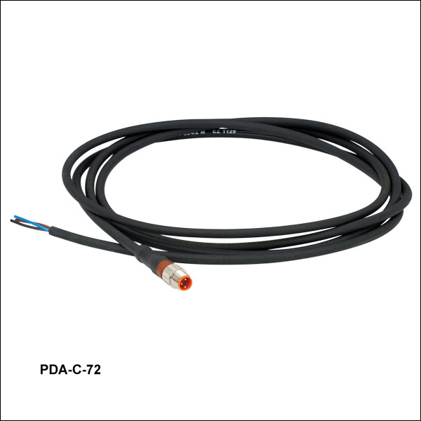
The PDA-C-72 power cord is offered for the PDA line of amplified photodetectors when using with a power supply other than the one included with the detector. The cord has tinned leads on one end and a PDA-compatible 3-pin connector on the other end. It can be used to power the PDA series of amplified photodetectors with any power supply that provides a DC voltage. The pin descriptions are shown to the right.

 Zoom
Zoom
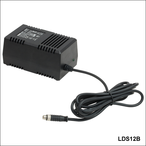
- Replacement Power Supply for the PDA and PDF Amplified Photodetectors Sold Above
- ±12 VDC Power Output
- Current Limit Enabling Short Circuit and Overload Protection
- On/Off Switch with LED Indicator
- Switchable AC Input Voltage (100, 120, or 230 VAC)
- 2 m (6.6 ft) Cable with LUMBERG RSMV3 Male Connector
- UL and CE Compliant
The LDS12B ±12 VDC Regulated Linear Power Supply is intended as a replacement for the supply that comes with our PDA and PDF line of amplified photodetectors sold on this page. The cord has three pins: one for ground, one for +12 V, and one for -12 V (see diagram above). A region-specific power cord is shipped with the LDS12B power supply based on your location. This power supply can also be used with the PDB series of balanced photodetectors, PMM series of photomultiplier modules,APD series of avalanche photodetectors, and the FSAC autocorrelator for femtosecond lasers.
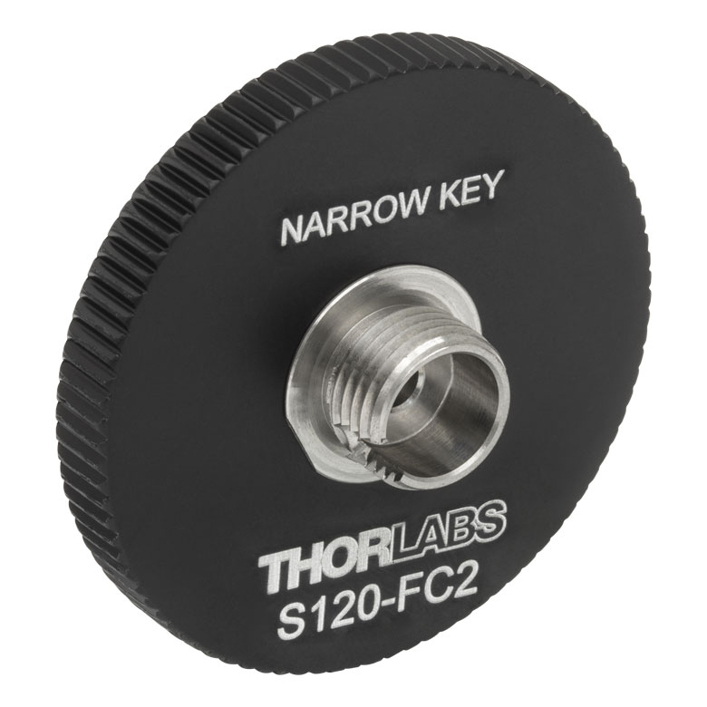
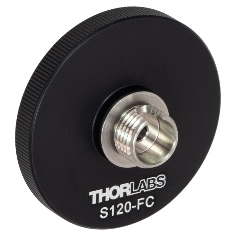
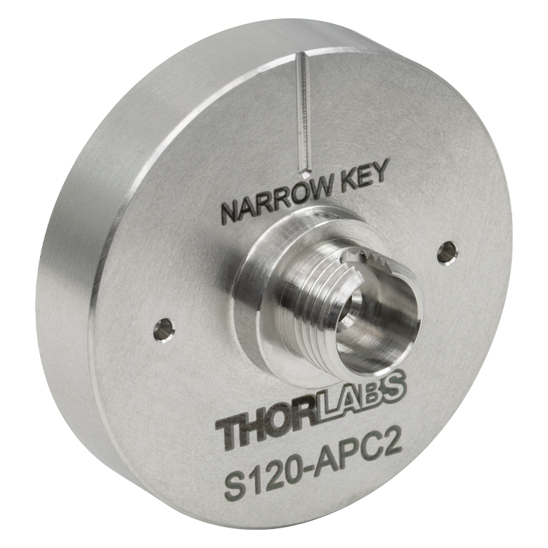
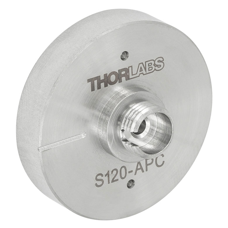
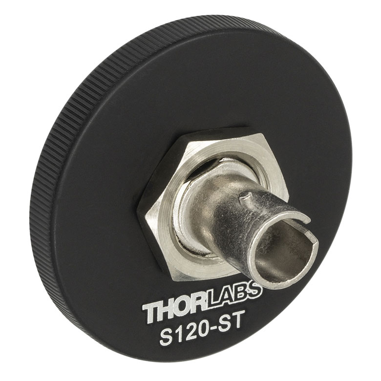
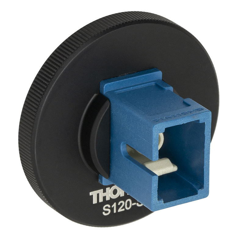
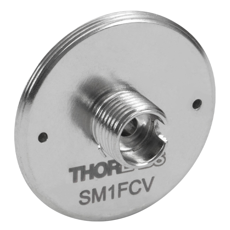
- FC/PC (Narrow or Wide Key), FC/APC (Narrow Key or Wide Key), SMA, ST®*/PC, SC/PC, LC/PC, or Ø2.5 mm Ferrule Receptacles
- Light-Tight Construction When Used with SM1 Lens Tubes
- Compatible with Many of Our Photodiode Power Sensors
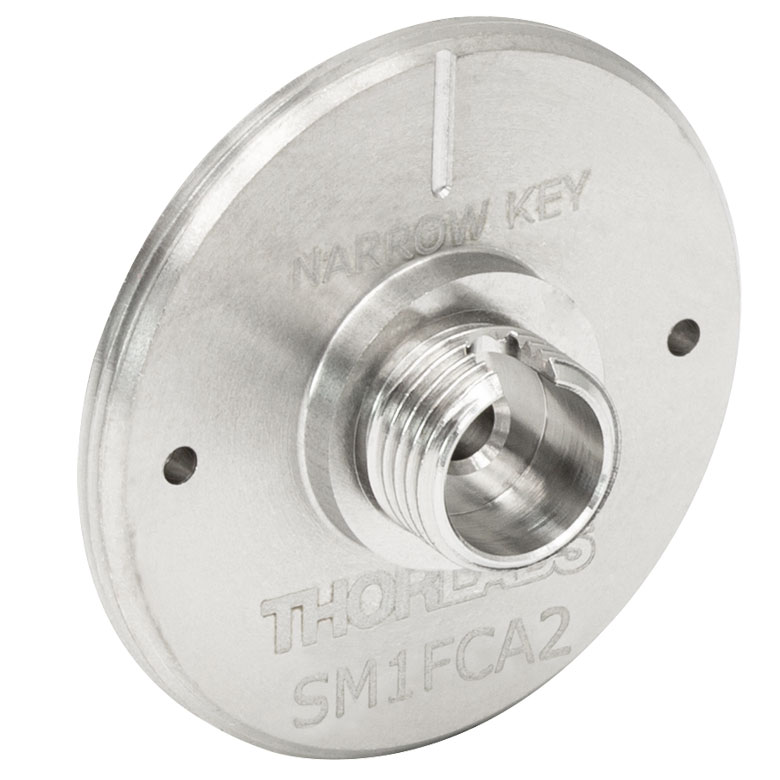
Note: The APC adapters have two dimples in the front surface that allow them to be tightened with the SPW909 or SPW801 spanner wrench. The dimples do not go all the way through the disk so that the adapter can be used in light-tight applications when paired with SM1 lens tubes.
FC/PC and FC/APC adapters are available with either narrow (2.0 mm) or wide (2.2 mm) key connectors; for more details on narrow versus wide key connectors, please see our Intro to Fiber tutorial.
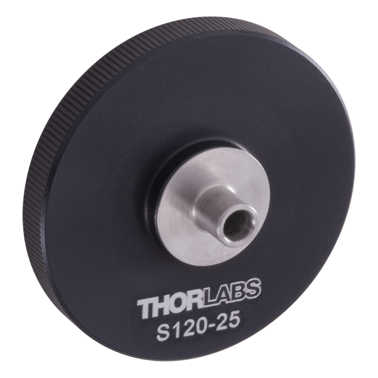
The S120-25 ferrule adapter is designed without a locking connector mechanism and accepts fiber patch cables with Ø2.5 mm ferrules for quick measurements with photodetectors or power sensors.
| Item # | S120-FC2a | S120-FCa | S120-APC2b | S120-APCb | S120-SMA | S120-ST | S120-SC | S120-LC | S120-25a |
|---|---|---|---|---|---|---|---|---|---|
| Adapter Image (Click the Image to Enlarge) |
 |
 |
 |
 |
 |
 |
 |
 |
 |
| Fiber Connector Type | FC/PC, 2.0 mm Narrow Key |
FC/PC, 2.2 mm Wide Key |
FC/APC, 2.0 mm Narrow Key |
FC/APC 2.2 mm Wide Key |
SMA | ST/PC | SC/PCc | LC/PC | Ø2.5 mm Ferrule |
| Threading | Internal SM1 (1.035"-40) | ||||||||
*ST® is a registered trademark of Lucent Technologies, Inc.
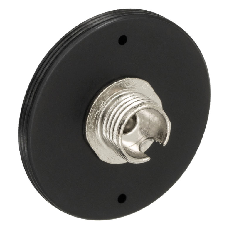
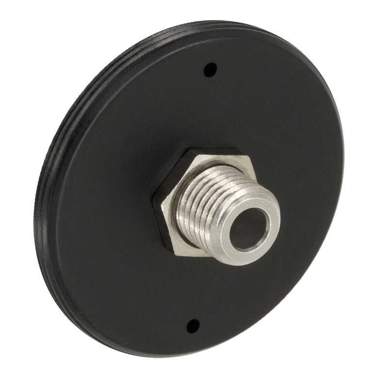
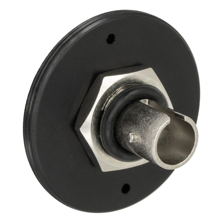
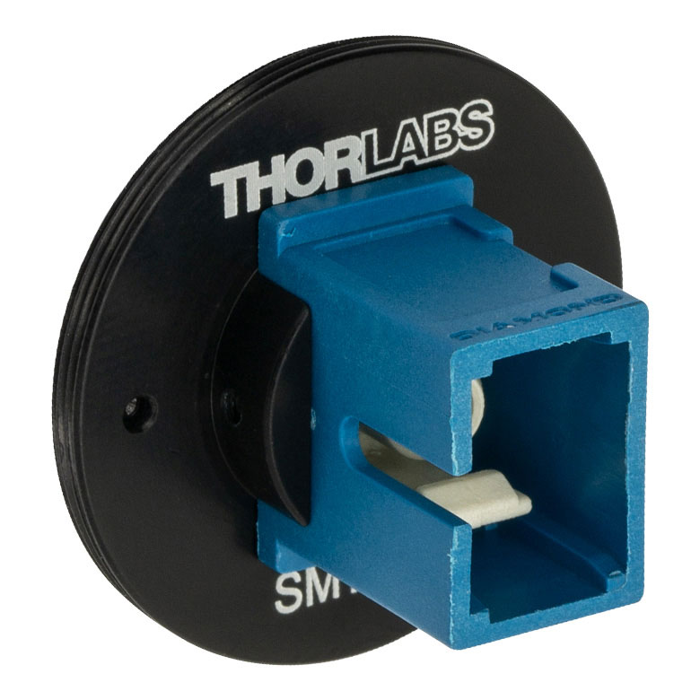
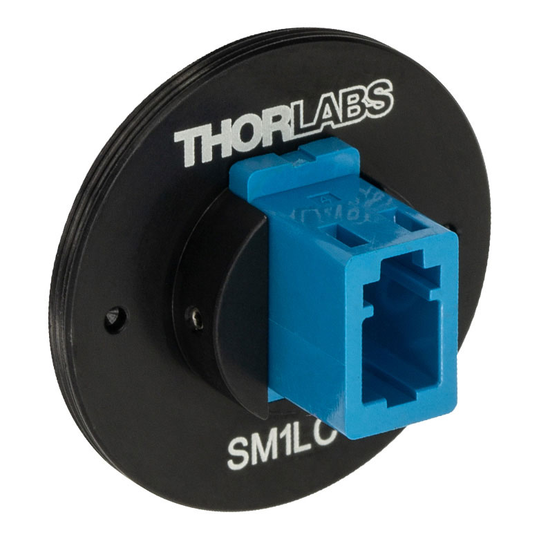
- FC/PC (Narrow or Wide Key), FC/APC (Narrow or Wide Key), SMA, ST®*/PC, SC/PC, or LC/PC Receptacles
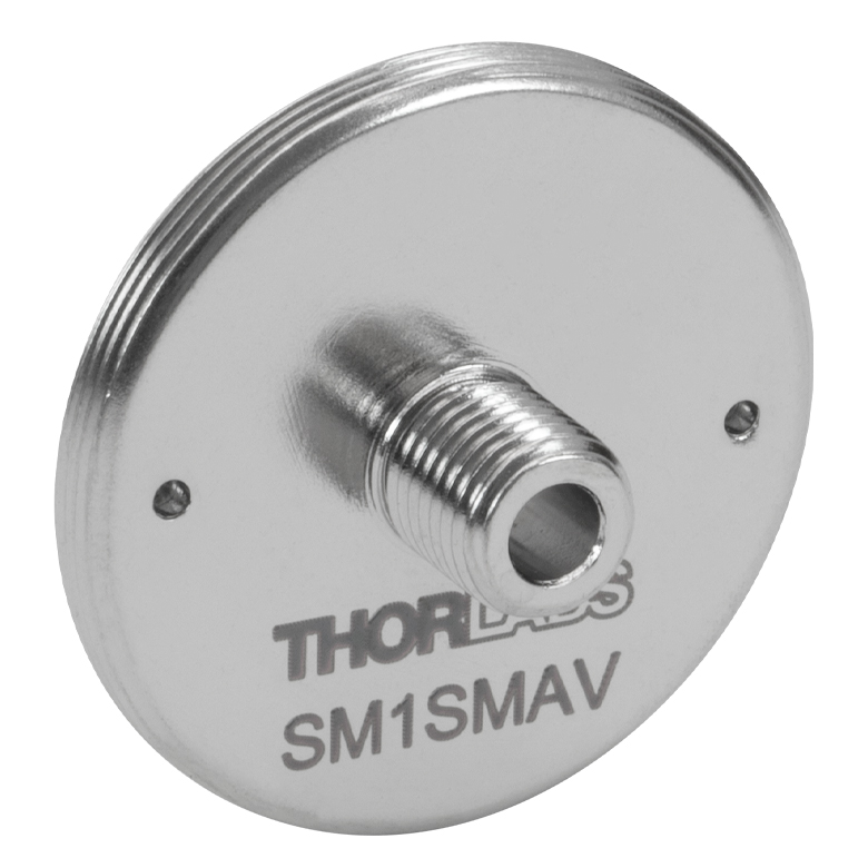
- Vacuum-Compatible Versions of FC/PC Wide-Key and SMA Receptacles Available
- Light-Tight When Used with SM1 Lens Tubes
- Compatible with Many of Our 30 mm Cage Plates and Photodetectors
Note: Each disk has four dimples, two in the front surface and two in the back surface, that allow it to be tightened from either side with the SPW909 or SPW801 spanner wrench. The dimples do not go all the way through the disk so that the adapters can be used in light-tight applications when paired with SM1 lens tubes. Once the adapter is at the desired position, use an SM1RR retaining ring to secure it in place.
FC/PC and FC/APC adapters are available with either narrow (2.0 mm) or wide (2.2 mm) key connectors; for more details on narrow versus wide key connectors, please see our Intro to Fiber tutorial.
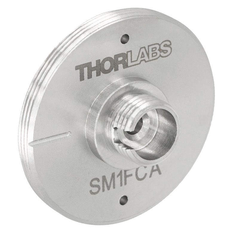
| Item # | SM1FC2 | SM1FC | SM1FCV | SM1FCA2a | SM1FCAa | SM1SMA | SM1SMAV | SM1ST | SM1SC1b | SM1LCb |
|---|---|---|---|---|---|---|---|---|---|---|
| Adapter Image (Click the Image to Enlarge) |
 |
 |
 |
 |
 |
 |
 |
 |
 |
 |
| Connector Type | FC/PC, 2.0 mm Narrow Key |
FC/PC, 2.2 mm Wide Key |
FC/PC, 2.2 mm Wide Key |
FC/APC, 2.0 mm Narrow Key |
FC/APC, 2.2 mm Wide Key |
SMA | SMA | ST/PC | SC/PCc | LC/PC |
| Vacuum Compatibility | - | >10-10 Torr | - | >10-10 Torr | - | |||||
| Threading | External SM1 (1.035"-40) | |||||||||
*ST® is a registered trademark of Lucent Technologies, Inc.