 Products Home
Shearing Interferometers
- Test Collimation of Coherent Sources
- Options for Beam Diameters from 1 to 50 mm
- Additional Shear Plates Available
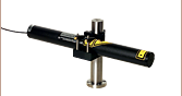
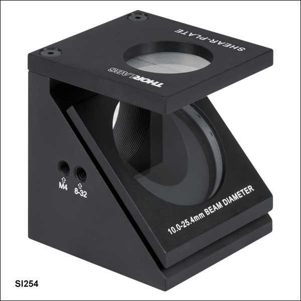
SI254
Shearing Interferometer with a 10 - 25.4 mm Beam Diameter Shear Plate
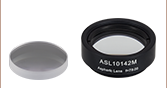
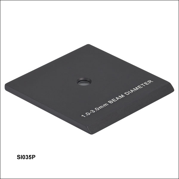
SI035P
Shear Plate,
1 - 3 mm Beam Diameter
Application Idea
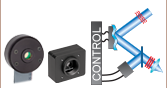
SI050 Interferometer with SICP Cage System Adapter, 30 mm Cage Components, and SM1 Lens Tube


Please Wait
Click for Details
Cross-Section of a Shearing Interferometer with Optional SICP 30 mm Cage System Adapter
Features
- Qualitative Collimation Testers for Coherent Beams
- Options for Beam Diameters from 1 mm to 50 mm
- <10% Beam Pick-Off
- Magnetically Coupled Kinematic Design to Quickly Interchange Shear Plates
- Imperial and Metric Threaded Mounting Holes
- 30 mm Cage System Compatible at Exit Port (Except Item # SI500)
- Replacement Shear Plates Offered Below
- Accessories Offered Separately Below (Not Compatible with Item # SI500)
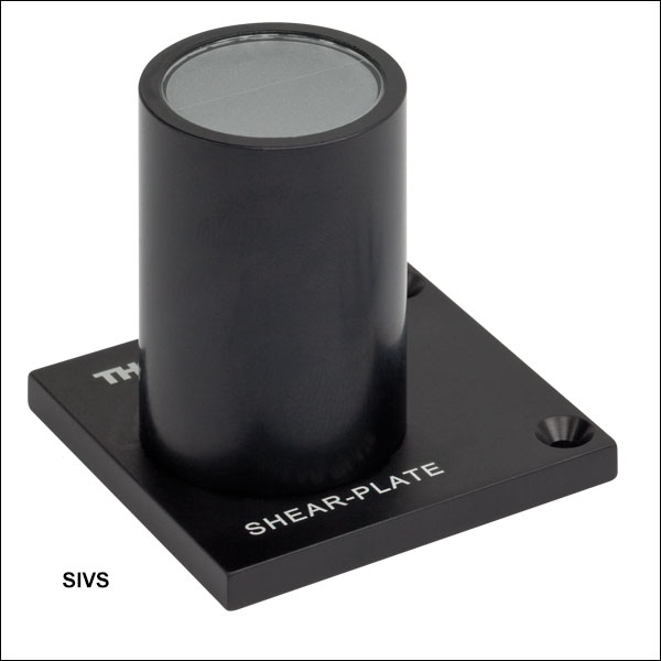
- SIVS Magnified Viewing Screen for Ø1 mm - Ø10 mm Beams
- SITST Mounting Plate with SM1 (1.035"-40) Internal Threads
- SICP and SICPSM1 Adapters for Input 30 mm Cage System Compatibility
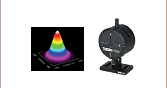
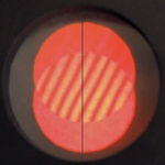
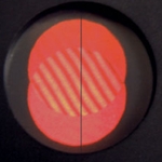
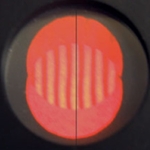
Thorlabs' Shearing Interferometers are designed to qualitatively test the collimation of a coherent beam of light. They provide a quick method to aid in the alignment of a collimating lens. The shearing interferometers consist of a wedged optical flat mounted at 45° to the incident beam. The reflection from both the front and the back surfaces of the optical flat overlap on a diffuser plate on the top of the device. A ruled reference on the diffuser plate indicates whether the incident beam is collimated. As shown in the image to the middle right, if the fringes are parallel to the line, the beam is collimated, and if they are rotated with respect to the ruled line, the beam is either diverging of converging.
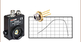
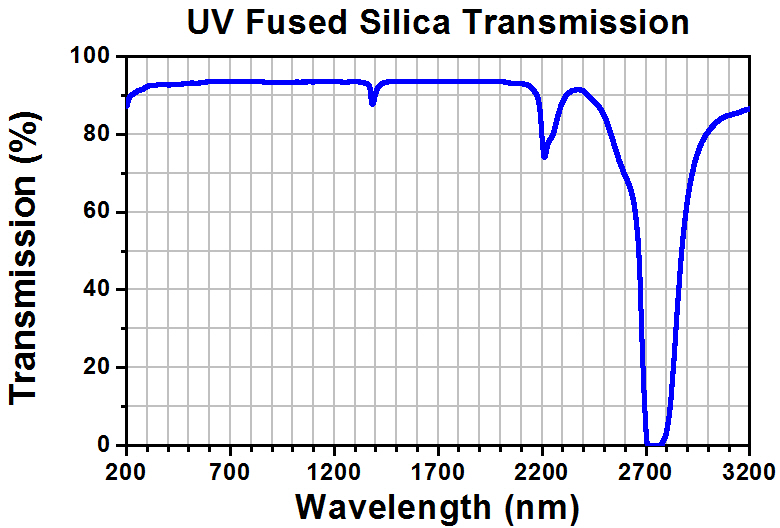
The wedged optical flat is made of uncoated UV fused silica, which has a transmission range from 185 nm - 2.1 µm. For use with IR light, an IR viewer is necessary to view the fringes on the diffuser plate. The wedge angle for each plate size is optimized for the range of the acceptable beam sizes indicated on the shear plate; see the Specs tab for details. Since the light is incident on the plate at a 45° angle, the intensity of the fringe pattern is dependent on the polarization of the light. Maximum intensity will occur when the polarization is perpendicular to the plane of incidence.
Usage Guidelines
This technique requires light with sufficient coherence, low wavefront aberrations, and a shear plate thickness compatible with the beam diameter. The interferometer also needs to be used within the Rayleigh range of the collimated beam. Please see the video at the top right for more details on these limitations.
To observe interference fringes, the coherence length of the incident light must be longer than the change in optical path length caused by the shear plate being used. See the Specs tab for the approximate change in optical path length, ΔOPL, for each shear plate offered here. Broadband sources, such as Superluminescent Diodes (SLDs) and LEDs, will not create interference fringes due to their low coherence lengths.
In addition to the degree of collimation, the fringes will also be sensitive to spherical aberration, coma, and astigmatism. Aberrations will result in fringes that are no longer straight, which makes it difficult to tell whether the fringes are aligned with the reference line. For quantitative information on wavefront errors, we recommend a Shack-Hartmann Wavefront Sensor or similar device.
For fringes to be clearly visible, the incident collimated beam diameter must be matched to the shear plate used. The shear plates sold on this page support incident beam diameters from 1 mm to 50 mm. We recommend the additional SIVS Magnified Viewing Screen for beam diameters from 1 mm to 10 mm.
The distance over which a beam is collimated is never infinite, and so the device should be located within approximately one Rayleigh range of the collimated beam's waist. For more information on collimation and calculating the Rayleigh range for your application, please see our Collimated Light Insight.
Construction
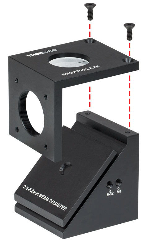
Each shearing interferometer comes in a case as a set of three pieces: a base, a plate with the wedged optical flat, and a plate with the diffuser viewing screen. To set up the interferometer, attach the viewing screen plate to the base using the included cap screws and hex key. The shear plate is held in place magnetically, allowing it to be easily swapped out for a plate with a different wedged optical flat.
Behind the wedged optical flat, a hole is bored through the base to allow the transmitted beam to pass through the optical flat unimpeded. Please note, the output angle and position will be affected by the wedge angle and thickness of the shear plate used. For all models except the SI500 interferometer, this output hole has internal SM1 (1.035"-40) threads and has four 4-40 tapped holes around it for integration into our 30 mm Cage System. The base is constructed from anodized aluminum and features tapped holes for mounting to Ø1/2" posts. The cross-sectional view to the right illustrates how the shearing interferometer is constructed as well as the laser beam's propagation path. This view includes an optional SICP adapter for mounting to a 30 mm cage system from the front of the interferometer.
| Item # | Wedge Angle |
Diameter | Diameter Tolerance | Thickness | Thickness Tolerance | Approximate ΔOPLa |
|---|---|---|---|---|---|---|
| SI035P | 117 arcsec | 7.94 mm | +0/-0.25 mm | 0.75 mm | ±0.25 mm | 1.9 mm |
| SI050P | 83 arcsec | 12.7 mm | +0/-0.25 mm | 1.30 mm | ±0.25 mm | 3.3 mm |
| SI100P | 40 arcsec | 15.60 mm | +0/-0.25 mm | 2.60 mmb | ±0.25 mm | 6.6 mm |
| SI254P | 18 arcsec | 38.00 mm | +0/-0.25 mm | 6.35 mmb | ±0.25 mm | 16.2 mm |
| SI500P | 10 arcsec | 78.00 mm | +0/-0.25 mm | 13.00 mmb | ±0.25 mm | 33.1 mm |
| Item # | Included Platea |
Beam Diameter for Included Plateb |
Compatible Plates | Compatible Accessories |
Threaded Mounting Holes |
Dimensions (L x W x H) |
|---|---|---|---|---|---|---|
| SI035 | SI035P | 1 - 3 mm | SI035P, SI050P, SI100P, and SI254P | SIVS, SITST, SICP, SICPSM1 | 8-32 and M4 | 50.8 mm x 48.3 mm x 55.9 mm |
| SI050 | SI050P | 2.5 - 5 mm | ||||
| SI100 | SI100P | 5 - 10 mm | ||||
| SI254 | SI254P | 10 - 25.4 mm | SIVSc, SICP, SICPSM1 | |||
| SI500 | SI500P | 25.4 - 50 mm | SI500P | None Available | 1/4"-20 and M6 | 116.8 mm x 133.4 mm x 134.6 mm |
Click to Enlarge
Above is the transmission curve for UVFS, with light incident normal to the surface. The data shown is for a 1 mm thick, uncoated sample and includes surface reflections.
| Posted Comments: | |
Dimitre Ouzounov
(posted 2024-03-13 04:20:39.43) Hi,
do you offer modification of the shearing interferometer for collimation of femtosecond pulse beams? Say, around 100 fs, because of the larger bandwidth, I guess some form of compensation in one arm is needed. Do you offer anything for such purposes?
thanks,
dimitre ksosnowski
(posted 2024-03-28 04:37:37.0) Hello Dimitre, thanks for reaching out to Thorlabs. Unfortunately we are not able to offer a shearing plate like this currently. I have reached out directly to discuss your application in further detail. user
(posted 2024-03-05 08:08:22.737) Hello, is it possible to get a SI035P shear plate with a diameter larger then 7.94 mm? cdolbashian
(posted 2024-03-15 04:09:36.0) Thank you for reaching out to us with this inquiry! I have contacted you directly to learn a bit about your application, and suggest alternative stock parts. For custom requests, please feel free to email Techsales@thorlabs.com. FURKAN Çelik
(posted 2024-01-24 21:27:34.963) ı have a parobolic mirror with a diameter of 203 mm and focal length of 1016 mm.I want to use shearing interferometer to make precise focal lenght measurements for this mirror.Is this interferometer suitable for my purpose? ksosnowski
(posted 2024-01-29 05:57:04.0) Hello Furkan, thanks for reaching out to Thorlabs. Whether the shearing plate produces fringes depends on the coherence length of the light source, which must be sufficiently greater than the optical path length difference of the system to obtain an interference pattern. We list the approximate OPL difference for each shearing plate in our Specs tab. Optics with high surface irregularity or highly multimode systems may cause some irregularity in the output fringes if additional path length differences are induced. The wedge of our shear plates is intended to provide a linear fringe pattern parallel to the engraved line when optimally collimated. I have reached out directily to discuss your application in further detail. Lin Xin
(posted 2023-12-21 17:01:38.153) Is there a way for me to order the base of SI500 without a plate?
Thank you!
Best,
Dr. Lin Xin
Postdoctoral Scholar
Stanford University Peter Meinhold
(posted 2023-06-01 13:03:05.293) I'm working with a 0.6 mm diameter beam. Will the SIO35 just be difficult to use, or will it not work at all since the beams won't overlap? I'd rather not use a beam expander since that will add uncertainty to the collimation I'm trying to measure. cdolbashian
(posted 2023-06-02 03:24:38.0) Thank you for reaching out to us with this inquiry. Due to the geometry of the shearing plate, and the dimensional parameters therein, it seems like the minimal beam separation would be on the order of ~0.5-0.6mm, and you would likely get little to no overlap between beams with diameter 0.6mm. Lutz Kellan
(posted 2023-05-03 09:57:22.863) I'm considering purchasing the SI254.
We are considering this product for our 355nm laser optics focus setting. In the previous answer 355nm light is an area that can be seen with the naked eye. So, because it's dangerous, we have to use the camera system. it right?
Do you have any experience in applying SI254 Product Camera Viewer? If you suggest, we will consider purchasing additional accessories. ksosnowski
(posted 2023-06-13 11:38:36.0) Hello Lutz, thanks for reaching out to Thorlabs. Apologies for any confusion however the previous feedback had a typo which has been updated to reflect that 355nm is not visible to the naked eye. UV is still however harmful to living tissues and fluorescent viewing materials are often used to visualize this. Potentially our ADF4 may work for viewing if the optic power is high enough. Otherwise the interferometric effects are still occurring even though the human eye can't see this directly. I have reached out directly to discuss this application further. Daiki Matsubayashi
(posted 2022-09-16 06:08:36.903) I would like to use this item at 355nm wavelength. Is it possible? ksosnowski
(posted 2022-09-22 04:24:23.0) Hello Daiki, thanks for reaching out to Thorlabs. The shearing interferometers use a UVFS substrate which maintains transmission performance at 355nm. The optical path length and resulting fringe spacing will change slightly due to the different index of refraction, though with a greater coherence length this won't be an issue. 355nm is not visible to the naked eye, so this would require an external viewer like a camera or something sensitive to this UV wavelength. Asaf Toprakci
(posted 2022-08-16 08:13:39.56) Hello, I'm using this product in my setup, and it provides me with great feedback on the collimation of my light beam. The only question that I have is this. If one sees an interferences pattern consisting of some curves but not straight lines, does this give any information about the collimation of the light beam? Or does this means the light has some aberrations? ksosnowski
(posted 2022-08-23 01:18:41.0) Hello Asaf, thanks for reaching out to Thorlabs. Some bending in the fringes can be a result of spherical aberration in the input beam profile. I've reached out directly to discuss your application in more detail. chris brophy
(posted 2022-05-15 04:44:03.287) On the shear plate, how well is the indicator line oriented (clocked) wrt the wedge direction? Is it to better than 1 min of arc? ksosnowski
(posted 2022-05-18 02:52:16.0) Hello Chris, thanks for reaching out to us. The indicator is aligned visually so we do not have a specification for this, however we would realistically expect this to be on the order of degrees rather than arc-minutes. Jennifer Michels
(posted 2021-09-27 13:32:02.153) Do you have an estimated accuracy for the system with the 83 arcsecond wedge? Specifically, I am thinking that if the reticle rotation is not perfectly aligned to the wedge direction, there will be an absolute error. Can I assume that the reticle rotation is accurate to within ±1 degree? Thank you! YLohia
(posted 2021-10-15 11:18:34.0) Thank you for contacting Thorlabs. Unfortunately, we don’t have a value for the accuracy of the system. For the smaller plates, there may be a +/- 5 degree rotational accuracy, but that is only an estimate. We expect higher accuracies on the larger diameter plates. Marshall Scott
(posted 2021-07-28 08:32:06.457) This is one of my favorite tools. You should make a tutorial for how to use these things.
https://www.reddit.com/r/Optics/comments/ot21oa/shear_interferometer_measurement_method_need_help/ YLohia
(posted 2021-07-29 02:10:49.0) Hello, thank you for your feedback! We're happy to hear that these are one of your favorite photonics tools. We will consider offering an "Insight" on Shearing Interferometers in the future. user
(posted 2021-07-07 17:14:16.64) 你好,我们很早就买了一套SI100,现在用来检测532nm的激光时,看不到条纹,请求帮助。 YLohia
(posted 2021-07-07 02:58:02.0) Hello, an applications engineer from our team in China (techsupport-cn@thorlabs.com) will discuss this directly with you. user
(posted 2021-04-27 09:34:08.863) It would be super helpful if you added a resource tab to this product line with a series of images showing the effects of different aberrations on the observed interference fringes. Seeing how astigmatism, coma, spherical, or a few common combinations of aberrations in addition to simple de-focus would really enhance the usability for users and ability to troubleshoot problems in their system. Answering a few of the other questions users have already posted below would also be helpful, such as: a GIF showing how decreased coherence washes out the contrast of the fringes, also better explanations with a diagram or two of how the collimation may look slightly different between shear plates if your beam is a cutoff diameter that could be used with 2 different plates (10mm diameter for example) and how choosing the right size actually impacts your measurement. I always appreciate your excellent resources and think this could be a great addition. Thank you for your consideration! tcampbell
(posted 2021-04-27 05:01:32.0) Hello, thank you for contacting Thorlabs. We greatly appreciate your suggestion to add this resource to our presentation. We will look into creating a tutorial for these interferometers shortly. Melissa G
(posted 2021-04-26 00:59:34.317) Thank you for the helpful product!
I have many questions, but I am grateful for answers to any of them!
If I am able to expand my beam to an arbitrary size by different FL lenses, is there one I should prefer for the most sensitive characterization of collimation? Does the use of an iris in a large beam affect performance of the shearing interferometer? I often get a cleaner image if I over-fill the aperture, does that make sense to you? Do dirty plates affect the shape of the interferogram; if so, how do you suggest I clean them? I can find more information on non-wedge shearing interferometers; are there any educational/instructional sources you recommend?
Thank you for your time and for any help you are able to provide. YLohia
(posted 2021-05-06 03:35:53.0) Since this is a qualitative way of evaluating the collimation level by observing fringes, the "most sensitive characterization" will be what the user can see the easiest-- so using the largest beam size possible. Please note that the larger SI's have thicker optics, so the coherence length of your source should also be longer. Yes, dirty plates can certainly affect the quality of the interferogram-- we suggest cleaning them with isopropyl alcohol (https://www.thorlabs.com/newgrouppage9.cfm?objectgroup_id=9025). user
(posted 2021-04-20 13:58:01.87) Is it possible to buy a kit that contains the holder, the diffuse screen, and all 5 shear plates? YLohia
(posted 2021-04-21 02:29:11.0) Thank you for contacting Thorlabs. Unfortunately, such a kit is not available for sale. At the moment, you would have to procure all the components separately. We will consider adding such a kit to the catalog in the future. 跃 王
(posted 2020-12-28 21:07:12.537) 您好,
我最近购买了这款干涉仪器去调节光束准直(diameter=30mm);但是发现干涉条纹并不是完全平行,中间的条纹较为扭曲;不知道是什么原因?希望你们可以提供一些帮助;
感谢!
王跃 YLohia
(posted 2020-12-29 10:46:46.0) Hello, thank you for contacting Thorlabs. An applications engineer from our team in China (techsupport-cn@thorlabs.com) will reach out to you directly to discuss this. user
(posted 2020-07-21 01:34:28.26) Hi there, any concern while using the shear plate? I'm working on a 532nm beam. I can see the beam is diverging while hitting on the wall while the shear interferometer tell me it is collimated. Yang Xu
(posted 2020-07-21 00:45:18.123) Hi Thorlabs,
I'm using your shear interferometer as a reference to collimate my laser beam and I found several questions/problems listed below:
1. While I'm trying to collimate my beam (diameter~25mm), I found that the collimating point(parallel line) telling by SI254 is quite different from that telling by SI100. I'm wondering why that would happen? Which one I should rely on?
2. In some cases, interference patterns shown on the viewing window are blended (not straight). Is it possible that Thorlabs can provide a detailed instruction on how to use the Shear interferometer and what different pattern means?
Many thanks! asundararaj
(posted 2020-08-10 09:44:11.0) Thank you for contacting Thorlabs. Differences in the patterns can be attributed to coherence length of laser, thickness of shear plate, and more importantly wedge angle. The choice of the shear plate should be based on the beam size; for a 25 mm beam, the SI254 should be used.
The fringe quality observed on the shearing interferometer depends on the beam quality which corresponds to the choice of lens used to collimate your beam. I have reached out to you to discuss this further. Christian Schmidt
(posted 2020-06-17 11:35:15.09) Hello. Is it possible to geht the interference plates, without the glas or with unwedged glasses? nbayconich
(posted 2020-06-17 02:00:18.0) Thank you for contacting Thorlabs, we can provide the shear plates or diffuser plates without optics. I will reach out to you directly with more information. Christian Oggenfuss
(posted 2020-05-04 14:48:49.46) Is it possible to measure the incident angle of the beam with this interferometer? Will the distance between the fringes change? asundararaj
(posted 2020-05-21 11:52:37.0) Thank you for contacting Thorlabs. It would not be possible to measure the incident angle of a beam with a shearing interferometers. The shearing interferometers offer a qualitative test for the collimation of the beam. The AOI of a beam can be determined/tracked by reflecting a beam and observing beam translations on a position sensing detector.I will reach out to you directly about your application. Simon BECKER
(posted 2020-02-12 10:48:36.683) Hello,
I'im using the shear interferometer for set the good colimation of my laser in ordrer to make digital Holography.
Previously I'have use an MCLS1-520 diode in a 4-channel fiber-coupled laser and I was able to see the fringe.
Everything was allright.
Since I use a 660nm single mode laser LP660-SF50 coupled with a PAF2-A4B fiber collimator, I'm not able to see the fringe.
Because the fiber is 5µm diameter core single mode, I assume that the wave is spatialy filtered.
Can you help me to understand why the interferometer doesn't work with my 660nm laser and if I have a way to make it work.
Thank you
Best regards YLohia
(posted 2020-02-17 11:49:28.0) Hello Simon, thank you for contacting Thorlabs. The reason you are not seeing interference fringes on your shearing interferometer is due to the short coherence length of the LP660-SF50, which is a Fabry-Perot diode with multiple longitudinal modes. The coherence length of this particular diode is on the order of <1 mm (depends on temperature and current setpoint). The thinnest shear plate we offer has an approximate optical path length of around 2.5 mm @ 632 nm. Therefore, the beam from this diode will no longer be coherent over a full round-trip within the shear plate. We confirmed this with an in-house test with this diode and also confirmed functional performance of the shearing interferometer using a long coherence length source (HeNe laser). You should be able to see interference fringes with a single frequency laser such as the L670VH1. SB Wu
(posted 2019-11-05 03:27:35.187) To Whom It May Concern,
Are Shearing Interferometers also fit for noncoherent light, say, LED, Xe lamp, etc? nbayconich
(posted 2019-11-05 12:54:43.0) Thank you for contacting Thorlabs. The shearing inteferometers would not be suitable for an incoherent light source such as and LED or Xenon Lamp. In order to create interference fringes a source with a coherence length longer than the change in optical path length must be used with these shearing interferometers. melch0r
(posted 2019-01-22 08:48:31.3) Hello,
i am wirting my bachleor thesis about the digital optical twin and how it could be measured or monitored. I cant find any specs regarding accuracy or time to measure. Can you help me out?
thanks YLohia
(posted 2019-01-24 10:26:45.0) Hello, thank you for contacting Thorlabs. I have reach out to you to gather more information about your application. e.lopez
(posted 2018-09-07 12:27:17.58) Hello, we have a 785nm and a 1064nm CW laser.
If we buy the shearing interferometer, do we need extra items to see the fringes?
Thank you in advance. Eneko nbayconich
(posted 2018-09-07 02:14:47.0) Thank you for contacting Thorlabs. For your 1064nm source you will need to have an IR camera in order to see the fringes created by the shearing interferometer. For your 785nm you may not need an IR camera as this can be faintly visible but will be dependent on the intensity of the 785nm source and the individual observing the interference pattern. laric.bobzien
(posted 2018-03-15 10:20:18.757) I need the holder, without the shear plate. (I already have multiple shear plates, but only one holder.) Would you sell one separately? If so, at what cost? nbayconich
(posted 2018-03-15 02:37:22.0) Thank you for contacting Thorlabs. Yes we can provide the shear plate holders separately. I will reach out to you directly with a quote. gspaldin
(posted 2017-10-16 14:17:23.69) I need the holder, without the shear plate. (I already have multiple shear plates, but only one holder.) Would you sell one separately? If so, at what cost? (This is for teaching purposes.) nbayconich
(posted 2017-10-18 03:40:44.0) Thank you for contacting Thorlabs. We can provide the holder for you. I will contact you directly for a quote. yev
(posted 2017-04-28 05:21:59.88) Dear Sirs!
We need to collimate laser channel of rangefinder
905nM high power pulse laser diode as source.
Please how we can see the fringes on the screen? tfrisch
(posted 2017-05-02 12:21:40.0) Hello, thank you for contacting Thorlabs. In the past, customers have used IR cameras to view the diffuse plate. I will reach out to you directly about your application. user
(posted 2016-11-28 15:25:18.67) The kinematics are not very good. This device needs stronger magnets. tfrisch
(posted 2016-11-29 01:30:32.0) Hello, thank you for contacting Thorlabs. I'm sorry you are having trouble with this product. If you reach out to us at TechSupport@Thorlabs.com, we can discuss how it is mounted and possible solutions. I look forward to hearing from you. parksj003
(posted 2016-11-18 08:15:31.183) Hello,
Shearing interferometer can work for the femtosecond laser (700-1000 nm)?
If so, IR camera with some focusing elemets are only option to see the fringes?
Best,
Seongjun tfrisch
(posted 2016-11-28 04:01:29.0) Hello, Thank you for contacting Thorlabs. I have several concerns that are application specific. I will reach out to you directly. luoyukun4580
(posted 2016-11-09 17:24:06.33) Dear sir or madam, I am using the SI254P to check the collimation of our laser beam with a diameter about 20mm at 780nm. Although we adjust the collimator to achieve a desired fringe that indicates a collimated light, we can see an obvious foucs of our laser beam. And if we adjust the laser to be roughly collimated through naked eye, the fringe is just not parallel to the reference line?
Should there be some proper expalnations to the phenomenon and which collimation criterion should we refer to? tfrisch
(posted 2016-11-14 08:34:46.0) Hello, thank you for contacting Thorlabs. I have reached out to you directly about your application. tzu-lun.wang
(posted 2016-03-09 09:49:09.057) Dear Sir or Madam,
I am using Throlab's sheer plate to test our Ti:Sapphire pulse laser. My problem is we can't see any fringes now.
We were able to see the fringe patterns, but the contrast is very low, and sometimes it even disappeared. But last week the specialist from the laser company (Spectra Physics, Tsunami) come here to optimize our laser, and after that we cannot see fringes anymore, and I always measured the laser under continues wave mode. What the specialist did is just simply align the laser by adjusting and cleaning the mirror inside the laser cavity. Because our light source is a laser with continues wave, so the coherent length should not be a problem
So here I would like to ask that do you have idea about the low contrast of fringe patterns, and also why the fringe patterns are not able to be detected after we optimizing the laser? Thank you very much! besembeson
(posted 2016-03-10 03:02:06.0) Response from Bweh at Thorlabs USA: This should be related to the coherence length of your laser compared to the change in optical path length. The fringe contrast decreases as your coherence length approaches a few multiples of the change in OPL. We will contact you to look into your laser properties further. achmyro
(posted 2015-10-30 19:09:00.587) Is it possible to use SICPSM1 in combination with VRC2SM1 for checking collimation of IR beams?
Is VRC2SM1 transparent enough to see the interference fringes? I guess you can check this easily in your lab. besembeson
(posted 2015-11-04 05:44:18.0) Response from Bweh at Thorlabs USA: The VRC2SM1 will not work since it is not transparent. It is made from a durable plastic and has a photosensitive region adhered to the front surface. The VRC5 can be transparent as it has clear plastic on both sides of the photosensitive material. When the VRC5 is used in a darkened room with a sufficiently high power IR source, the fluorescence from the activated photosensitive region can be seen through the back of the card but the fringe contrast to determine collimation will be too poor to be usable. If you have an IR viewing camera, you may consider that. daniel.najer
(posted 2015-09-14 13:14:38.763) Dear Sir or Madam, would it be possible to use an SI035 Shearing Interferometer at a wavelength of 950 nm? What about observing the interference pattern with an infrared viewer? Or are there any other options, such as a fluorescent diffuser plate? Best regards! jlow
(posted 2015-09-23 09:38:59.0) Response from Jeremy at Thorlabs: The shearing interferometer can be used at 950nm but you do need a way to see the inteference fringes such as an IR viewer. We do not currently offer the fluorescent plates but this is something that we are looking into. dverhaart
(posted 2014-08-20 10:31:12.883) We use the device routinely to collimate ~ 7 mm (1/e2) diameter 355 nm laser beams. We normally use SI100, but have also used SI030, SI050 and SI254.
When comparing various devices (many SI100 and one each of the other ones) om a beam perfectly collimated with one device, we find the tilt angle of the pattern to vary in a +/-5 degree range, with an outlyer of almost 20 degree for the SI254.
This means that collimation state of the beam will depend on the device used.
What is Thorlabs spec for orientation accuracy of the wedge? For the instrument to be accurate it should be better than 1 degree! besembeson
(posted 2014-10-10 09:33:19.0) Response from Bweh at Thorlabs: Such a large variation is not an expected observation for these units. When we produce these parts we use a very well collimated visible source, a dedicated jig with the Zygo GPI to align the plates and in this setup, we don't have an orientation accuracy specification. The SI254 should be returned to us to test if we can reproduce this result since we don't expect this to be off by 20°. We can also check any of the other units that you would like to be returned. sh.han
(posted 2014-01-27 10:03:59.243) Dear Sir or Madame, can I use SI100 at 1550nm? If it is possible, please let me know other requirements. For example, do I need IR camera or something?
Thank you in advance. sgebhart
(posted 2014-01-23 11:25:13.353) I am trying to use the S100 to test collimation for a superluminescent diode centered at 830nm with a FWHM bandwidth of 18nm, roughly Gaussian spectrum, and 6mm beam diameter. Thus far, I have been unable to see any fringes, with our without the SIVS, with my NIR camera. I can see the overlapping spots, but there is no fringe pattern present within the overlapping region. Please let me know if you have any suggestions. Thanks! besembeson
(posted 2014-01-29 11:23:36.0) Response from Bweh E. at Thorlabs: Thanks for choosing Thorlabs. The reason you unable to see any fringes is because of your source. Superluminescent sources have high spatial coherence but their temporal coherence is very low. This means that they also have very short coherence lengths (typically well under 0.1mm). The contrast of the interference fringes decreases as the coherence length of the source approaches a few multiples of the optical path length change (?OPL) in the shearing interferometer . The SI100 has an ?OPL of 6.62mm (for 632.8nm laser or slightly less at 1550nm) meaning that any source with a coherence length less than this value will not produce interference fringes. muellenbroich
(posted 2013-11-07 16:24:06.537) One of the little metal balls that fixes the shear plate to the viewing cube has fallen off and disappeared forever more into the optical table. Is it possible to get a replacement?
Thanks! tcohen
(posted 2013-11-07 03:48:15.0) Response from Tim at Thorlabs: Thanks for bringing this to our attention. We’ll contact you with a replacement and check assembly (they should be permanently epoxied and difficult to displace). muellenbroich
(posted 2013-10-17 12:32:53.333) We just bought the SI035 but I cannot see any fringes. The laserbeam is about 1mm diameter, 445nm, p-polarised (Cobolt MLD™ diode laser) in combination with a ND filter (no3)because I tought eye saturation might be an issue. Can you help to troubleshoot? Would the magnifying accessory definitively help to see the fringes (if there are any)? Cheers! jlow
(posted 2013-10-17 08:58:00.0) Response from Jeremy at Thorlabs: The effective coherence length of the laser should be much larger than the optical path length difference (around 1.91mm for SI035) to get good fringe contrast. It can also be hard to see the fringes with a Ø1mm beam. We will get in contact with you directly to troubleshoot this. avle
(posted 2013-10-14 01:54:25.803) any suggestions for using the shearing interferometer for beam diameters less than 1mm?
would using a beam expander before the shearing interferometer work?
We regularly have beam diameters that are all centered around .5mm.
thanks! cdaly
(posted 2013-10-17 16:15:00.0) Response from Chris at Thorlabs: Thank you for using our feedback tool. The beam expander would be the way to improve the visibility. But you'll want to make sure that the beam expander is already well adjusted for your focal length so that the output beam is not giving you any false information about the collimation of the input beam. joseph.lawson
(posted 2013-07-15 18:22:25.623) Is it possible to get a replacement diffuser plate? tcohen
(posted 2013-07-16 20:04:00.0) Response from Tim at Thorlabs: Yes, we can supply this. We will contact you with a quote. tcohen
(posted 2013-01-02 09:47:00.0) Response from Tim at Thorlabs: Thank you for your request. We may be able to offer a modified SI035 with SIVS to suit your needs. There are manufacturing limits on the shear plate that will restrict the diameter from much smaller than 1mm. As you have not provided an email for us to contact you directly, please contact us at techsupport@thorlabs.com to discuss possible solutions for your beam diameter. user
(posted 2012-12-19 07:26:57.45) Are there plans to offer plates for beam diameters < 1 mm? rscholl
(posted 2012-12-05 11:52:00.0) A response from Ryan at Thorlabs: Thank you for contacting us. It sounds like the issue is regarding the contrast of the stripes or interference fringes. This suggests the coherence length is less than several times the optical path length difference of the interfered beams. We will contact you directly for more information. martin.vogel
(posted 2012-11-23 14:35:06.927) Hi, I have a strange observation using the SI100: With a blue laser @ 488nm, I see a nice patterns of stripes. With a yellow laser @ 580nm, I also see a stripe pattern, but it is overlaid with a bright spot of light. Any idea what could be the cause for this? Many thanks, Martin tcohen
(posted 2012-09-13 13:09:00.0) Response from Tim at Thorlabs: When using the SI100, we would expect to see about ~2.8mm at your wavelength. You will notice the wedge angle increases for smaller beam diameters to reduce the fringe spacing and be discernible in the visible wavelengths. As the fringe spacing is directly proportional to wavelength, it will be larger for 1.55um. Currently, we are working on NIR shearing interferometers to be able to be detected with the same convenience as our visible versions. ron.stahl
(posted 2012-09-07 14:29:54.0) What fringe spacing can I expect from a 1.55micron wavelength beam with the SI100? I found a formula that suggests that it would only be a few microns and I'm concerned that I won't be able to see this with my InGaAs camera. jjurado
(posted 2011-08-17 13:51:00.0) Response from Javier at Thorlabs to david.milne: The reason why different plates are offered for different ranges of beam diameters is that, in order to observe the interference pattern of a particular beam generated by the front and back surfaces of the shear plate, the wedge angle of the optic needs to be carefully chosen. Launching a large beam onto a small diameter shear plate (and vice versa) will cause the front and back surface beams to be misaligned, preventing the formation of the interference pattern. I will contact you directly for further support. david.milne
(posted 2011-08-17 15:19:02.0) Can you explain why you need different shear plates for different beam diameters? For instance if I use a large beam with the small diameter shear plate, will I still see fringes? If I use a small beam with a large diameter shear plate, will I still see fringes? jjurado
(posted 2011-08-02 13:47:00.0) Response from Javier at Thorlabs to dcasale: In order to view the fringe pattern generated by the interferometer at 1064nm, it would be necessary to place a translucent fluorescing material on top of (or in place of) the diffuser plate, or to use an IR viewer or camera. We currently do not carry these product, but I will contact you directly with some suggestions. dcasale
(posted 2011-08-01 14:17:19.0) What is recommended when viewing 1064nm lasers? Should the top plat be replaced with a fluorescing material, or can it be laid directly on top/below? jjurado
(posted 2011-05-04 15:00:00.0) Response from Javier at Thorlabs to Eric Le Moal: Thank you very much for contacting us. I will contact you directly to help you troubleshoot your application. eric.le-moal
(posted 2011-05-04 09:09:45.0) Dear Sir/Madam, the shearing interferometer shows no fringe contrast with our laser source that emits 6 ps pulses at 1064 nm (I use a IR camera to look at the shear plate). As 6 ps pulses are relatively short (1.8 mm in vacuum), I wonder if this is a time coherence issue. Could you please tell me what is the thickness of the shear plate itself? (namely the length difference between the two interfering paths)
Best regards,
Eric Le Moal jjurado
(posted 2011-02-24 14:44:00.0) Response from Javier at Thorlabs to Sebastian Jaeger: Thank you for contacting us. In order to integrate our shearing interferometers into our cage systems, it is necessary to use the SITST plate. The current design does not feature additional holes for the 30 mm cage system. user
(posted 2011-02-24 05:21:47.0) Dear Sir or Madame, is it possible to mount the shearing interferometer in front of an cage-system (e.g. a 30mm cage system) or do I need to go over a SM1 thread by using the SITST plate? Best regards, Sebastian Jäger Thorlabs
(posted 2010-09-14 08:58:33.0) Response from Javier at Thorlabs to Holger Fischer: we will contact you directly in order to troubleshoot your application. fischer
(posted 2010-09-09 07:31:12.0) Dear Madame or Sir, we have purchased a shearing interferometer (SI100) to determine the collimation of a laser beam. Unfortunately we are not able to see any fringes on the screen of the assembly. The laser beam is well adjusted at 45° to the shear plate with a diameter of about 6-8mm. Different lasers (pulsed and cw) at different wavelengths (780nm, 532nm and 648nm) did not show any result. Do you have any proposition for getting fringes or any contact to get more information on the shearing interferometers?
Best regards,
Holger Fischer apalmentieri
(posted 2010-02-02 13:58:56.0) A response from Adam at Thorlabs to Nick: The wedge angle for these interferometers are 117 arcsec(SI035), 83 Arcsec(SI050), and 40 Arcsec(SI100). nick
(posted 2010-02-02 13:23:52.0) Hello, Can you please tell me the wedge angle in the SI035, SI050, and SI100 plates? This is useful in determining fringes across the 500-2000nm range that might be utilized.
Thanks,
Nick Laurie
(posted 2009-04-06 16:21:18.0) Response from Laurie at Thorlabs to msones: Thank you for your interest in our shearing interferometers. Unfortunately, at this time, we do not have the appropriate measurement equipment necessary to determine the degree of fringe tilt in terms of divergence. We regret that we are unable to help you determine this specification. Please let us know if you have additional questions. msones
(posted 2009-03-30 18:09:51.0) I need to know the sensitivity of this product: i.e. how many degrees of fringe tilt correspond to how many microradians of divergence (full angle). Assume wavelength = 635nm.
Thank you,
Mike Laurie
(posted 2008-07-15 16:31:43.0) Response from Laurie at Thorlabs to roedel: Dear Christian Rödel: Thank you for your inquiry about our shearing interferometers. I will be contacting you directly with some additional information about the SI750. The clear aperture is 115 mm and the wedge angle is 7 arcsec. If you should need more information, please dont hesitate to contact us. roedel
(posted 2008-07-15 14:59:12.0) Dear Sir or Madam,
Id like to purchase a shearing interferometer with 50-75mm beam diameter. We want to use it to align collimation but it should be very sensitive. To calculate it can you please send me the parameters of the shearing plate. So the wedge thickness, aperture and angle should be useful.
Thanks in advance,
Christian Rödel laurie
(posted 2008-05-06 13:49:04.0) Response from Laurie at Thorlabs to nolan.real: If you purhcase the SI035 assembly, youll be able to measure beams ranging in diameter from 1-3 mm. Then, you can use the same subassembly (the plate comes off) and replace it with a SI050P to measure beams from 2.5-5mm. I would highly suggest that you also purchase the SIVS accessory. I have used our shearing interferometers personally for beams in this range, and the SIVS is very helpful for discerning the fringes. Thank you for your interest in our products! nolan.real
(posted 2008-05-06 11:24:16.0) trying to measure beams from 1-5mm. Do not understand what combination will allow this. will the si035 be able to measure up to 25.4mm with the different plates? Tyler
(posted 2008-03-13 08:33:19.0) Response from Tyler at Thorlabs: Dear tliu, thank you for interest in our product. The wedged plate in the interferometer is made from BK7 glass and as a result will absorb the 230 nm radiation. Please consider contacting our technical support department with your need; they can generate a quote for a custom interferometer made with a UV fused silica wedged plate. tliu
(posted 2008-03-13 05:41:03.0) Can this shearing Interferometer used for 230nm UV laser beam? |

 Zoom
Zoom
Click to Enlarge
30 mm Cage Rods Secured to the Output of an SI254 Shearing Interferometer
- 5 Models Available for Beam Diameters Ranging from 1 - 50 mm
- Qualitatively Determines Light Collimation
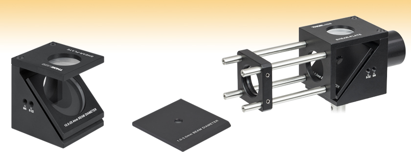
- Magnetic Steel Balls Secure the Shear Plate to the Base
- Applicable Beam Diameters Engraved on Shear Plate
These Shearing Interferometers can be used with incident beams as small as Ø1 mm and as large as Ø50 mm depending on which shear plate is used. The interference pattern is sensitive to the beam divergence and can be used to qualitatively determine whether the beam is collimated. The shear plate has three steel balls fixed to the bottom of the plate that attach magnetically to the base. This magnetic retention mechanism enables easy swapping of plates when different beam diameters are used. Please see the Specs tab for compatible plates and bases.
In addition, there is a hole drilled into the back plate of the base, enabling the light that is transmitted through the wedged optical flat to continue unimpeded. Please note, the output angle and position will be affected by the wedge angle and thickness of the shear plate used. For all models except the SI500 interferometer, this output hole has internal SM1 (1.035"-40) threads and has four 4-40 tapped holes around it for integration into our 30 mm Cage System. The SI500 output is a Ø2.95" (Ø75 mm) smooth bore. The base, diffuser plate, and shear plate come packaged in a carrying case.
Please note that due to the thickness of the shear plate optic in the SI100, SI254, and SI500 inteferometers, the back surface of the shear plate protrudes from the mounting plate as can be seen in the image to the right. Therefore, care should be taken when inserting or removing these plates from the base unit, especially if the SICP or SICPSM1 cage adapter plates are installed.

 Zoom
Zoom
- 5 Models Available for Beam Diameters Ranging from 1 mm to 50 mm
- Compatible with Multiple Shearing Interferometer Bodies
- Magnetic Steel Balls Secure the Plate to the Base
- Applicable Beam Diameters Engraved on Plate
Thorlabs offers five interchangeable shear plates, which together are designed to be used with incident beam diameters ranging from 1 mm to 50 mm. As seen in the image at the right, the shear plates each have three steel balls fixed to the bottom of the plates that attach magnetically to the base. The magnetically coupled kinematic design of these plates allows them to be precisely positioned on the shearing interferometer. Multiple plates are compatible with the same base (see the table below for compatibility), thus enabling the plate to be interchanged easily if the beam diameter being used for a particular experiment changes. Different shear plates are offered for different diameter beams due to the optimization of the wedge angle for the beam diameter.
Please note that due to the thickness of the shear plate optic in the SI100, SI254, and SI500 inteferometers, the back surface of the shear plate protrudes from the mounting plate as can be seen in the image to the right. Therefore, care should be taken when inserting or removing these plates from the base unit, especially if the SICP or SICPSM1 cage adapter plates are installed.
| Item # | Beam Diameter for Included Plate | Compatible Shearing Interferometer Base Item # |
|---|---|---|
| SI035P | 1 - 3 mm | SI035, SI050, SI100, and SI254 |
| SI050P | 2.5 - 5 mm | SI035, SI050, SI100, and SI254 |
| SI100P | 5 - 10 mm | SI035, SI050, SI100, and SI254 |
| SI254P | 10 - 25.4 mm | SI035, SI050, SI100, and SI254 |
| SI500P | 25.4 - 50 mm | SI500 |

 Zoom
Zoom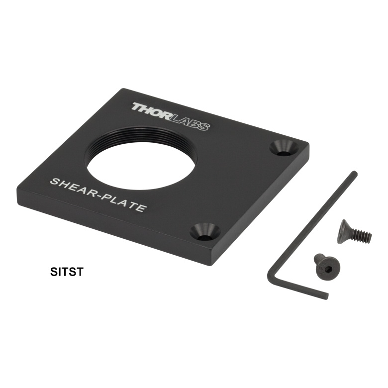 Click to Enlarge
The SITST Mounting Plate has internal SM1 threads and comes with two 4-40 cap screws and a 1/16" hex key.
- Recommended for Beam Diameters from 1 mm - 10 mm
- Increases the Size of Fringes on the Diffuser Plate
The SIVS Magnified Viewing Screen is helpful for viewing the fringe pattern created by a small diameter beam. By replacing the standard diffuser plate viewing screen on the SI035, SI050, SI100, or SI254a interferometers with this accessory, the size of the fringes will increase, thereby making it easier to determine if the light is collimated. Magnification of the fringe pattern is achieved by using a LC2265 N-SF11 Plano-Concave Lens at the base of the assembly.
If desired, the mounting plate for the SIVS viewing screen can be purchased separately (Item # SITST). It features a standard Thorlabs internal SM1 (1.035"-40) thread, which is compatible with any of our SM1-threaded components.
Both the SIVS viewing screen and the SITST mounting plate come with two 4-40 cap screws and one 1/16" hex key so they can be secured to the shearing interferometer.
| Item # | Description | Compatible Shearing Interferometer Base Item # |
|---|---|---|
| SIVS | Magnified Viewing Screen System | SI035, SI050, SI100, and SI254a |
| SITST | SM1-Threaded Mounting Plate | SI035, SI050, SI100, and SI254 |

 Zoom
Zoom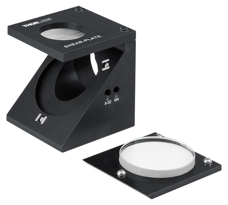
Click to Enlarge
The SICP Cage System Adapter replaces the diffuser plate included with the shearing interferometer and can be secured using the two included 4-40 screws.
- Integrate a Shearing Interferometer into a 30 mm Cage System
- Replaces the Standard Diffuser Plate Viewing Screen Provided with the Shearing Interferometers
- Two Versions Available:
- Integrated Diffuser Plate
- Integrated Viewing Plate with Internal SM1 (1.035"-40) Threads
These two adapter plates are designed to replace the standard diffuser plate viewing screen on a SI035, SI050, SI100, or SI254 interferometer and enable the input side of the shearing interferometer to be attached to a 30 mm cage or SM1 lens tube system. The SICP Adapter offers a diffuser for viewing the fringes, while the SICPSM1 Adapter has internal SM1 (1.035"-40) threads, allowing a Ø1" lens tube to be attached where the fringes would normally be viewed.
Since these plates feature tapped 4-40 holes for attaching the cage system, the plate cannot be attached to an existing cage system. The ERSCB cage rod adapters will allow this plate to be inserted and removed without having to disassemble the cage system.
| Item # | Description | Compatible Shearing Interferometer Base Item # |
|---|---|---|
| SICP | 30 mm Cage System Adapter with Viewing Screen | SI035, SI050, SI100, and SI254 |
| SICPSM1 | 30 mm Cage System Adapter with SM1-Threaded Viewing Port | SI035, SI050, SI100, and SI254 |