 Products Home / Imaging Systems / OCT Imaging Systems & Components / OCT Components / Interferometers / Michelson-Type Interferometer
Michelson-Type Interferometer
- Compact OCT Proven Michelson-Type Interferometer
- Low Insertion Loss
- Flat Wavelength Response
- Input for Alignment Laser
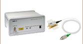
INT-MSI-1300B
Power Supply Included


Please Wait
| Item # | INT-MSI-1300 | INT-MSI-1300B |
|---|---|---|
| Optical | ||
| Interferometer Wavelength Range | 1250 - 1350 nm | |
| Fiber Type | SMF-28e+ | |
| Input/Output Port | FC/APC | |
| Insertion Lossa from 1300 nm IN to Sample Arm and to Reference Arm |
<4.2 dB (Typical) 5 dB (Max) |
|
| Insertion Lossa from 660 nm IN to Probe |
<3 dB (Typical) 4.5 dB (Max) |
|
| Path Length Difference | <0.1 mm (Typical) 0.2 mm (Max) |
|
| Electrical | ||
| Detector Material/Type | InGaAs/PIN | |
| Detector Wavelength Range | 800 - 1700 nm | |
| Typical Responsivity (Max) | 1.0 A/W | |
| Output Bandwidth (3 dB) | DC - 15 MHz | DC - 100 MHz |
| Transimpedance Gainb | 51 kV/A | 100 kV/A |
| Saturation Power | 70 µW | 35 µW |
| Maximum Input Power | 20 mW | |
| Electrical Output | SMA | |
| DC Offset | <±5 mV | |
| Power Supply | ±12 V @ 250 mA (100/120/230 VAC, 50 - 60 Hz, Switchable) (PICO M8 Connector) |
|
| General | ||
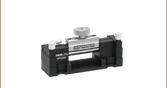
| Dimensions | 4.72" x 3.15" x 0.827" (120 mm x 80 mm x 21 mm) |
|
Features
- Minimal Variation in Polarization Dependent Coupling Ratio (PDCR)
- Integrated Balanced Signal Detection with Active Aliasing
- Input for Aiming Beam (660 nm) to Aid in Alignment
- Interferometer Power Supply Included
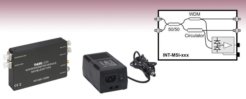
The Michelson-type INT-MSI-1300 and INT-MSI-1300B interferometer subassemblies are designed to be used inside an OCT system with a balanced detection scheme for a wavelength range of 1250 to 1350 nm. For usage with faster sweeping lasers the bandwidth of the integrated detectors of the INT-MSI-1300B has been increased up to 100 MHz. Each module contains a fiber coupler network for a Michelson interferometer with outputs for the reference arm and the sample arm. The INT-MSI-1300 and INT-MSI-1300B only differ in the above mentioned bandwidth, the transimpedance gain, and their saturation power, see the table to the right for more information.
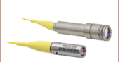
Internally used couplers are optimized for flat wavelength response and very low polarization dependent coupling losses. The fiber length is matched on both arms of the interferometer to within 0.2 mm while the housing includes FC/APC angled fiber adapters for robustness and ease of use. To suppress the generation of aliasing frequencies in the digitized fringe signals, which degrade the image quality, the integrated, high-gain balanced detector includes an active aliasing filter.
To support aligning the INT-MSI-1300 and INT-MSI-1300B into optical systems, an additional input for a 660 nm aiming laser and a specially designed WDM-coupler that combines the swept laser source (1300 nm) and the alignment laser (660 nm) were included in the subassembly.
Power Monitor Output
SMA Female
0 - 1.8 V (50 Ω) or 0 - 3.6 V (High Z)
Figure 1 shows a sample setup of the INT-MSI-1300B in a Time Domain OCT system. The incoming broadband light source, which has a central wavelength of 1300 nm, passes through a circulator and a broadband 50/50 fusion coupler. Back-reflected light from both the sample and reference arms of the interferometer are combined in the 50/50 fusion coupler, generating the interference fringe signals that pass through the circulator and the WDM coupler to the inputs of the balanced detector. The balanced detector output signal is acquired by the data acquisition device and processed to obtain the reconstructed OCT image. Figure 2 is a schematic showing how the IN-MSI-1300B can be incorporated into a frequency domain OCT system by replacing the translating mirror on the end of the reference arm with a fixed mirror.
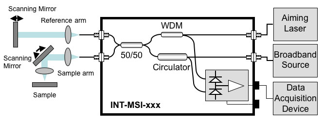
Figure 1: Schematic of the INT-MSI-1300B in a Time Domain OCT Design
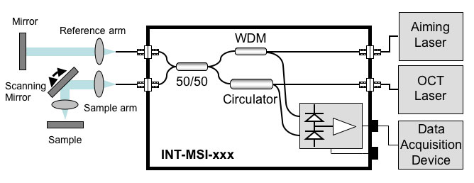
Figure 2: Schematic of the INT-MSI-1300B in a Sample Fourier Domain OCT Design
The internal fiber length of both arms of the interferometer match to within 0.2 mm, while the optical path lengths between the 50/50 fusion coupler and the inputs of the balanced detector are also matched to achieve optimal noise suppression (i.e., the maximum common mode rejection ratio CMRR). The internal couplers are optimized for flat wavelength response and very low PDCR (polarization-dependent coupling ratio), which makes the detected signal nearly independent of input polarization changes. Figure 3 shows the percentage of the input power at the reference and sample ports. Equal power for both ports is measured at 1300 nm (center wavelength).

Figure 3: Coupling of the INT-MSI-1300B Measured From 1300 nm IN Port to the SAMPLE and REFERENCE ARM Ports
| Posted Comments: | |
Ela Öztürk
(posted 2023-10-20 03:52:47.35) Hi, can I learn the information about this product's displacement resolution, velocity resolution, acceleration resolution and sensor resolution, if you have data? dpossin
(posted 2023-10-23 08:33:49.0) Dear Elanur,
Thank you for your feedback.
The INT-MSI-1300 is a fiber-based Michelson interferometer and has an analog output. If used in an OCT system, the resolution of the complete system, would be dependent on the setup and all components used. Nathan Eschbach
(posted 2022-04-13 13:38:56.127) I am confused by the diagram and description for the operating principle here. If the mixed single is mixed in a 50/50 after the sample is probed, and then each arm of that 50/50 goes to each input of the balanced detector, then the balanced detector is receiving the exact same signal at each input and there is no comparison to be made. Can someone please comment on this? fmortaheb
(posted 2022-04-25 05:26:02.0) Dear Nathan,
Thank you very much for your feedback. I will contact you directly to discuss the operating principles in more detail. marc miousset
(posted 2020-03-16 18:12:49.083) Hi,
I would like to test INT-MSI-1300B with laser diode
in Input OCT Laser, LPSC-1310-FC (not OCT).
Do you tkink it will be OK (the SLD DIODE are to expensive).
Thank You
Marc MKiess
(posted 2020-03-18 10:35:16.0) This is a response from Michael at Thorlabs. Thank you very much for the inquiry. In general, you can also use the input with other lasers. The laser you use, depends on your exact application. However, note that the laser you mentioned has FC/PC connectors, while the input of the INT-MSI-1300B has FC/APC connectors. I have contacted you directly to discuss your application, possible alternatives or special designs. Minsuk Lee
(posted 2020-02-11 21:07:26.027) Can you specify the electrical delay of the system?
I am trying to calculate the optimized k-trigger delay time of the swept-source laser for the OCT system.
Best regards,
Minsuk Lee MKiess
(posted 2020-03-02 05:12:21.0) This is a response from Michael at Thorlabs. Thank you very much for the inquiry. The electrical propagation time between detector and output socket (RF port) is negligible.
This time results only from a few centimeters of conductor paths with an amplifier.
Approximately one can say that the electrons are as fast as light. At 10 cm that makes about 0.5 ns.
In general, the difference in optical propagation time, depending on the experimental setup, is the more significant. Of course this depends strongly on the experimental setup.
The INT-MSI box causes a delay of about 9.2 ns, whereby this value does not take into account the propagation time between the INT-MSI box and the sample.
I have contacted you directly to discuss this in more detail. Erick Ulin Avila
(posted 2020-01-23 13:49:17.437) need to know the operating and storage temperaturas. Thanks in advance MKiess
(posted 2020-01-27 04:45:25.0) This is a response from Michael at Thorlabs. Thank you very much for the inquiry. The operating temperature range is 0°C to 40°C, whereas the storage temperature range is from -40°C to 70°C. syhamadani
(posted 2017-01-19 18:57:48.58) Can this product (or the Mac Zhender) be used in a FROG system (or other autocorrelation interferometric system) to measure the pulsewidth of picosecond fiber lasers (0.1 to 5 psec)? wskopalik
(posted 2017-01-20 03:56:28.0) This is a response from Wolfgang at Thorlabs. Thank you very much for the inquiry. I will contact you directly to discuss your requirements and to provide further assistance. bass_1526
(posted 2017-01-12 01:20:11.433) Hello, I have a cuestión about what kind of accessories I need to buy if I want to use the Michelson OCT interferometer for to preforme measured in domino time... specific for the measure micro-displacements... Specifically for the reference arm. Thanks swick
(posted 2017-01-12 06:18:27.0) This is a response from Sebastian at Thorlabs. Thank you for the inquiry.
A schematic setup for the Time-Domain design and the Fourier-Domain design can be found on tab "Operating Principles".
I will contact you directly for further assistance. marino.biom
(posted 2015-01-27 11:59:11.19) Hello,
Can I use this interferometer for a SD-OCT setup, in 1300 nm range? In thise case, how works the detection system? Need I to buy a spectrometer? Thanks in advance
Best regards shallwig
(posted 2015-01-28 06:27:39.0) This is a response from Stefan at Thorlabs. Thank you very much for your inquiry. This Michelson Type interferometer is not suitable for SD-OCT applications. From its working principle with the built in balanced detectors which are used for detecting interference fringes these interferometers are a subassembly to be used in both swept source Fourier domain and time domain OCT systems. For spectral Domain (SD) OCT you need a spectrometer to measure the interference signal as function of wavelength. I will contact you directly to discuss your application and your needs in detail. fixed-term.Ahmad.Sabbagh
(posted 2013-10-14 15:57:52.777) Hello,
we have a special made interferometer without the DC components.
First testings seems to be Okay, but we found out that we have much noise in the sample and reference arm. The sensitive fiber cable in these arms effects the output, there must be polarisations which makes these interferometer useless for our project. Can you explain this phenomena maybe. The polarisation comes after the circulator ? We are not sure from where. To find a way to solve it we need more informations on that.
Thank you!
Best regards.
Ahmad Sabbagh
Robert Bosch GmbH Stuttgart Feuerbach tschalk
(posted 2013-10-24 04:41:00.0) This is a response from Thomas at Thorlabs. Thank you very much for your inquiry. It is important that you measure the polarization in the sample and reference arm. The polarization effects inside the interferometer should not cause that much noise. I will contact you directly to discuss your application. tschalk
(posted 2012-12-13 09:28:00.0) This is a response from Thomas at Thorlabs. Thank you very much for your inquiry. Although we are not able to share information about the electronics in the equipment we will be happy to discuss your needs and work together to produce a modified version that would be suitable for your application. If that would be an interesting option for you we can discuss the modifications that would be required. I will contact you directly for more detailed information. avle
(posted 2012-12-13 03:05:10.203) hi there, could you share the electrical schematic for the balanced detector used in the unit? We'd like to make some modifications to it.
Thanks! bdada
(posted 2012-02-24 15:40:00.0) Response from Buki at Thorlabs to avle:
Thank you for your feedback. We will contact you with more information and post an update here soon. avle
(posted 2012-01-26 03:16:24.0) Hi there, what is the max sweep rate for the swept source laser that can be used with the 100mhz version of the unit?
How would one go about calculating the frequency bandwidth required for the detector based on sweep frequency of the swept source laser?
Thanks! bdada
(posted 2011-10-17 12:41:00.0) Response from Buki at Thorlabs:
Thank you for using our feedback tool. The power supply used is the LDS1212-1 and the description is Power Supply, ±12 VDC, 6W, 115/230 VAC. It is not available on our website but you can purchase it by calling or emailing our Sales Department at 973 300 3000 or sales@thorlabs.com. yubo.duan
(posted 2011-10-17 06:59:57.0) Dear Sir/Madam,
We bought INT-MSI-1300B before. Now its power supply is broken by accident. We want to buy a new one, but I didn't find how to order the power supply individually online. Also I didn't find the same one in the local electronic trade counters. Could you help me please? I'm in Singapore. Thanks a lot.
Best wishes.
- Duan Yubo jjurado
(posted 2011-08-15 12:15:00.0) Response from Javier at Thorlabs to avle: Thank you very much for contacting us. We offer a variety of table clamps and kinematic stops that you can use in order to secure the interferometer onto the bottom of your optical table. Take a look at the links below:
http://www.thorlabs.com/NewGroupPage9.cfm?ObjectGroup_ID=191
http://www.thorlabs.com/NewGroupPage9.cfm?ObjectGroup_ID=176
I will contact you directly for further support. avle
(posted 2011-08-15 01:56:00.0) hi there, what would be the cost to get a replacement cover for the interferometer that would allow it to be bolted to an optical breadboard.
Having this feature for future products would be highly useful.
Thanks! jjurado
(posted 2011-06-16 11:50:00.0) Response from Javier at Thorlabs to avle: Thank you very much for submitting your inquiry. We will contact you directly to assist you with your application. avle
(posted 2011-06-15 16:38:33.0) We have purchased this unit and are testing it with our swept source laser.
We are having some issues getting fringe outputs from the unit.
With the reference arm aligned, i see the a waveform output that corresponds to the power vs time output of the laser. Should I be seeing this, or some actual fringes?
Also, I am having a hard time using the F280APC-C fiber collimators to get aligned. Are these more sensitive/harder to align generally?
When I switch to a GRIN based collimator it seems easier to align.
Also regarding the use of a neutral density filter, what optical density would you recommend?
Some help on getting started would be great!
Thank you!
~Anthony klee
(posted 2009-10-08 18:02:51.0) A response from Lina at Thorlabs to mo_kamal: Thank you for your interest in Thorlabs products in particular our OCT system components.
In regards to your questions, you can use the Michelson interferometer with the Swept Source laser.
From your email it seems like you are planning to build an OCT system, for that we recommend the balanced detectors that then will be connected to the NI card. Below you can see the link for the detector:
http://www.thorlabs.com/NewGroupPage9.cfm?ObjectGroup_ID=2151
You might as well take a look at other OCT components that you might require for your set up:
http://www.thorlabs.com/navigation.cfm?Guide_ID=902
We also sell complete OCT system ready to use:
http://www.thorlabs.com/NewGroupPage9.cfm?ObjectGroup_ID=2098 mo_kamal
(posted 2009-10-08 15:40:47.0) Hi
Can we use it for OCT imaging with Thorlabs SLD1325 light source?
Do we need any camera?
Or we can just plugin NI data acquisition card for data acqusition?
if camera is required what kind of camera recommonded? can we buy them from Thorlabs?
Thanks
Kamal mo_kamal
(posted 2009-07-14 12:45:00.0) 1. INT-MSI-1300 - Michelson-Type Interferomete would be useful for 1000nm centre wavelength with a spectral bandwidth of 200nm for OCT application....
2. What kind of detector/ data acquisition card recommonded with this types of inteferometer for OCT Tyler
(posted 2009-04-29 14:41:47.0) A response from Tyler at Thorlabs to nmorel: The fiber coupler element found inside the Michelson-Type Interferometer would have a much narrower bandwidth (~20 nm) for an interferometer with a central wavelength of 830 nm. Is this acceptable for your application? Thank you for your inquiry. nmorel
(posted 2009-04-27 09:39:09.0) you have a INT-MSI-1300 - Michelson-Type Interferomete in 830 nm ??? |