Gimbal Mirror Mounts
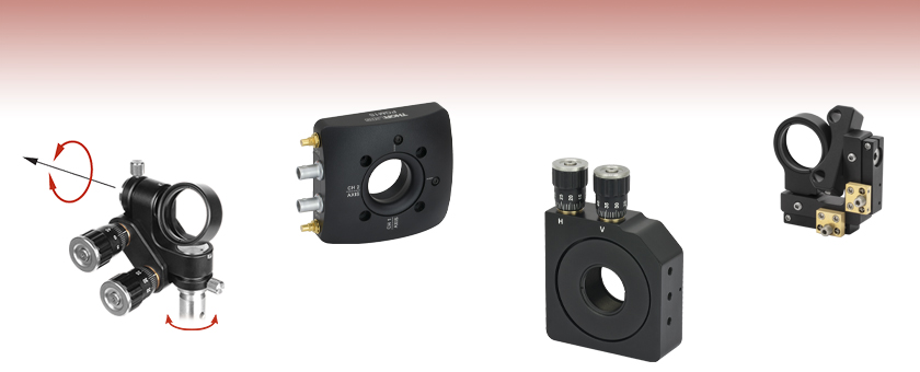
- Pure Rotational Motion About Center of Mirror Face
- Minimal Crosstalk Between Axes
- Compatible with Ø1/2" Posts or 30 mm Cage Systems
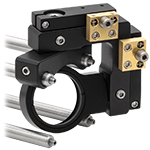
GMB1
Full Gimbal Mount for Ø1" Optics
(Post Not Included)
GM100
Gimbal Mount for Ø1" Optics
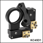
KC45D1
Gimbal Mount for Ø1" Optics
30 mm Cage Compatible
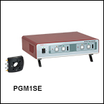
PGM1SE
Piezoelectric Gimbal Mount (Includes Controller)

Please Wait
Click to Enlarge
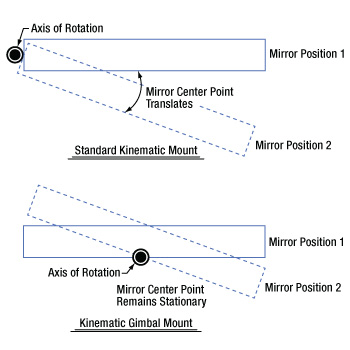
Comparison of Standard Kinematic Mount and Gimbal Mirror Mount
Features
- Manual Gimbal Mirror Mounts with Hardened Steel Inserts
- True Gimbal Rotation About Mirror Center without Translation
- Durable and Stable Design
- Fabricated from Black Anodized Aluminum
Thorlabs offers a series of gimbal mirror mounts that provide rotation without translation; in each case, rotation occurs about the center of the mounted optic's front surface. All of these gimbal mounts are designed to eliminate angular or positional crosstalk when steering a beam of light.
The GMB1(/M) gimbal mirror mount offers coarse 360° adjustment in both axes and fine ±15° adjustment, also in both axes. For those working in tight spaces, the GM100(/M) Ø1" gimbal mount and GM200(/M) Ø2" gimbal mount have two adjuster knobs located on the top of the mount for easy access. The final manual option, the KC45D1 gimbal mirror mount, can be integrated into a 30 mm cage system.
For applications requiring the use of motorized gimbal mirror mounts, the PGM1SE(/M) Ø1" gimbal mount has two axes of rotation. Each axis has a piezoelectric angular range of 30 mrad with a resolution of 0.05 µrad in open-loop mode. Built-in strain gauge feedback allows for closed-loop operation, which provides a 20 mrad angular range and 0.14 µrad resolution. The gimbal mount is shipped with a factory-calibrated controller that supports Kinesis® and APT™ motion control software.
These gimbal mirror mounts utilize hardened steel inserts to reinforce all key wear points.
| Posted Comments: | |
Dan Ray
(posted 2023-06-26 13:44:44.807) Hello, is it possible to know the smallest angular displacement attainable on the GM100, and how does it compare to a standard KM100 ? Thanks ! jdelia
(posted 2023-06-26 01:02:36.0) Thank you for contacting Thorlabs. We do not specify a smallest angular displacement for either mount as that is dependent on the dexterity of the end user. However, if you are interested in angular resolution, that would be around 0.37 degree/rev for the KM100. We do not have anything more specific than that since the KM100 knob does not have graduations. Regarding the GM100, there are 50 graduations per revolution, and we do not have a singular resolution specification since the motion is not perfectly linear. We do have angular displacement data available under the "Overview" section of the product family page, as well as at the following link: https://www.thorlabs.com/images/TabImages/Gimbal_Mount_Angular_Displacement.xlsx. Simonas Indrišiūnas
(posted 2022-03-23 03:58:40.717) Hello,
is it possible to use Thorlabs motorized actuators with 1/4"-80 mounting thread for the GM100 mirror mount? jdelia
(posted 2022-03-24 08:21:07.0) Thank you for contacting Thorlabs. Unfortunately, we do not offer any motorized actuators that are compatible with the GM100 mount, as the mount uses 3/16"-100 threaded adjuster screws. The only gimbal mount we offer with motorized capability is the PGM1SE. I have contacted you directly to further discuss your application. user
(posted 2021-12-21 13:35:01.64) The point of rotation is stated as being the center of the optic's surface. Surely this cannot be true for any optic thickess or position within the mount. There can only be one point in space within the mount for which the movement is purely rotational. Where is that point? jgreschler
(posted 2021-12-27 12:06:34.0) Thank you for reaching out to Thorlabs. The gimbal surface is defined by the inside lip of the mounting bore. This is also the surface that the mirror surface would rest on making the point of rotation the front center of the mirror surface. Daniel Repp
(posted 2021-08-02 07:17:36.35) Hello!
I was wondering if you also have a Gimbal mount for 2 inch optics and how expensive this would be.
Best Regards
Daniel YLohia
(posted 2021-08-05 01:22:50.0) Hello Daniel, thank you for contacting Thorlabs. Unfortunately, we don't have a 2" option for the GMB1. That being said, we do offer the GM200, which is a gimbal mount for 2" optics. user
(posted 2021-04-21 15:49:45.237) Dear Thorlabs,
Are you selling a motorized version of the GMB1/M Gimbal mount? And if you don't, do you know if the control knobs can be replace by a stepper motor? YLohia
(posted 2021-04-29 01:43:47.0) Hello, we are currently selling the PGM1SE/M Piezoelectric Gimbal Mirror Mount. Unfortunately, the GMB1/M cannot be motorized. Ludo
(posted 2021-03-16 07:49:22.33) Your GMB1/M is great but I actually rarely use the micrometers for fine adjustment, the manual coarse adjustments in pitch and yaw are well damped and with a bit of practice have suffice for most of my needs. So I am writing you to suggest that you offer a version of this gimbal without the fine adjusters, and of course at a lower cost than the GMB1/M. YLohia
(posted 2021-03-16 12:12:52.0) Hello, thank you for your feedback. We currently don't offer these, but we will consider adding such items to our catalog in the future. nentezarian
(posted 2018-09-18 09:32:14.907) Are the GM100 micrometer adjusters lockable? YLohia
(posted 2018-09-18 03:53:44.0) Hello, thank you for contacting Thorlabs. Unfortunately, the adjusters on the GM100 are not lockable. gesuele
(posted 2017-01-22 14:23:18.817) Is it possible to use gimbal mount replacing its manual actuators with two motorized ones? In order to use it as alternative to galvomirror?
If yes what motorized actuator do you suggest? user
(posted 2016-05-04 21:55:04.29) Although the GM100/M is presented as metric, the M4 tapped holes are 0.5in and 1in apart, and not 25mm!
Can you make the M4 tapped holes 25mm apart? Thanks besembeson
(posted 2016-05-05 11:37:14.0) Response from Bweh at Thorlabs USA: We will review this drawing. You can contact me at techsupport@thorlabs.com for updates. max1034
(posted 2016-04-08 04:21:51.93) when i control the pitch and yaw to get light alignment, if it doesn't working, what should i do? besembeson
(posted 2016-04-11 11:53:22.0) Response from Bweh at Thorlabs USA: I will contact you to further discuss your application. user
(posted 2013-07-25 15:47:36.893) You really need to make a GMB1S serie for square optics, built with extreme low tolerance on the horizontal alignment (fixed roll at 0°).
Everytime you sell a $70 grating, Newport sells a $300 gimball mount, just because your KGM serie is so not convincing: they lack the roll axis and can't even be placed on the rotation axes of the GMB1, or any KMxxx. cdaly
(posted 2013-07-25 18:45:00.0) Response from Chris at Thorlabs: Thank you for your feedback. I have begun an internal discussion with our engineers regarding your request. We are currently in the final stages of designing a gimbal prism mount and I believe we may be able, with some redesign, offer this as a grating solution as well. jeff.bull
(posted 2013-03-08 18:03:55.66) What is the angle per revolution for the GM100/M? The pdf cad drawing says 0.035deg/rev, while for the GM100 it says 0.35deg/rev. On my GM100/M I am seeing about 75% of the 0.35 value, so about 0.26deg/rev.
What is it supposed to be and how much variation can I expect to see from the spec across the adjustment range?
thanks! jlow
(posted 2013-03-14 14:41:00.0) Response from Jeremy at Thorlabs: It seems that we made a mistake on the drawing for this. Please note that the angular displacement per revolution of the knob is not linear. I will e-mail you the angular displacement data for a GM100 we have on hand. Thank you for letting us know about this. We will be updating the web drawings shortly. hha07
(posted 2013-02-18 08:16:20.493) How does the Gimbal mount compare to the Polaris mount with respect to long term stability and angular positioning performance? cdaly
(posted 2013-02-27 15:50:00.0) Response from Chris at Thorlabs: Unfortunately we do not have any data directly comparing the gimbal points to the Polaris line. My sense is that the Polaris mounts are more thermally stable as this is one of the main reasons behind the design. i will contact you directly to discuss this further. tcohen
(posted 2012-04-19 15:41:00.0) Response from Tim at Thorlabs: Thank you for your feedback. The point of rotation for both axes is located at the center of the mounted optic’s surface. This does not have translational movement, but pitch and yaw. I will contact you with more information. scottrowe
(posted 2012-04-18 23:14:43.0) Where is the gimbal axes located within this mount? Obviously the center of the aperture for x and y, but z is not obvious. jjurado
(posted 2011-07-14 13:17:00.0) Response from Javier at Thorlabs to avle: The purpose of the two setscrews located at the top and bottom of the GM100 is not for locking the rotation of the mount. They are used to secure the back plate of the mount in place while the front plate rotates through the two gimbal axes. avle
(posted 2011-07-13 17:47:01.0) are the two set screws seen in the GM100 used for locking position of the mount? |

- True Gimbal Design
- Maximum Optic Thickness: 0.25" (6.4 mm)
- Mounts Ø1" (25.4 mm) Optics
- Fine Adjustment Provides ±15° at 1°/rev
- Fully Lockable Design
- Superior Kinematic Performance Without Crosstalk
The GMB1 Gimbal Mirror Mount, which is designed to hold Ø1" (Ø25.4 mm) optics up to 0.25" (6.4 mm) thick, features true gimbal motion in order to eliminate crosstalk when steering a beam of light. The point of rotation for both axes is located at the center of the mounted optic’s surface. Utilizing locking thumbscrews and fine pitch adjusters, the GMB1 offers both coarse adjustment and fine tuning. The coarse adjustment allows 360° of manual positioning for both angular degrees of freedom. The fine adjustment allows for ±15° of control, with rotation of the control knob yielding 1° of angular displacement per revolution. The yaw can be adjusted in a similar fashion using the thumbscrew and setscrew closest to the post. After the desired pitch and yaw position is established, the entire mount can be easily locked into place by tightening both thumbscrews and both setscrews. The minimal profile of this mount is ideal for tight beam paths.

Click to Enlarge
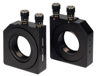
The photo above shows the front (left) and back (right) of the GM200 gimbal mirror mount.
- True Gimbal Design
- Maximum Optic Thickness: 0.63" (16 mm)
- GM100 - Mounts Ø1" (25.4 mm) Optics
- GM200 - Mounts Ø2" (50.8 mm) Optics
- Designed for Intra-Cavity Use
- Angular Range of ±2.5° (GM100) or ±2.0° (GM200)
- Graduated Adjuster Knobs, 100 TPI Adjusters
Thorlabs' Gimbal Mirror Mounts are designed for intra-cavity use, and incorporate a true gimbal design that locates the optical surface directly on the axis of rotation. The design provides pure rotational motion without angular or positional crosstalk.
Two adjustment knobs (graduated with 50 divisions per revolution) are located on the top surface of the mount, making them easily accessible even if the mount is integrated into an optical cavity. They provide excellent angular positioning performance. The GM100 is designed to hold Ø1" (Ø25.4 mm) optics, while the GM200 is meant for Ø2" (Ø50.8 mm) optics. The mounts are SM1- (1.035"-40) or SM2-threaded (2.035"-40), respectively, for compatibility with our lens tubes and accessories, and each mount includes a retaining ring for securing the optic.
Please Note: Due to the internal drive mechanism, the adjustment knobs on these mounts do not provide perfectly linear motion. For specific measurements, please click here.

Click to Enlarge
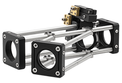
Gimbal mounts in combination with our swivel couplers are ideal for creating non-45° incident angles within a cage system.
Click to Enlarge
The KC45D1 Gimbal Mount in a 30 mm Cage System
- True Gimbal Design
- Maximum Optic Thickness: 0.24" (6 mm)
- Mounts Ø1" Optics
- Compatible with Thorlabs' 30 mm Cage System
- Full 360° Rotation of Optic Holder
- ±30° Rotation on the Optic Holder Saddle
The KC45D1 Gimbal Mirror Mount is designed to allow a Ø1" optic to be rotated about a point in the center of a 30 mm cage assembly with true gimbal motion. The optic holder is free to rotate through 360°. Once its coarse angular orientation is set, the fine adjustment mechanism (i.e., two 100 TPI adjusters offering an adjustment per revolution of 13 mrad/rev) can be used for precise alignment, using the HKTS-5/64 hex key thumbscrew or any other 5/64" hex key or balldriver. The second angular degree of freedom is achieved by rotation of an intermediate saddle. This saddle connects the optic holder to the cage assembly and is free to rotate ±30°. The optic is secured against the back lip of the SM1 (1.035"-40) center tapped region using the included SM1RR Retaining Ring.

| Key Specifications | ||
|---|---|---|
| Piezo Specifications | ||
| Resonant Frequency (7.0 g Load) | 360 Hz ± 15% | |
| Piezo Angular Range | 30 mrad (Open Loop) 20 mrad (Closed Loop) |
|
| Angular Resolution | 0.05 µrad (Open Loop) 0.14 µrad (Closed Loop)a |
|
| Piezo Control Voltage | -25 to 150 V | |
| Piezo Drive Connectors | Male SMCb | |
| Strain Gauge Connectors | Male 7-Pin LEMOb | |
| Mechanical Specifications | ||
| Optic Size | Ø1.00" (Ø25.4 mm) | |
| Optic Thickness | 2 mm (0.08") Min 7.5 mm (0.30") Max |
|
| Post Mounting Features | 8-32 (M4) Mounting Taps | |
| Cage System Compatibility | Four 4-40 Taps for 30 mm Cage Rods | |
- Strain Gauge Feedback Sensors for Closed-Loop Operation
- Designed for Use with Included Controller
- True Gimbal Rotation Maintains Stationary Center Point of a Mounted Optic
- High Angular Range: 30 mrad (Open Loop) or 20 mrad (Closed Loop)
- SM1-Threaded (1.035"-40) Optic Bore for Ø1" Optics
- Through Holes for Integration with a 30 mm Cage System
The PGM1SE(/M) Piezoelectric Gimbal Mirror Mount has two axes that each rotate the mounted optic about a gimbal axis, keeping the center of the optic in a fixed position. Each axis is capable of scanning over a high piezoelectric angular range of 30 mrad with a resolution of 0.05 µrad in open-loop mode (20 mrad angular range and 0.14 µrad resolution in closed-loop mode).
A Ø1" optic can be mounted in the SM1-threaded optic bore and secured with the included SM1 retaining ring. The mount can hold optics between 2 mm and 7.5 mm thick; the optic is installed via the back of the mount, which keeps the optic surface coincident with the gimbal axes, regardless of the optic thickness. We do not recommend mounting an SM1 lens tube to the threading as it will apply excessive torque to the gimbal element.
Six 8-32 (M4) tapped holes on the optic mount allow it to be mounted on a Ø1/2" post. Additionally, four 4-40 tapped holes around the optic bore on both sides of the mount provide compatibility with 30 mm cage systems.
The mount is shipped with a piezo controller that has been factory calibrated to the specific mount and supplies a voltage of -25 to +150 VDC. Piezo control is supported through the included Kinesis® and APT™ GUIs, either locally using the paired controller or by using an externally supplied control voltage. The controller offers USB and RS-232 interfaces for computer control, a BNC input for the addition of external drive signals, and a BNC output that gives either positioning feedback from the mount’s built-in capacitive sensors or a signal proportional to the piezo drive voltage. In addition, a DB15 connector provides signals that can be used for synchronization with external equipment. A USB 2.0 (A to B) cable is included.
For more information on the piezoelectric gimbal mount, please see the full web presentation.
 Products Home


 Zoom
Zoom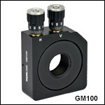
 Gimbal Mounts