Articulating Platforms
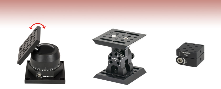
- Continuous Adjustment Over 90° or 180° Range
- Rapid Angular Positioning
- Locking Mechanism for Stability
Full 90°
Swing
SL20
Articulating Base Stage
AP180
Adjustable Angle Plate
FP90
Adjustable Flip Platform

Please Wait
Features
- Lockable Angular Positioning
- At Least 90° Total Adjustment Range
- Top Platforms Offer Array of Mounting Holes
These Articulating Platforms provide angular adjustment for components in an optomechanical setup.
Articulating Base
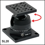
The SL20(/M) Articulating Base features 90° adjustment from a horizontal to a vertical platform position, as well as 360° rotation about the vertical axis. The mounting platform, which has an array of twenty-five 1/4"-20 (M6) tapped holes for mounting components, can be swung into nearly any arbitrary position.
Adjustable Angle Plate
The AP180(/M) Adjustable Angle Plate features 180° of angular adjustment. The top plate can be positioned at one of 13 discrete angles using the included linchpin, or it can be locked at any arbitrary position using the side-located locking screw with a 1/8" (3 mm) hex. The top plate features an array of 1/4"-20 (M6) tapped holes and 1/4" (M6) slots for mounting components on top.
Adjustable Flip Platform
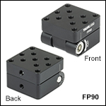
The FP90(/M) Adjustable Flip Platform is designed to be mounted on top of a Ø1/2" or Ø1" post using the #8 (M4) counterbore located in the center of the bottom plate, or the 8-32 (M4) tapped mounting hole on the side of either of the two plates. The angle of the top plate can be adjusted over a range of 90° or 180°, depending on the mounting orientation. The top surface of the flip platform features eleven 8-32 (M4) tapped holes for mounting components.
| Posted Comments: | |
Daniel Alastruey
(posted 2023-09-22 13:38:59.59) Hello.I am writing in reference to request information about how much load can handle the SL20/M. I have not found this
information in the specifications. Thank you very much in advanced. I look forward to hearing from you. Yours sincerely,
Dani. jdelia
(posted 2023-09-22 03:48:22.0) Thank you for contacting Thorlabs. The SL20 can support centralized loads of 50 kg or cantilever loads of 20 N·m (14 ft-lbs). mohammad moayad
(posted 2023-01-19 21:24:08.46) Hi
i am mohammad moayad project manager for construction works in qatar can you please reply to below inquiry.
do you have the same part which can resist 200 kg load.?
regards jdelia
(posted 2023-01-19 01:20:51.0) Thank you for contacting Thorlabs. We unfortunately do not offer an articulating mount that can handle a 200 kg load. I have reached out to you directly to discuss your application. Catherine Lanthier
(posted 2022-08-17 16:33:55.093) Hello,
We recently bought a Thorlabs Articulating base (SL20), and are experiencing some issues with the locking mechanism. When trying to lock the orientation of the base using the locking screw (3/16" hex socket locking screw), the ball remains loose within the socket, even when tightening the locking screw to its maximum possible. Is this a known issue with the Thorlabs SL20 part, and if yes, is there a way we can fix it on our side?
Thank you for your help,
Catherine jgreschler
(posted 2022-08-23 02:59:06.0) Thank you for reaching out to Thorlabs. I've contacted you directly to discuss setting up an RMA to repair the item. Iraj Ghazanfari
(posted 2022-01-12 20:29:55.53) Hello, I have an IR Camera 38 LB by 12"x8", Z=6", need to put on the top of the adjustable flip platform.
Can you recommend one for me, please? cdolbashian
(posted 2022-01-14 01:44:37.0) Thank you for contacting us at Thorlabs. We have few adjustable tilting platforms which can hold such a large load. I have contacted you directly to discuss the options which we have available. Vasili S
(posted 2021-09-22 03:57:22.103) Articulating Base SL20M: can I swing the platform in any direction e.g. towards me, to the right, left etc without rotating the entire assembly using the rotation stage? azandani
(posted 2021-09-23 11:01:21.0) Hello Vasili, thank you for contacting Thorlabs. Yes, that is correct. Engaging the locking screw locks both the ball and socket as well as the rotation mechanism at once. Despite this, the ball and socket can be easily adjusted in any direction without affecting the rotation when the locking screw is unlocked. Paul M
(posted 2019-05-14 10:43:12.14) What is the material? Thanks YLohia
(posted 2019-05-14 02:03:41.0) Hello, these articulating platforms are made of anodized aluminum. pmillho
(posted 2018-09-28 15:23:57.35) What are the dimensions for the hole pattern on the "universal base plate"? The hole pattern on the top is described but not for the base. Thanks YLohia
(posted 2018-10-02 09:10:46.0) Hello, thank you for contacting Thorlabs. Information on the hole patterns for nearly all of our opto-mechanical products can be found in their corresponding drawings, which can be accessed by clicking the red document icon next to the part number. The universal base plate contains four 1/4-20 (M6) counterbored holes on a 3" square. grb2116
(posted 2017-09-18 23:12:50.9) recently ordered this AP180 mount. Terrible terrible stability. The top plate was badly attached to the swinging arm. No way to re-tighten it. The screw threads were rusted. Too much of drift on the swinging fulcrum. The product needs serious thought on innovation for improved performance and acceptable stability. Would be a very useful product to the community if made well. tfrisch
(posted 2017-09-19 09:19:47.0) Thank you for contacting Thorlabs. We will certainly accept the AP180 platform back, and I will put you into contact with our RMA team to assist with that.
During the assembly process for AP180 the top and bottom plates are attached loosely and then after alignment tightened fully, but it sounds like this final tightening step didn't occur. Furthermore, we do use Loctite on those screws, so even if they weren't fully tightened the screws will be bound up by the Loctite.
As for the fulcrum, units that we have tested had an angular deviation of no more than ±0.3°, and if that is suitable for your application, we would also be able to provide you a replacement unit. I will reach out to you directly to discuss this. dstowell
(posted 2017-02-15 08:56:03.61) Question; is the SL20 a metal construction? jlow
(posted 2017-02-16 11:42:40.0) Response from Jeremy at Thorlabs: Yes, the SL20 is made from metal. emma.woolliams
(posted 2014-08-21 13:05:00.767) We're confused by this. The ball joint is useful, but we can't see how to use the rotational axis. The scale suggests that it should be possible to rotate it while keeping the ball joint locked in place in the cup (i.e. move the cup) - but there is no clear mechanism. We assumed the tiny little screws would do that - took ages to find an allen key that could actually undo them ... and nothing. So we can only rotate it by loosening the lock - and that means the ball can rotate relative to the cup and the scale is meaningless. Oh. Pity. Probably should have bought a straightforward rotation stage and the AP180... cdaly
(posted 2014-08-21 04:20:42.0) Response from Chris at Thorlabs: All rotation axis of the platform are achieved by pivoting the ball joint which the stage rest upon. It cannot be rotated in any direction without first unlocking the stage. It should be noted to that the dial and thus the position at which the platform can be made vertical can only be rotated before the platform is locked as well. If any rotation is required after the position is locked, an additional rotation stage would be required. |

Click to Enlarge
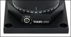
The engraved scale shows 2° angular position increments around the full 360° range.
- Rapid, Lockable Angular Positioning
- Full 90º Swing of Top Platform from Horizontal to Vertical Orientation
- Top Platform Offers 25 1/4"-20 (M6 x 1.0) Mounting Holes
- Full 360º Rotation of Entire Swivel Mechanism
- Universal Base Plate
The SL20 Articulating Base is a high-precision ball and socket mounting platform that provides free spherical motion over a complete hemisphere. Positional stability is provided via a heavy-duty 3/16" hex socket locking screw (see photo to the right) that can support centralized loads of 50 kg or cantilever loads of 20 N·m (14 ft-lbs). Applications include flexible inspection systems (video or optical microscope), target positioning, and detection systems.
The mounting platform features an array of twenty-five 1/4"-20 (M6 x 1.0) tapped holes on 0.5" (12.5 mm) centers. It can be tilted into arbitrary positions up to 90° with respect to the table surface. The entire ball and socket mechanism can be rotated 360° about the vertical axis. A laser-engraved scale offers 2° graduations, labeled every 10°. The counterbored slots in the base plate provide both imperial and metric compatibility.

- 180° of Discrete or Continuous Movement
- Lockable at 13 Locations, at 15° Increments, Using Included Linchpin
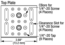
- Arrangement of Mounting Options as Seen in the Drawing to the Right
Thorlabs' Adjustable Angle Plate provides a full 180° of movement at 15° increments with ±18 arcmin precision. The mounting platform can be positioned at 13 discrete positions using the included linchpin. Engravings on the mount denote the angular positions possible and the associated pin location for each position.
In addition to the 13 discrete positions available, the plate can be oriented at any angle by tightening the hex locking screw. The mount has a maximum load of 35 lbs (15.8 kg) at the 60° inclination setting when using the linchpin. The load capacity is limited to 8 lbs if the linchpin is not used. This adjustable angle plate contains an array of 1/4"-20 (M6) mounting holes and 1/4" (M6) slots on the top and bottom plates as shown in the drawings to the right.
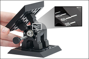
To change the angle between the two plates, loosen the 1/8" (3 mm) hex locking screw located on the back of the mount (see animation below). Once the hex screw is loose, remove the locking pin. Rotate the top plate until the engraved white line on the top plate hinge matches up with the desired angular marking on the bottom plate hinge. Insert the pin into the slot indicated by the letter in parentheses next to the angular position you selected. For example, to secure the top plate at 45° past vertical as shown in the photo below, the pin must be inserted into the A slot. Once the pin has been inserted, tighten the hex locking screw to fully secure the position of the mount.
Click to Enlarge
An engraved scale indicates 15° increments as well as the appropriate linchpin slot to use for each angle.
This animation shows how the AP180 Adjustable Plate can be locked at different angles.

Click to Enlarge
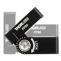
The adjustable flip platform can be set to a user-defined angle for components with specific mounting requirements. The engraved scale with 15° increments guides platform angle positioning.
- Designed for 90° Angular Adjustment
- Up to 180° Adjustment Range in Certain Configurations
- Side-Located Locking Cap Screw with 3/16" (5 mm) Hex
- 1.25" x 1.25" Mounting Platform with Eleven 8-32 (M4) Tapped Holes
- 8-32 (M4) Mounting Tap on the Side of Each Plate
- Four 8-32 Tapped Holes on the Bottom Plate for Additional Mounting Options
- Engraved Tick Marks in 15° Increments
The Adjustable Flip Platform is designed to attach to the top of our Ø1/2" or Ø1" posts and provide flexible mounting options for components. The flip platform can be secured on the post using the #8 (M4) counterbore located in the center of the bottom plate, or the 8-32 (M4) tapped mounting hole on the side of each of the two plates. The 1.25" x 1.25" top plate features eleven 8-32 (M4) tapped holes for mounting components.
The angle of the top plate can be adjusted between 0° and 90° with respect to the optical table surface when mounted using the counterbore in the center of the bottom plate. When mounted using the 8-32 tapped hole on the side, the top plate can be adjusted between -90° and +90° with respect to the optical table surface. In order to lock the platform in place, tighten the cap screw on the side using a 3/16" (5 mm) balldriver or hex key.
The flip platform can be converted between a right- and left-handed setup. Simply remove the locking screw, separate the top and bottom plates, flip the bottom plate upside-down, and reassemble the flip platform. This allows the user to choose the direction from which the locking screw is accessed, in case one orientation better suits the experimental setup.
Click here for test data on the effectiveness of the flexure locking screw.
Thorlabs offers additional products that can be used to place a mirror or other optical component at a fixed angle such as the post mounting angle blocks.
 Products Home


 Zoom
Zoom
 Articulated Bases