 Products Home
Fast Steering Mirror
- Two-Axis Steering on a Single Pivot Point
- Fast and Accurate X and Y Rotation
- Position Set by User-Supplied Voltage Signal
- ≥97% Average Reflectance from 450 nm to 2 µm
FSM75-P01
Cables, Power Supply,
and Controller Included


Please Wait
Included Components
- Fast Steering Mirror (Transportation Lock Included)
- Controller Box
- Power Supply with Fixed 4-Pin XLR Connector Cable
- Head Drive Cable, 16-Pin to Two 8-Pin Micro-Fit+ Connectors, 1.5 m
- Head Control Cable, 25-Pin SDR Connector, 1.5 m
Features
- Simultaneous Two-Axis Frictionless Steering on a Single Pivot Point
- Clear Aperture of Ø75.0 mm
- High Average Reflectance of ≥97% Over the 450 nm to 2 µm Wavelength Range
- Efficient Voice Coil Drive by Segmented Actuators (Patent Pending)
- Scanning Speed of 3 ms per Step (Up to a ±1.2° Mechanical Angle)
- Angular Range of ±6°
- Built-In Protection Against Overheating
- Digital Position Control Driven by User-Supplied Analog Voltage Signals
- Independent X and Y Axis Control
- Two BNC Connectors or 25-Pin Digital I/O Port Accept ±10 V Inputs
- Position Scales Linearly with Voltage
Applications
- High-Resolution Surface Scans with Defined Angle in Two Axes
- Rapid Prototyping
- Plastic Welding
- Steel Cutting and Welding with Beam Deflection
- Fast Optical Near Field Communication
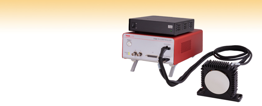
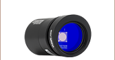
Thorlabs' FSM75-P01 Fast Steering Mirror is a fully motorized single-point mirror that provides high-speed beam deflection in two axes simultaneously. The mirror has a clear aperture of Ø75.0 mm, is supported by a flexure suspension system, and driven by specially-designed voice coils, allowing for large tilt ranges and fast acceleration. The included digital controller has an analog user interface to control mirror deflection and provides high linearity and millisecond settling with sub-microradian resolution and stability. The protected silver coating has a high average reflectance of ≥97% over the 450 nm to 2 µm range. This mirror is ideal for applications with high power lasers that require a step response time of down to 3 ms. See the Specs and Graphs tabs for more details on mirror performance.
The fast steering mirror consists of a mirror head, a controller box, and a power supply. The scanning movement of the optical mirror is controlled by a user-supplied input voltage, such as the output from a frequency generator. Both X and Y axes are completely independent and can follow different waveforms. For example, to drill a hole, a laser beam might be deflected using a sine signal in the X axis and a cosine signal in the Y axis to draw a circle. The controller box not only converts the analog voltage input into a digital drive signal to control the mirror's motion, but also monitors all parameters aside from the main steering function, such as the temperature of the mirror head and the position of the mirror with a local position sensitive detector (PSD). If the mirror head temperature is too high, the status LEDs will warn the user, and the system will reduce its performance or automatically shut off to protect itself. Please see the box above for a full list of the included components and the Front & Back Panels tab for more details.
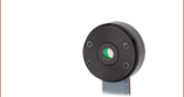
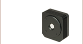
Mounting
Please mount the mirror head on an optical table or stable object which can also serve as a heat sink. The slots at the sides of the base of the mirror head accept M6 (1/4") screws (not included).
Click to Enlarge
The dimensions for the FSM75-P01 Fast Steering Mirror are given above. For more information on the LED status indicators and electrical connections, please see the Front & Back Panels tab above.
| Specificationsa | |
|---|---|
| Number of Axes | 2 (Tip Tilt) |
| Angular Range | ±6° (Mechanical) |
| Repeatability (For <2°) | <0.5 µrad (1σ) (Mechanical) |
| Stability (For <2°) | <0.5 µrad (1σ) (Mechanical) |
| Repeatability (For <6°) | <1.8 µrad (1σ) (Mechanical) |
| Stability (For <6°) | <1.8 µrad (1σ) (Mechanical) |
| Step Response (Up to ±1.2° Mechanical) | 3 ms (99%) |
| Linearity, ±4°, Mechanical | 99.8% |
| Linearity, ±6°, Mechanical | 99.5% |
| Resolution of Local Position Sensitive Detector (PSD) |
0.1 µrad |
| Thermal Drift | ≤20 µrad/K |
| Mirror Active Area | Ø75.0 mm |
| Mirror Pivot Point | 11.6 mm Behind Mirror Surface |
| Coating (Click for Reflectance Graphs) | Protected Silverb |
| Average Reflectance | ≥97% (450 nm to 2 µm) |
| Surface Flatness (RMS) | ≤λ/4 (633 nm) |
| Command Input | ±10 V (Rin = 15 kΩ; Differential) |
| Position, Position Difference Outputs | ±10 V (1 mA Max) |
| Thermal Protection | 60 °C (Mirror Head Temperature) |
| Digital Signal Input | Low: 0.0 V to 1.0 V High: 2.3 V to 3.3 V 10 kΩ Pull Up to 3.3 V |
| Digital Signal Output | Low: 0.0 V to 0.4 V High: 2.9 V to 3.3 V Iout ≤ 8 mA |
| Interconnect Cable Length | 1.5 m |
| Dimensions and Weight | |
| Mirror Head Dimensions (W x H x D) | 110.0 mm x 140.0 mm x 51.2 mm (4.33" x 5.51" x 2.01") |
| Controller Dimensions (W x H x D) | 199.8 mm x 104.9 mm x 323.8 mm (7.87" x 4.13" x 12.75") |
| Mirror Head Weight | 910 g |
| Controller Weight | 3.46 kg |
| Operating Conditions | |
| Operating Temperaturec | 0 to 40 °C |
| Storage Temperaturec | -40 to 70 °C |
| Absolute Maximum Ratings | |
| Damage Threshold CW | 4 W/cm (450 nm to 2 µm) |
| Damage Threshold Pulsed | 1 J/cm2 (1064 nm, 10 ns, 10 Hz, Ø10 mm) |
Fast Steering Mirror Performance
Click to Enlarge
The graph above shows the step response time as a function of the change in mechanical angle.

Click to Enlarge
The measurements above were taken for a mirror driven with a sinusoidal input voltage signal. The black and blue curves show the performance limits when the mirror is driven continuously. For the dark red, green, and red curves, the mirror alternates between oscillating at a set frequency and remaining in a static position with a 1:10 duty cycle. For example, the red curve represents operating conditions where the mirror oscillates for 200 ms out of every 2 second period. The regions above and to the right of each curve represent combinations of frequency and tilt angle for which the mirror will overheat under the indicated operating conditions. The periods of rest during interval operation provide time for the mirror to cool, allowing it to be operated at higher frequencies without over heating compared to when continuously driven.
Protected Silver Coating

Click to Enlarge
Click Here for Raw Data
The shaded region in the graph denotes the range over which we guarantee the specified reflectance. Please note that the reflectance outside of this band is typical and can vary from lot to lot, especially in out-of-band regions where the reflectance is fluctuating or sloped.
Mirror Back

| Callout | Description |
|---|---|
| 1 | Connector for Head Control Cable |
| 2 | Connector for White Head Drive Cable |
| 3 | M6 (1/4") Mounting Slots |
| 4 | Connector for Black Head Drive Cable |
| 5 | Cooling Lamellas |
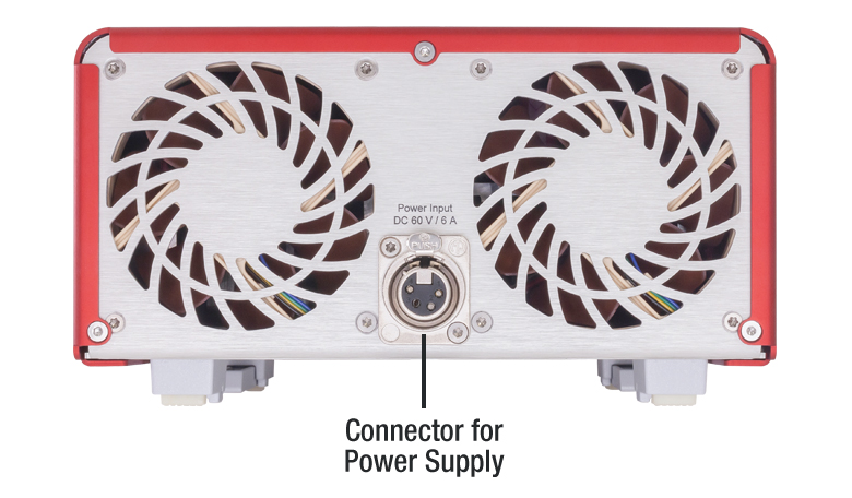
Controller Front Panel
Controller Back Panel

| Callout | Description | Callout | Description |
|---|---|---|---|
| 1 | Enable Button General Status LED |
5 | Y Target Signal Input (BNC Female, ±10 V) |
| 2 | Temperature Status LED | 6 | Analog/Digital I/O Connector |
| 3 | Current Status LED | 7 | Connector for Head Control Cable |
| 4 | X Target Signal Input (BNC Female, ±10 V) |
8 | Connector for Head Drive Cable |
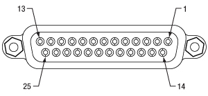
Pin Diagram
| Pin | Description | Pin | Description |
|---|---|---|---|
| 1 | Analog Input: Target Mirror Position X+ Differential Input, ±10 V |
14 | Analog Input: Target Mirror Position X- Differential Input, ±10 V |
| 2 | Ground | 15 | Ground |
| 3 | Analog Input: Target Mirror Position Y+ Differential Input, ±10 V |
16 | Analog Input: Target Mirror Position Y- Differential Input, ±10 V |
| 4 | Ground | 17 | Ground |
| 5 | Analog Output: Actual Mirror Position X (±10 V) | 18 | Analog Output: Actual Mirror Position Y (±10 V) |
| 6 | Analog Output: Position Difference X (±10 V) | 19 | Analog Output: Position Difference Y (±10 V) |
| 7 | Ground | 20 | Ground |
| 8 | Reserve (Do Not Connect) | 21 | Reserve (Do Not Connect) |
| 9 | Digital Input: Control Enable, Low Active | 22 | Reserve (Do Not Connect) |
| 10 | Reserve (Do Not Connect) | 23 | Ground |
| 11 | Digital Output: Controller Active, High Active | 24 | Digital Output: Current Warning, High Active |
| 12 | Digital Output: Current Error, High Active | 25 | Digital Output: Temperature Warning, High Active |
| 13 | Digital Output: Temperature Error, High Active | - | - |
Analog/Digital I/O Connector on Controller
Female 25-Pin D-SUB
| Damage Threshold Specificationsa | ||
|---|---|---|
| Item # | Type | Damage Threshold |
| FSM75-P01 | CW | 4 W/cm (450 nm - 2 µm) |
| Pulsed | 1 J/cm2 (1064 nm, 10 ns, 10 Hz, Ø10 mm) | |
Damage Threshold Data for Thorlabs' Fast Steering Mirror
The specifications to the right are measured data for Thorlabs' Fast Steering Mirror.
Laser Induced Damage Threshold Tutorial
The following is a general overview of how laser induced damage thresholds are measured and how the values may be utilized in determining the appropriateness of an optic for a given application. When choosing optics, it is important to understand the Laser Induced Damage Threshold (LIDT) of the optics being used. The LIDT for an optic greatly depends on the type of laser you are using. Continuous wave (CW) lasers typically cause damage from thermal effects (absorption either in the coating or in the substrate). Pulsed lasers, on the other hand, often strip electrons from the lattice structure of an optic before causing thermal damage. Note that the guideline presented here assumes room temperature operation and optics in new condition (i.e., within scratch-dig spec, surface free of contamination, etc.). Because dust or other particles on the surface of an optic can cause damage at lower thresholds, we recommend keeping surfaces clean and free of debris. For more information on cleaning optics, please see our Optics Cleaning tutorial.
Testing Method
Thorlabs' LIDT testing is done in compliance with ISO/DIS 11254 and ISO 21254 specifications.
First, a low-power/energy beam is directed to the optic under test. The optic is exposed in 10 locations to this laser beam for 30 seconds (CW) or for a number of pulses (pulse repetition frequency specified). After exposure, the optic is examined by a microscope (~100X magnification) for any visible damage. The number of locations that are damaged at a particular power/energy level is recorded. Next, the power/energy is either increased or decreased and the optic is exposed at 10 new locations. This process is repeated until damage is observed. The damage threshold is then assigned to be the highest power/energy that the optic can withstand without causing damage. A histogram such as that below represents the testing of one BB1-E02 mirror.

The photograph above is a protected aluminum-coated mirror after LIDT testing. In this particular test, it handled 0.43 J/cm2 (1064 nm, 10 ns pulse, 10 Hz, Ø1.000 mm) before damage.

| Example Test Data | |||
|---|---|---|---|
| Fluence | # of Tested Locations | Locations with Damage | Locations Without Damage |
| 1.50 J/cm2 | 10 | 0 | 10 |
| 1.75 J/cm2 | 10 | 0 | 10 |
| 2.00 J/cm2 | 10 | 0 | 10 |
| 2.25 J/cm2 | 10 | 1 | 9 |
| 3.00 J/cm2 | 10 | 1 | 9 |
| 5.00 J/cm2 | 10 | 9 | 1 |
According to the test, the damage threshold of the mirror was 2.00 J/cm2 (532 nm, 10 ns pulse, 10 Hz, Ø0.803 mm). Please keep in mind that these tests are performed on clean optics, as dirt and contamination can significantly lower the damage threshold of a component. While the test results are only representative of one coating run, Thorlabs specifies damage threshold values that account for coating variances.
Continuous Wave and Long-Pulse Lasers
When an optic is damaged by a continuous wave (CW) laser, it is usually due to the melting of the surface as a result of absorbing the laser's energy or damage to the optical coating (antireflection) [1]. Pulsed lasers with pulse lengths longer than 1 µs can be treated as CW lasers for LIDT discussions.
When pulse lengths are between 1 ns and 1 µs, laser-induced damage can occur either because of absorption or a dielectric breakdown (therefore, a user must check both CW and pulsed LIDT). Absorption is either due to an intrinsic property of the optic or due to surface irregularities; thus LIDT values are only valid for optics meeting or exceeding the surface quality specifications given by a manufacturer. While many optics can handle high power CW lasers, cemented (e.g., achromatic doublets) or highly absorptive (e.g., ND filters) optics tend to have lower CW damage thresholds. These lower thresholds are due to absorption or scattering in the cement or metal coating.

LIDT in linear power density vs. pulse length and spot size. For long pulses to CW, linear power density becomes a constant with spot size. This graph was obtained from [1].

Pulsed lasers with high pulse repetition frequencies (PRF) may behave similarly to CW beams. Unfortunately, this is highly dependent on factors such as absorption and thermal diffusivity, so there is no reliable method for determining when a high PRF laser will damage an optic due to thermal effects. For beams with a high PRF both the average and peak powers must be compared to the equivalent CW power. Additionally, for highly transparent materials, there is little to no drop in the LIDT with increasing PRF.
In order to use the specified CW damage threshold of an optic, it is necessary to know the following:
- Wavelength of your laser
- Beam diameter of your beam (1/e2)
- Approximate intensity profile of your beam (e.g., Gaussian)
- Linear power density of your beam (total power divided by 1/e2 beam diameter)
Thorlabs expresses LIDT for CW lasers as a linear power density measured in W/cm. In this regime, the LIDT given as a linear power density can be applied to any beam diameter; one does not need to compute an adjusted LIDT to adjust for changes in spot size, as demonstrated by the graph to the right. Average linear power density can be calculated using the equation below.

The calculation above assumes a uniform beam intensity profile. You must now consider hotspots in the beam or other non-uniform intensity profiles and roughly calculate a maximum power density. For reference, a Gaussian beam typically has a maximum power density that is twice that of the uniform beam (see lower right).
Now compare the maximum power density to that which is specified as the LIDT for the optic. If the optic was tested at a wavelength other than your operating wavelength, the damage threshold must be scaled appropriately. A good rule of thumb is that the damage threshold has a linear relationship with wavelength such that as you move to shorter wavelengths, the damage threshold decreases (i.e., a LIDT of 10 W/cm at 1310 nm scales to 5 W/cm at 655 nm):

While this rule of thumb provides a general trend, it is not a quantitative analysis of LIDT vs wavelength. In CW applications, for instance, damage scales more strongly with absorption in the coating and substrate, which does not necessarily scale well with wavelength. While the above procedure provides a good rule of thumb for LIDT values, please contact Tech Support if your wavelength is different from the specified LIDT wavelength. If your power density is less than the adjusted LIDT of the optic, then the optic should work for your application.
Please note that we have a buffer built in between the specified damage thresholds online and the tests which we have done, which accommodates variation between batches. Upon request, we can provide individual test information and a testing certificate. The damage analysis will be carried out on a similar optic (customer's optic will not be damaged). Testing may result in additional costs or lead times. Contact Tech Support for more information.
Pulsed Lasers
As previously stated, pulsed lasers typically induce a different type of damage to the optic than CW lasers. Pulsed lasers often do not heat the optic enough to damage it; instead, pulsed lasers produce strong electric fields capable of inducing dielectric breakdown in the material. Unfortunately, it can be very difficult to compare the LIDT specification of an optic to your laser. There are multiple regimes in which a pulsed laser can damage an optic and this is based on the laser's pulse length. The highlighted columns in the table below outline the relevant pulse lengths for our specified LIDT values.
Pulses shorter than 10-9 s cannot be compared to our specified LIDT values with much reliability. In this ultra-short-pulse regime various mechanics, such as multiphoton-avalanche ionization, take over as the predominate damage mechanism [2]. In contrast, pulses between 10-7 s and 10-4 s may cause damage to an optic either because of dielectric breakdown or thermal effects. This means that both CW and pulsed damage thresholds must be compared to the laser beam to determine whether the optic is suitable for your application.
| Pulse Duration | t < 10-9 s | 10-9 < t < 10-7 s | 10-7 < t < 10-4 s | t > 10-4 s |
|---|---|---|---|---|
| Damage Mechanism | Avalanche Ionization | Dielectric Breakdown | Dielectric Breakdown or Thermal | Thermal |
| Relevant Damage Specification | No Comparison (See Above) | Pulsed | Pulsed and CW | CW |
When comparing an LIDT specified for a pulsed laser to your laser, it is essential to know the following:

LIDT in energy density vs. pulse length and spot size. For short pulses, energy density becomes a constant with spot size. This graph was obtained from [1].
- Wavelength of your laser
- Energy density of your beam (total energy divided by 1/e2 area)
- Pulse length of your laser
- Pulse repetition frequency (prf) of your laser
- Beam diameter of your laser (1/e2 )
- Approximate intensity profile of your beam (e.g., Gaussian)
The energy density of your beam should be calculated in terms of J/cm2. The graph to the right shows why expressing the LIDT as an energy density provides the best metric for short pulse sources. In this regime, the LIDT given as an energy density can be applied to any beam diameter; one does not need to compute an adjusted LIDT to adjust for changes in spot size. This calculation assumes a uniform beam intensity profile. You must now adjust this energy density to account for hotspots or other nonuniform intensity profiles and roughly calculate a maximum energy density. For reference a Gaussian beam typically has a maximum energy density that is twice that of the 1/e2 beam.
Now compare the maximum energy density to that which is specified as the LIDT for the optic. If the optic was tested at a wavelength other than your operating wavelength, the damage threshold must be scaled appropriately [3]. A good rule of thumb is that the damage threshold has an inverse square root relationship with wavelength such that as you move to shorter wavelengths, the damage threshold decreases (i.e., a LIDT of 1 J/cm2 at 1064 nm scales to 0.7 J/cm2 at 532 nm):

You now have a wavelength-adjusted energy density, which you will use in the following step.
Beam diameter is also important to know when comparing damage thresholds. While the LIDT, when expressed in units of J/cm², scales independently of spot size; large beam sizes are more likely to illuminate a larger number of defects which can lead to greater variances in the LIDT [4]. For data presented here, a <1 mm beam size was used to measure the LIDT. For beams sizes greater than 5 mm, the LIDT (J/cm2) will not scale independently of beam diameter due to the larger size beam exposing more defects.
The pulse length must now be compensated for. The longer the pulse duration, the more energy the optic can handle. For pulse widths between 1 - 100 ns, an approximation is as follows:

Use this formula to calculate the Adjusted LIDT for an optic based on your pulse length. If your maximum energy density is less than this adjusted LIDT maximum energy density, then the optic should be suitable for your application. Keep in mind that this calculation is only used for pulses between 10-9 s and 10-7 s. For pulses between 10-7 s and 10-4 s, the CW LIDT must also be checked before deeming the optic appropriate for your application.
Please note that we have a buffer built in between the specified damage thresholds online and the tests which we have done, which accommodates variation between batches. Upon request, we can provide individual test information and a testing certificate. Contact Tech Support for more information.
[1] R. M. Wood, Optics and Laser Tech. 29, 517 (1998).
[2] Roger M. Wood, Laser-Induced Damage of Optical Materials (Institute of Physics Publishing, Philadelphia, PA, 2003).
[3] C. W. Carr et al., Phys. Rev. Lett. 91, 127402 (2003).
[4] N. Bloembergen, Appl. Opt. 12, 661 (1973).

In order to illustrate the process of determining whether a given laser system will damage an optic, a number of example calculations of laser induced damage threshold are given below. For assistance with performing similar calculations, we provide a spreadsheet calculator that can be downloaded by clicking the button to the right. To use the calculator, enter the specified LIDT value of the optic under consideration and the relevant parameters of your laser system in the green boxes. The spreadsheet will then calculate a linear power density for CW and pulsed systems, as well as an energy density value for pulsed systems. These values are used to calculate adjusted, scaled LIDT values for the optics based on accepted scaling laws. This calculator assumes a Gaussian beam profile, so a correction factor must be introduced for other beam shapes (uniform, etc.). The LIDT scaling laws are determined from empirical relationships; their accuracy is not guaranteed. Remember that absorption by optics or coatings can significantly reduce LIDT in some spectral regions. These LIDT values are not valid for ultrashort pulses less than one nanosecond in duration.
A Gaussian beam profile has about twice the maximum intensity of a uniform beam profile.
CW Laser Example
Suppose that a CW laser system at 1319 nm produces a 0.5 W Gaussian beam that has a 1/e2 diameter of 10 mm. A naive calculation of the average linear power density of this beam would yield a value of 0.5 W/cm, given by the total power divided by the beam diameter:
However, the maximum power density of a Gaussian beam is about twice the maximum power density of a uniform beam, as shown in the graph to the right. Therefore, a more accurate determination of the maximum linear power density of the system is 1 W/cm.
An AC127-030-C achromatic doublet lens has a specified CW LIDT of 350 W/cm, as tested at 1550 nm. CW damage threshold values typically scale directly with the wavelength of the laser source, so this yields an adjusted LIDT value:
The adjusted LIDT value of 350 W/cm x (1319 nm / 1550 nm) = 298 W/cm is significantly higher than the calculated maximum linear power density of the laser system, so it would be safe to use this doublet lens for this application.
Pulsed Nanosecond Laser Example: Scaling for Different Pulse Durations
Suppose that a pulsed Nd:YAG laser system is frequency tripled to produce a 10 Hz output, consisting of 2 ns output pulses at 355 nm, each with 1 J of energy, in a Gaussian beam with a 1.9 cm beam diameter (1/e2). The average energy density of each pulse is found by dividing the pulse energy by the beam area:

As described above, the maximum energy density of a Gaussian beam is about twice the average energy density. So, the maximum energy density of this beam is ~0.7 J/cm2.
The energy density of the beam can be compared to the LIDT values of 1 J/cm2 and 3.5 J/cm2 for a BB1-E01 broadband dielectric mirror and an NB1-K08 Nd:YAG laser line mirror, respectively. Both of these LIDT values, while measured at 355 nm, were determined with a 10 ns pulsed laser at 10 Hz. Therefore, an adjustment must be applied for the shorter pulse duration of the system under consideration. As described on the previous tab, LIDT values in the nanosecond pulse regime scale with the square root of the laser pulse duration:
This adjustment factor results in LIDT values of 0.45 J/cm2 for the BB1-E01 broadband mirror and 1.6 J/cm2 for the Nd:YAG laser line mirror, which are to be compared with the 0.7 J/cm2 maximum energy density of the beam. While the broadband mirror would likely be damaged by the laser, the more specialized laser line mirror is appropriate for use with this system.
Pulsed Nanosecond Laser Example: Scaling for Different Wavelengths
Suppose that a pulsed laser system emits 10 ns pulses at 2.5 Hz, each with 100 mJ of energy at 1064 nm in a 16 mm diameter beam (1/e2) that must be attenuated with a neutral density filter. For a Gaussian output, these specifications result in a maximum energy density of 0.1 J/cm2. The damage threshold of an NDUV10A Ø25 mm, OD 1.0, reflective neutral density filter is 0.05 J/cm2 for 10 ns pulses at 355 nm, while the damage threshold of the similar NE10A absorptive filter is 10 J/cm2 for 10 ns pulses at 532 nm. As described on the previous tab, the LIDT value of an optic scales with the square root of the wavelength in the nanosecond pulse regime:
This scaling gives adjusted LIDT values of 0.08 J/cm2 for the reflective filter and 14 J/cm2 for the absorptive filter. In this case, the absorptive filter is the best choice in order to avoid optical damage.
Pulsed Microsecond Laser Example
Consider a laser system that produces 1 µs pulses, each containing 150 µJ of energy at a repetition rate of 50 kHz, resulting in a relatively high duty cycle of 5%. This system falls somewhere between the regimes of CW and pulsed laser induced damage, and could potentially damage an optic by mechanisms associated with either regime. As a result, both CW and pulsed LIDT values must be compared to the properties of the laser system to ensure safe operation.
If this relatively long-pulse laser emits a Gaussian 12.7 mm diameter beam (1/e2) at 980 nm, then the resulting output has a linear power density of 5.9 W/cm and an energy density of 1.2 x 10⁻⁴ J/cm2 per pulse. This can be compared to the LIDT values for a WPQ10E-980 polymer zero-order quarter-wave plate, which are 5 W/cm for CW radiation at 810 nm and 5 J/cm2 for a 10 ns pulse at 810 nm. As before, the CW LIDT of the optic scales linearly with the laser wavelength, resulting in an adjusted CW value of 6 W/cm at 980 nm. On the other hand, the pulsed LIDT scales with the square root of the laser wavelength and the square root of the pulse duration, resulting in an adjusted value of 55 J/cm2 for a 1 µs pulse at 980 nm. The pulsed LIDT of the optic is significantly greater than the energy density of the laser pulse, so individual pulses will not damage the wave plate. However, the large average linear power density of the laser system may cause thermal damage to the optic, much like a high-power CW beam.
| Posted Comments: | |
Prasad Raju S V S K
(posted 2023-06-15 14:06:26.737) Dear Sir/Madam,
We are looking for a FSM with 2 inch mirror and +/- 3.2 deg Tilt in 2 axis in compact sizes, for our image stabilization application. Please let me know if you can support us for this requirement.
Thanks & Regards,
S V S K Prasad Raju
VEM Technologies Pvt Ltd
Hyderabad, Telangana,
India hkarpenko
(posted 2023-06-16 08:41:08.0) Dear customer,
thank you for your feedback. I will contact you directly to discuss your application and the specifications of our FSM in more detail with you. |