 Products Home
MEMS Grating Modulator
- High Throughput from 600 - 1100 nm
- Tunable Deflection Over a Range of Wavelengths
- Polarization Independent Operation
- Response Times of Less Than 2.5 µs
Device Architecture of MEMS Grating Modulator
MGR6N


Please Wait
| Related White Paper |
|---|

Click for Details
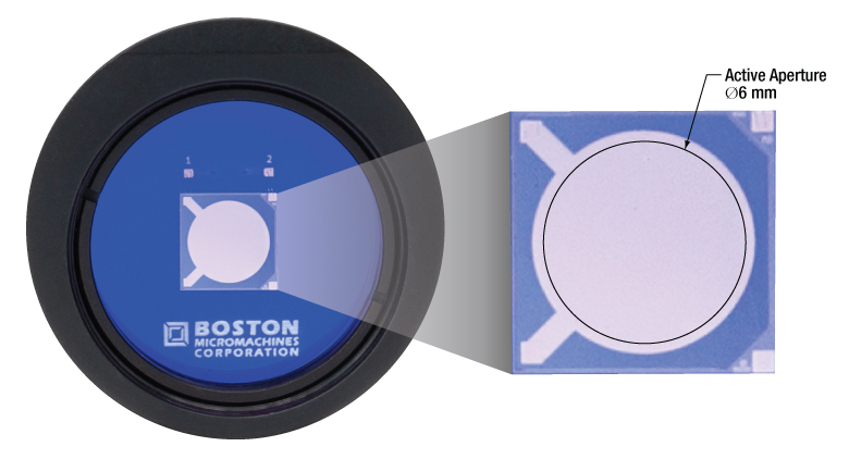
Front of MEMS Grating Modulator
Features
- Reflective Gold Coating with Near Zero Dispersion
- 600 - 1100 nm Operating Range
- Frequency Range of 0 - 200 kHz
- Polarization Independent Operation
- Response Times of Less Than 2.5 μs
- Continuous Sustained Operation
- Large Clear Active Aperture of Ø6.0 mm
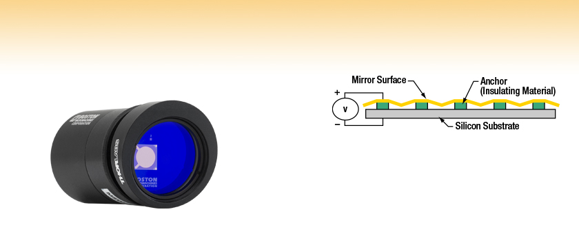
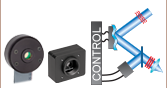
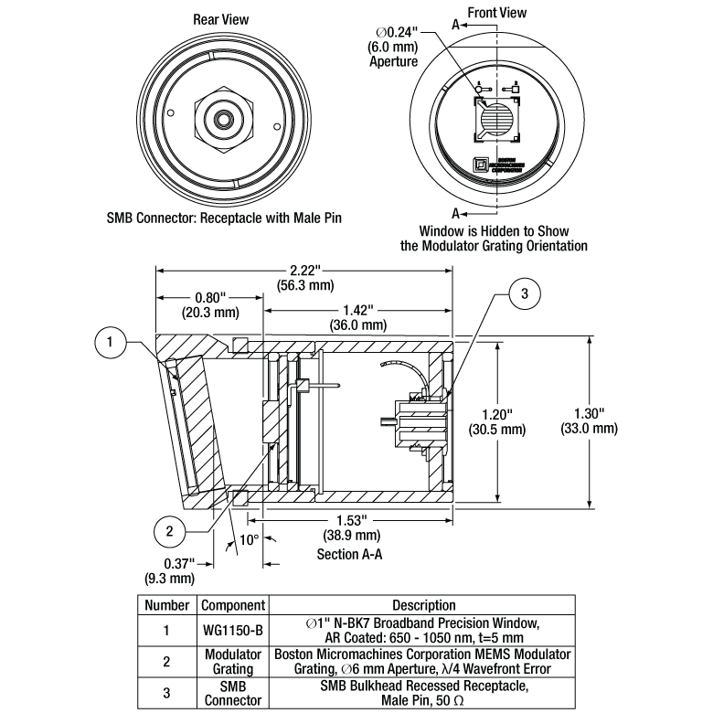
This Micro-Electro-Mechanical (MEMS) Grating Modulator, manufactured by our strategic partner Boston Micromachines Corporation, has controllable groove depth which modulates intensity. This reflective, low-modulation MEMS grating acts as a metallic plane mirror when no voltage is applied and becomes a deformable reflective one-dimensional grating with controllable groove depth when voltage is applied for advanced optical control. The circular Ø6.0 mm gold coated region shown in the figure on the right is the active aperture that consists of an array of electrostatic actuators. The grating modulator can achieve a high extinction ratio of 200:1 in the 600 - 1100 nm wavelength range at a 10° angle of incidence (AOI) or less (see the Graphs tab for more information). A 10° angled WG11050-B window that is AR coated for the 650 - 1050 nm range protects the device.
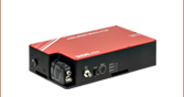
An external high-voltage power source, such as the HVA200 High-Voltage Amplifier (not included), is needed to drive the grating modulator. The maximum operating voltage varies from device to device but will not exceed 200 V. Each unit is labeled with the maximum operating voltage and ships with a data sheet that notes the optimal voltage settings. To connect a voltage source, connect a cable to the SMB male connector on the housing rear. Electrically, the modulator behaves as a capacitor with a capacitance of 250 pF. Each wavelength of interest for the grating requires a different extinction voltage which can be adjusted by the user. The modulator has a frequency range of up to 200 kHz with full modulation and higher speeds with partial modulation. Use the modulator to replace a pockels cell or as a substitute for an acousto-optic or electro-optic modulator for applications that require higher throughput.
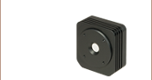
A Ø1" lens tube houses the grating modulator, allowing it to be mounted using our SM1RC(/M) slip ring, SM1TC clamp, or other mounts for Ø1" lens tubes. Alternatively, the SM2A21 adapter can be used to mount mounted the modulator in the KM200 Ø2" Precision Kinematic Mirror Mount. and easily mounted Please see the Specs tab for more information on the housing dimensions.
Please note that these products are statically sensitive; always handle in an electrostatically sensitive environment and wear a grounded ESD wrist strap.
Thorlabs also offers Fast Laser Power Modulators for Two-Photon Microscopy that provide an integrated solution to enable high-speed intensity modulation and beam attenuation optimized for imaging applications.
Diffracted Beam Elimination
Since the grating diffracts incident light, the pattern spreads out continuously. To eliminate diffracted orders from entering the beam path, an iris (not included) is recommended. If the beam size is still too large, place the optical elements far away from the grating to prevent overlap of the non-diffracted and diffracted beams.
Warning on Voltage Sources
The grating modulator can be operated using any high-voltage power source that is free from noise that exceeds the maximum rated voltage. Before use, verify that the control voltages of the power source are well conditioned and produce no voltage spikes, which can irreversibly damage the device if the maximum device voltage is exceeded. If possible, install a switch between the voltage source and the unit to disconnect the grating from the voltage source whenever a change in conditions is necessary.
| Item # | MGR6N |
|---|---|
| Housing Dimensions (D x L) | Ø1.30" x 2.22" |
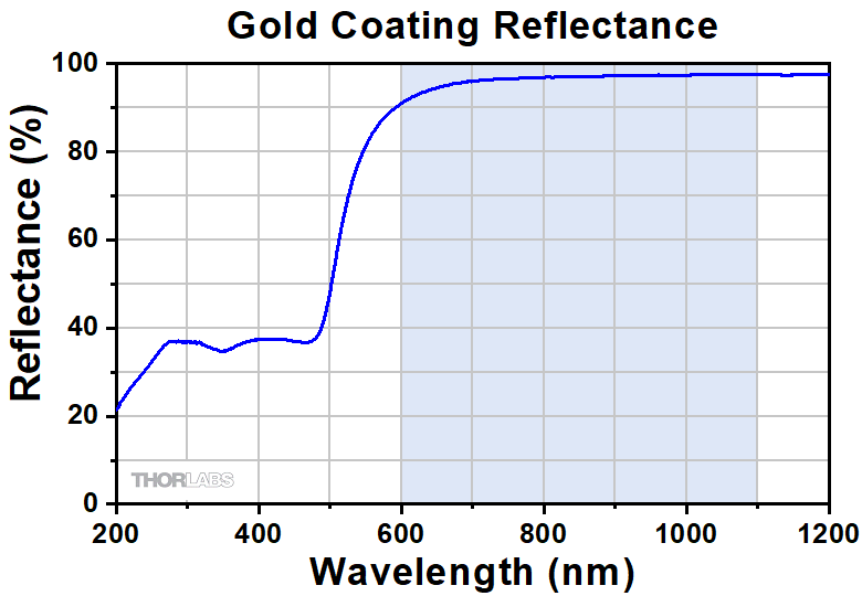
| Reflective Coating (Click for Plot) | Gold |
| Frequency Range | 0 to 200 kHz |
| Rise/Fall Time: 90% - 10% | <2.5 μs |
| Rise/Fall Time: 97% - 3% | <4 μs |
| Peak Extinction Ratioa | 200:1 at 632 nm |
| Optimal Wavelength Range | 600 - 1100 nm |
| Angle-of-Incidence for Peak Extinction | <10° (Lateral Incident Angle) |
| Maximum Extinction Frequency Limit, -3 dBb | 100 kHz |
| Active Aperture | Ø6.0 mm |
| Total Reflected Wavefront Error (P-V) | λ/4 |
| Maximum Operating Voltage (Device Dependent)c |
<200 V |
| Maximum Extinction Voltage (Device Dependent; Angle Dependent Above 10°)d |
See Graphs Tab for Typical Performance |
| Protective Window | |
| Item # | WG11050-B |
| Angle | 10° |
| Substrate | N-BK7e |
| Diameter | 1" |
| Thickness | 5 mm |
Click to Enlarge
Dimensions for the MEMS Grating Modulator
Performance Graphs
This data reflects the typical performance of our MEMS deformable grating and is presented for reference only. The guaranteed specifications are shown in the Specs tab.
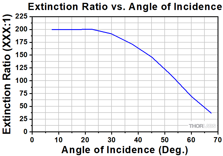
Click to Enlarge
Click Here for Raw Data
The graph above shows the extinction for various angles of incidence on a typical device. For maximum extinction and reduced beam distortion, the angle should be below 20°. For higher angles of incidence, the voltage should be re-optimized.
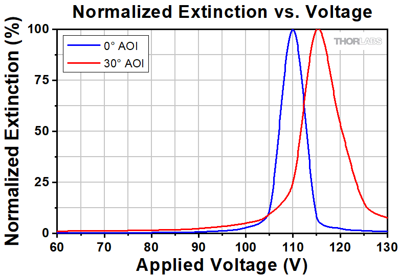
Click to Enlarge
Click Here for Raw Data
The graph above shows the typical extinction versus voltage at 632 nm. The optical extinction varies with angle of incidence as well as from device to device. Each unit ships with a data sheet that notes the optimal voltage settings and associated extinction ratios for normal incidence.

Click to Enlarge
The graph above shows the reflectance of the gold coating. The blue shaded region indicates the specified wavelength range for which the performance is guaranteed. Performance outside the shaded regions will vary from lot to lot.

Click to Enlarge
The graph above shows the typical deflection of a deformable grating as a function of voltage. Ensure that the maximum rated voltage is not exceeded under any circumstances or the device will be irreparably damaged.
| Posted Comments: | |
Florent Haiss
(posted 2021-11-01 11:57:44.28) Would this device (MGR6N) also work with at 1300 nm (2 MHz, 50fs, 3W laser) after replacing the front window for a C coating window? YLohia
(posted 2021-11-12 04:50:11.0) Hello, thank you for contacting Thorlabs. Unfortunately, the change in the window's AR coating alone will not work. The issue is that it’s difficult to reach full extinction over a reasonable distance. We are in the process of releasing a 1300 nm version of our OM6N modulator, based on a similar technology. That being said, we don't have an exact release date scheduled for this product yet. We will reach out to you directly to discuss further. |