 Products Home / Technical Resources / Insights / Device Behavior Insights / Thermal Rollover Effect in Quantum and Interband Cascade Lasers (QCLs and ICLs)
Thermal Rollover Effect in Quantum and Interband Cascade Lasers (QCLs and ICLs)


Please Wait
QCLs and ICLs: Operating Limits and Thermal Rollover
Click to Enlarge
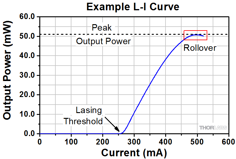
Figure 1: This example of an L-I curve for a QCL laser illustrates the typical non-linear slope and rollover region exhibited by QCL and ICL lasers. Operating parameters determine the heat load carried by the lasing region, which influences the peak output power. This laser was installed in a temperature controlled mount set to 25 °C.

Click to Enlarge
Figure 2: This set of L-I curves for a QCL laser illustrates that the mount temperature can affect the peak operating temperature, but that using a temperature controlled mount does not remove the danger of applying a driving current large enough to exceed the rollover point and risk damaging the laser.
The light vs. driving current (L-I) curves measured for quantum and interband cascade Lasers (QCLs and ICLs) include a rollover region, which is enclosed by the red box in Figure 1.
The rollover region includes the peak output power of the laser, which corresponds to a driving current of just under 500 mA in this example. Applying higher drive currents risks damaging the laser.
Laser Operation
These lasers operate by forcing electrons down a controlled series of energy steps, which are created by the laser's semiconductor layer structure and an applied bias voltage. The driving current supplies the electrons.
An electron must give up some of its energy to drop down to a lower energy level. When an electron descends one of the laser's energy steps, the electron loses energy in the form of a photon. But, the electron can also lose energy by giving it to the semiconductor material as heat, instead of emitting a photon.
Heat Build Up
Lasers are not 100% efficient in forcing electrons to surrender their energy in the form of photons. The electrons that lose their energy as heat cause the temperature of the lasing region to increase.
Conversely, heat in the lasing region can be absorbed by electrons. This boost in energy can scatter electrons away from the path leading down the laser's energy steps. Later, scattered electrons typically lose energy as heat, instead of as photons.
As the temperature of the lasing region increases, more electrons are scattered, and a smaller fraction of them produce light instead of heat. Rising temperatures can also result in changes to the laser's energy levels that make it harder for electrons to emit photons. These processes work together to increase the temperature of the lasing region and to decrease the efficiency with which the laser converts current to laser light.
Operating Limits are Determined by the Heat Load
Ideally, the slope of the L-I curve would be linear above the threshold current, which is around 270 mA in Figure 1. Instead, the slope decreases as the driving current increases, which is due to the effects from the rising temperature of the lasing region. Rollover occurs when the laser is no longer effective in converting additional current to laser light. Instead, the extra driving creates only heat. When the current is high enough, the strong localized heating of the laser region will cause the laser to fail.
A temperature controlled mount is typically necessary to help manage the temperature of the lasing region. But, since the thermal conductivity of the semiconductor material is not high, heat can still build up in the lasing region. As illustrated in Figure 2, the mount temperature affects the peak optical output power but does not prevent rollover.
The maximum drive current and the maximum optical output power of QCLs and ICLs depend on the operating conditions, since these determine the heat load of the lasing region.
|
Looking for more Insights? |
Date of Last Edit: Dec. 4, 2019 |
| Posted Comments: | |
| No Comments Posted |