Using a Chopper Wheel to Measure Laser Beam Diameter


Please Wait
Beam Size Measurement Using a Chopper Wheel

Click to Enlarge
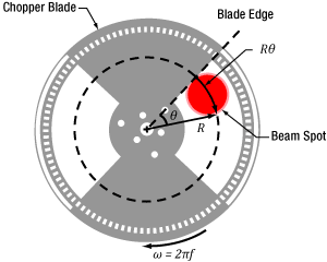
Figure 2: The blade traces an arc length of Rθ through the center of the beam and has a angular rotation rate of  f. The chopper wheel shown is MC1F2.

Click to Enlarge
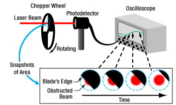
Figure 1: An approximate measurement of beam size can be found using the illustrated setup. As the blade of the chopper wheel passes through the beam, an S-curve is traced out on the oscilloscope.

Click to Enlarge
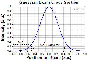
Figure 4: The diameter of a Gaussian beam is often given in terms of the 1/e2 full width.

Click to Enlarge
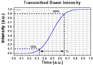
Figure 3: Rise time (tr ) of the intensity signal is typically measured between the 10% and 90% points on the curve. The rise time depends on the wheel's rotation rate and the beam diameter.
Camera and scanning-slit beam profilers are tools for characterizing beam size and shape, but these instruments cannot provide an accurate measurement if the beam size is too small or the wavelength is outside of the operating range.
A chopper wheel, photodetector, and oscilloscope can provide an approximate measurement of the beam size (Figure 1). As the rotating chopper wheel's blade passes through the beam, an S-shaped trace is displayed on the oscilloscope.
When the blade sweeps through the angle θ , the rise or fall time of the S-curve is proportional to the size of the beam along the direction of the blade's travel (Figure 2). A point on the blade located a distance R from the center of the wheel sweeps through an arc length (Rθ ) that is approximately equal to the size of the beam along this direction.
To make this beam size measurement, the combined response of the detector and oscilloscope should be much faster than the signal's rate of change.
Example: S-Curve with Rising Edge
The angle  ftr )
ftr ) ftr )
ftr )

includes a factor of 1.56, which accounts for the portion of the beam measured between the 10% and 90% intensity points being smaller than the 1/e2 beam diameter.
|
Looking for more Insights? |
Date of Last Edit: June 22, 2021 |
| Posted Comments: | |
Graham Wilson
(posted 2021-06-14 14:45:43.763) Hi,
I was reading your article on Beam Size Measurement Using a Chopper Wheel. The article has a formula that is
essentially D = 0.64 d where d is the distance traveled by the
chopper edge in the rise-time (10% to 90%).
[In the article d=2 pi f t_r R]
This 0.64 factor did not look correct but there were no direct references.
For a Gaussian beam the 10%-90% distance, d,
should correspond to 2.563 standard deviations (sigma). The central 80% (10%, 90%) of a normal distribution is contained within +- 1.2816 standard deviations.
So if one wants beam diameter,
D = 4 sigma = 4 * (d/2.563 ) = 1.561 d = (d / 0.641).
So instead of D=0.64 d it should be D = d/0.64, or probably easier
to comprehend if written as D = 1.56 d. This is quite a big mistake, namely the inferred 1/e2 diameter should be a factor of 1.56/0.64=2.44 bigger!
thanks,
Graham Wilson (please acknowledge receipt). cdolbashian
(posted 2021-06-25 09:07:09.0) Thank you for being so attentive to the content of our articles! We aim for these to be concise, informative, and most importantly, factually correct. We truly appreciate the time you took to verify the information on our page, and we have corrected the error which you identified. The article should be free of errors now, thanks to you! |
 Products Home
 Using a Chopper to Measure Beam Diameter