 Products Home / Technical Resources / Insights / Lab Practices Insights / Clamping Forks Can Cause Bowing of the Optical Table Surface
Clamping Forks Can Cause Bowing of the Optical Table Surface


Please Wait
Optical Tables: Clamping Forks and Distortion of the Table's Surface
Click to Enlarge
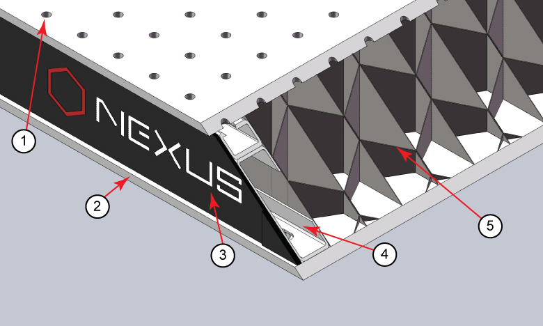
Figure 1: The construction of a Nexus table / breadboard includes a (1) top skin, (2) bottom skin, (3) side finishing trim, (4) side panels, and (5) honeycomb core. The stainless steel top and bottom skins are 5 mm thick.
Click to Enlarge
Figure 3: Torqueing the screw creates a force that pulls up on the table's top skin. The lifted skin tilts the mounting surface and can induce angular deviation of the object. This effect is exaggerated in the above image for illustrative purposes.
Click to Enlarge
Figure 2: A standard clamping fork, such as the CL5A, contacts the table along only one edge. The opposite edge is in contact with the object to be secured. A bridge forms between the two. The screw that applies the clamping force is not shown.
Click to Enlarge
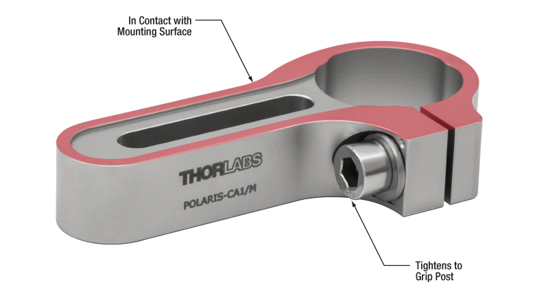
Figure 4: The POLARIS-CA1/M clamping arm has a slot that accepts a mounting screw, a separate screw that applies a clamping force to an installed post, and identical top and bottom surfaces. Since a nearly continuous track around the surface of the clamping arm (shown highlighted in red) is in contact with the mounting surface, clamping arms cause negligible bridging effects.
Clamping forks are more rigid than the mounting surface of composite optical tables. It might be expected that the spine of the clamping fork would bend with the force exerted by the screw as the torque is increased. Instead, the screw will pull the skin of the table up and out of flat before the clamping fork deforms. Due to this, clamping forks should be used with care when securing components to optical tables. Clamping arms, which are discussed in the following, are alternatives to clamping forks that are less likely to deform the table's mounting surface.
Optical Table Construction
Optical tables and breadboards with composite construction (Figure 1) are designed to be rigid while providing vibration damping. The 5 mm thick, stainless steel top skin is manufactured to be flat, but a localized force can deform it. When the top skin is deformed, optical components will not sit flat, and optical system alignment and performance can be negatively affected.
Clamping Forks
Standard clamping forks are installed with one edge placed on the table's surface and the opposite edge on the object (Figure 2). Between these two edges, there is clearance between the bottom of the clamp and the surface of the table. This bridge makes it possible to use a single screw to both secure the clamp to the table and exert a holding force on the object.
When the clamp is secured by torqueing the screw, the screw pulls up on the top skin of the table (Figure 3).
As the torque on the screw increases, the top skin of the table rises. Not only does pulling up on the table surface risk permanently damaging the table, this can also disturb the alignment of the optical component the clamp is being used to secure. By lifting the table's skin, the mounting surface under the clamped object tilts.
Clamping Arms
Clamping arms, such as the POLARIS-CA1/M, shown in Figure 4, are designed to secure a post while minimally deforming the mounting surface.
The clamping arm in Figure 4 differs from clamping forks in two significant ways. One is the surface area that makes contact with the optical table, which is highlighted in red, and the other is the method used to secure the post.
The area in contact with the optical table makes a nearly continuous loop around the base of the clamp. The contact area is flat and flush with the table when the clamp is installed. The only break in the loop is a narrow slot in the vise used to grip the post.
This design uses two screws, instead of the clamping fork's single screw. One screw (not shown) secures the clamp to the table, and the other (indicated) is tightened to grip the post. Since one screw is not required to perform both tasks, it is not necessary for this clamping arm to form a bridge between the clamped object and the optical table.
Although the contact area is a loop, and not a solid surface, this clamp causes negligible distortion of the mounting surface. This is due to the open area inside the contact surface being narrow and surrounded by the sides of the clamp, which resist the force pulling up on the table.
|
Looking for more Insights? |
Date of Last Edit: Dec. 4, 2019 |
| Posted Comments: | |
| No Comments Posted |