 Products Home / Optical Elements / Optical Mirrors / Broadband Dielectric Mirrors / Fused Silica Broadband Dielectric Mirrors
Fused Silica Broadband Dielectric Mirrors
- Excellent Reflectance Over Specified Wavelength Ranges and Angles of Incidence
- Ravg > 99% for S- and P-Polarizations
- AOI: 0º - 45º
BB05-E03
Ø1/2"
BB07-E03
Ø19.0 mm
BB1-E01
Ø1"
BB2-E04
Ø2"
BBSQ2-E03
2" x 2"
BBSQ1-E03
1" x 1"
BBSQ05-E03
1/2" x 1/2"
BB3-E02
Ø3"
BB4-E03
Ø4"
BB03-E03
Ø7.0 mm


Please Wait
Click to Enlarge
Back View
Features
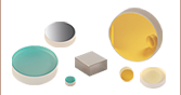
- Round Mirror Diameters: 7.0 mm, 1/2", 19.0 mm, 1", 2", 3", or 4"
- Square Mirror Edge Lengths: 1/2", 1", or 2"
- Four Broadband Coating Options
- 350 - 400 nm (Not Stocked with Ø7.0 mm, Ø3", Ø4", or Square Substrates)
- 400 - 750 nm
- 750 - 1100 nm
- 1280 - 1600 nm (Not Stocked with Ø3", Ø4", or Square Substrates)
- Fused Silica Substrates
- Ravg > 99% for S- and P- Polarization for Angles of Incidence from 0 to 45°
- Designed for CW and Nanosecond Lasers
Thorlabs' Fused Silica Broadband Dielectric Mirrors offer excellent reflectance over four different spectral ranges. Due to run-to-run coating variations, please note that the specified spectral range listed for each coating is smaller than the actual spectral region over which the mirror is effective. The plots shown under the Reflectance Plots tab show the performance characteristics of a typical mirror near the edges of its effective spectral range.
The round Ø1/2", Ø1", and Ø2" mirrors are also available in packs of 10 at a discount over the individual price.
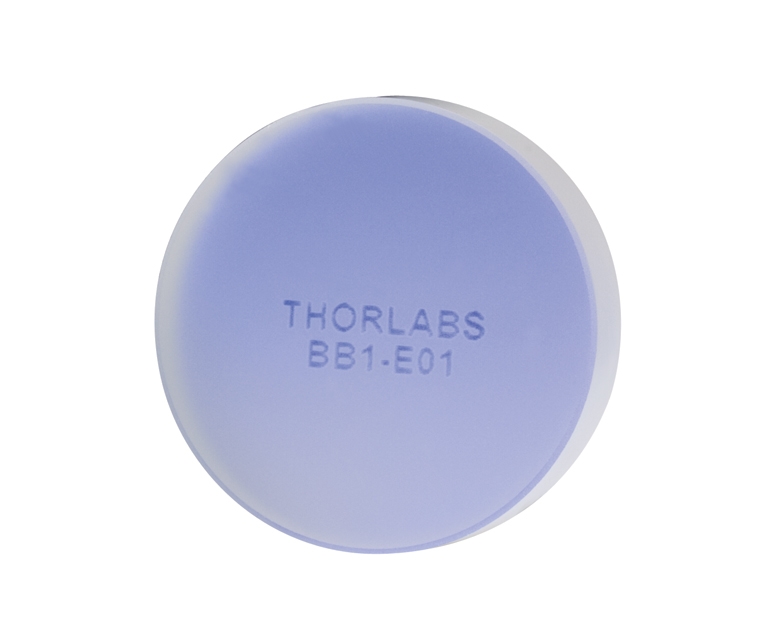
As seen in the photo to the right, the back of each mirror is engraved with its respective part number, with the exception of our Ø7.0 mm mirrors.
The plot below is the reflectance of each broadband mirror coating in the BB series as a function of wavelength for unpolarized light incident at an angle of 6° or 8°. This choice of incident angle was due to the measurement limitations at 0°; however the plots closely represent reflectance at 0°. More detailed plots that also include polarization information are available under the Reflectance Plots tab.
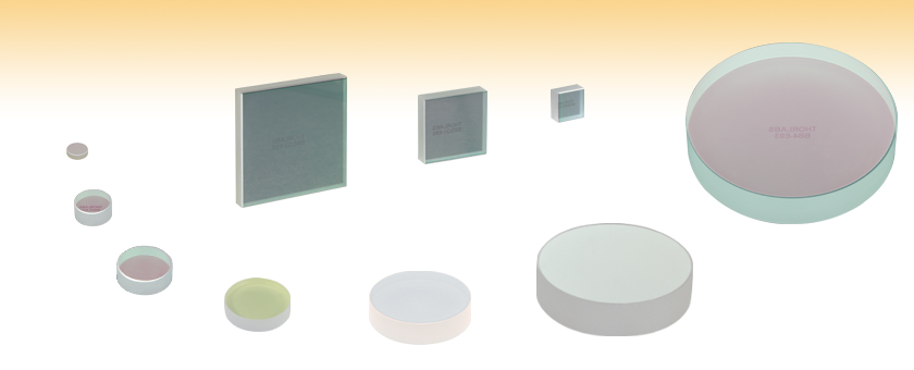
For applications that would benefit from having a small portion of the beam transmitted through the optic, consider one of our backside polished mirrors. Alternatively, if you need a mirror that bridges the spectral range between two different coatings, consider a mirror with a metallic coating or, if the mirrors are needed in sufficient quantity, contact Technical Support for a custom mirror quotation. Please note that these mirrors are not suitable for ultrafast applications; see our low GDD ultrafast mirrors for picosecond and femtosecond pulsed lasers.
| Specifications | ||
|---|---|---|
| Material | Fused Silica | |
| Surface Flatness | λ/10 at 633 nm | |
| Surface Quality | 10-5 Scratch-Dig | |
| Back Surface | Fine Ground | |
| Clear Aperture | >85% of Diameter (Round) >85% of Dimension (Square) |
|
| Parallelism | ≤3 arcmin | |
| Thickness | Ø7.0 mm Optics | 2.0 mm (0.08") |
| Ø1/2" Optics | 6.0 mm (0.24") | |
| 1/2" x 1/2" Optics | 6.0 mm (0.24") | |
| Ø19 mm Optics | 6.0 mm (0.24") | |
| Ø1" Optics | 6.0 mm (0.24") | |
| 1" x 1" Optics | 6.0 mm (0.24") | |
| Ø2" Optics | 12.0 mm (0.47") | |
| 2" x 2" Optics | 6.0 mm (0.24") | |
| Ø3" Optics | 19.1 mm (0.75") | |
| Ø4" Optics | 19.1 mm (0.75") | |
| Thickness Tolerance | ±0.2 mm | |
| Diameter Tolerance | +0.0 mm / -0.1 mm | |
| Coating Specifications | ||
|---|---|---|
| Coating Designation | Reflectance (Click for Graph) | |
| -E01 | Ravg >99% (350 - 400 nm) | |
| -E02 | Ravg >99% (400 - 750 nm) | |
| -E03 | Ravg >99% (750 - 1100 nm) | |
| -E04 | Ravg >99% (1280 - 1600 nm) | |
| Coating Designation | Damage Threshold | |
| -E01 | Pulse | 1 J/cm2 (355 nm, 10 ns, 10 Hz, Ø0.373 mm) |
| -E02 | Pulse | 0.25 J/cm2 (532 nm, 10 ns, 10 Hz, Ø0.803 mm) |
| CWa,b | 550 W/cm (532 nm, Ø1.000 mm) | |
| -E03 | Pulse | 0.205 J/cm2 (800 nm, 99 fs, 1 kHz, Ø0.166 mm) 1 J/cm2 (810 nm, 10 ns, 10 Hz, Ø0.133 mm) 0.5 J/cm2 (1064 nm, 10 ns, 10 Hz, Ø0.433 mm) |
| CWa,b | 10 kW/cm (1070 nm, Ø0.971 mm) | |
| -E04 | Pulse | 2.5 J/cm2 (1542 nm, 10 ns, 10 Hz, Ø0.181 mm) |
| CWa,b | 350 W/cm (1540 nm, Ø1.030 mm) | |
These plots show the reflectance of each of our four dielectric coatings for a typical coating run. The shaded region in each graph denotes the spectral range over which the coating is highly reflective. Due to variations in each run, this recommended spectral range is narrower than the actual range over which the optic will be highly reflective. If you have any concerns about the interpretation of this data, please contact Tech Support. For applications that require a mirror that bridges the spectral range between two dielectric coatings, please consider a metallic mirror.
-E01 Coating (350 - 400 nm)
Excel Spreadsheet with Raw Data for -E01 Coating, 6° and 45° AOI
-E02 Coating (400 - 750 nm)
Excel Spreadsheet with Raw Data for -E02 Coating, 8° and 45° AOI
-E03 Coating (750 - 1100 nm)
Excel Spreadsheet with Raw Data for -E03 Coating, 6° and 45° AOI
-E04 Coating (1280 - 1600 nm)
Excel Spreadsheet with Raw Data for -E04 Coating, 6° and 45° AOI
| Damage Threshold Specifications | ||
|---|---|---|
| Coating Designation (Item # Suffix) |
Type | Damage Threshold |
| -E01 | Pulsed | 1 J/cm2 (355 nm, 10 ns, 10 Hz, Ø0.373 mm) |
| -E02 | Pulsed | 0.25 J/cm2 (532 nm, 10 ns, 10 Hz, Ø0.803 mm) |
| CWa,b | 550 W/cm (532 nm, Ø1.000 mm) | |
| -E03 | Pulsed | 0.205 J/cm2 (800 nm, 99 fs, 1 kHz, Ø0.166 mm) 1 J/cm2 (810 nm, 10 ns, 10 Hz, Ø0.133 mm) 0.5 J/cm2 (1064 nm, 10 ns, 10 Hz, Ø0.433 mm) |
| CWa,b | 10 kW/cm (1070 nm, Ø0.971 mm) | |
| -E04 | Pulsed | 2.5 J/cm2 (1542 nm, 10 ns, 10 Hz, Ø0.181 mm) |
| CWa,b | 350 W/cm (1540 nm, Ø1.030 mm) | |
Damage Threshold Data for Thorlabs' Broadband Dielectric Mirrors
The specifications to the right are measured data for Thorlabs' broadband dielectric mirrors. Damage threshold specifications are constant for a given coating type, regardless of the size and shape of the mirror.
Laser Induced Damage Threshold Tutorial
The following is a general overview of how laser induced damage thresholds are measured and how the values may be utilized in determining the appropriateness of an optic for a given application. When choosing optics, it is important to understand the Laser Induced Damage Threshold (LIDT) of the optics being used. The LIDT for an optic greatly depends on the type of laser you are using. Continuous wave (CW) lasers typically cause damage from thermal effects (absorption either in the coating or in the substrate). Pulsed lasers, on the other hand, often strip electrons from the lattice structure of an optic before causing thermal damage. Note that the guideline presented here assumes room temperature operation and optics in new condition (i.e., within scratch-dig spec, surface free of contamination, etc.). Because dust or other particles on the surface of an optic can cause damage at lower thresholds, we recommend keeping surfaces clean and free of debris. For more information on cleaning optics, please see our Optics Cleaning tutorial.
Testing Method
Thorlabs' LIDT testing is done in compliance with ISO/DIS 11254 and ISO 21254 specifications.
First, a low-power/energy beam is directed to the optic under test. The optic is exposed in 10 locations to this laser beam for 30 seconds (CW) or for a number of pulses (pulse repetition frequency specified). After exposure, the optic is examined by a microscope (~100X magnification) for any visible damage. The number of locations that are damaged at a particular power/energy level is recorded. Next, the power/energy is either increased or decreased and the optic is exposed at 10 new locations. This process is repeated until damage is observed. The damage threshold is then assigned to be the highest power/energy that the optic can withstand without causing damage. A histogram such as that below represents the testing of one BB1-E02 mirror.

The photograph above is a protected aluminum-coated mirror after LIDT testing. In this particular test, it handled 0.43 J/cm2 (1064 nm, 10 ns pulse, 10 Hz, Ø1.000 mm) before damage.

| Example Test Data | |||
|---|---|---|---|
| Fluence | # of Tested Locations | Locations with Damage | Locations Without Damage |
| 1.50 J/cm2 | 10 | 0 | 10 |
| 1.75 J/cm2 | 10 | 0 | 10 |
| 2.00 J/cm2 | 10 | 0 | 10 |
| 2.25 J/cm2 | 10 | 1 | 9 |
| 3.00 J/cm2 | 10 | 1 | 9 |
| 5.00 J/cm2 | 10 | 9 | 1 |
According to the test, the damage threshold of the mirror was 2.00 J/cm2 (532 nm, 10 ns pulse, 10 Hz, Ø0.803 mm). Please keep in mind that these tests are performed on clean optics, as dirt and contamination can significantly lower the damage threshold of a component. While the test results are only representative of one coating run, Thorlabs specifies damage threshold values that account for coating variances.
Continuous Wave and Long-Pulse Lasers
When an optic is damaged by a continuous wave (CW) laser, it is usually due to the melting of the surface as a result of absorbing the laser's energy or damage to the optical coating (antireflection) [1]. Pulsed lasers with pulse lengths longer than 1 µs can be treated as CW lasers for LIDT discussions.
When pulse lengths are between 1 ns and 1 µs, laser-induced damage can occur either because of absorption or a dielectric breakdown (therefore, a user must check both CW and pulsed LIDT). Absorption is either due to an intrinsic property of the optic or due to surface irregularities; thus LIDT values are only valid for optics meeting or exceeding the surface quality specifications given by a manufacturer. While many optics can handle high power CW lasers, cemented (e.g., achromatic doublets) or highly absorptive (e.g., ND filters) optics tend to have lower CW damage thresholds. These lower thresholds are due to absorption or scattering in the cement or metal coating.

LIDT in linear power density vs. pulse length and spot size. For long pulses to CW, linear power density becomes a constant with spot size. This graph was obtained from [1].

Pulsed lasers with high pulse repetition frequencies (PRF) may behave similarly to CW beams. Unfortunately, this is highly dependent on factors such as absorption and thermal diffusivity, so there is no reliable method for determining when a high PRF laser will damage an optic due to thermal effects. For beams with a high PRF both the average and peak powers must be compared to the equivalent CW power. Additionally, for highly transparent materials, there is little to no drop in the LIDT with increasing PRF.
In order to use the specified CW damage threshold of an optic, it is necessary to know the following:
- Wavelength of your laser
- Beam diameter of your beam (1/e2)
- Approximate intensity profile of your beam (e.g., Gaussian)
- Linear power density of your beam (total power divided by 1/e2 beam diameter)
Thorlabs expresses LIDT for CW lasers as a linear power density measured in W/cm. In this regime, the LIDT given as a linear power density can be applied to any beam diameter; one does not need to compute an adjusted LIDT to adjust for changes in spot size, as demonstrated by the graph to the right. Average linear power density can be calculated using the equation below.

The calculation above assumes a uniform beam intensity profile. You must now consider hotspots in the beam or other non-uniform intensity profiles and roughly calculate a maximum power density. For reference, a Gaussian beam typically has a maximum power density that is twice that of the uniform beam (see lower right).
Now compare the maximum power density to that which is specified as the LIDT for the optic. If the optic was tested at a wavelength other than your operating wavelength, the damage threshold must be scaled appropriately. A good rule of thumb is that the damage threshold has a linear relationship with wavelength such that as you move to shorter wavelengths, the damage threshold decreases (i.e., a LIDT of 10 W/cm at 1310 nm scales to 5 W/cm at 655 nm):

While this rule of thumb provides a general trend, it is not a quantitative analysis of LIDT vs wavelength. In CW applications, for instance, damage scales more strongly with absorption in the coating and substrate, which does not necessarily scale well with wavelength. While the above procedure provides a good rule of thumb for LIDT values, please contact Tech Support if your wavelength is different from the specified LIDT wavelength. If your power density is less than the adjusted LIDT of the optic, then the optic should work for your application.
Please note that we have a buffer built in between the specified damage thresholds online and the tests which we have done, which accommodates variation between batches. Upon request, we can provide individual test information and a testing certificate. The damage analysis will be carried out on a similar optic (customer's optic will not be damaged). Testing may result in additional costs or lead times. Contact Tech Support for more information.
Pulsed Lasers
As previously stated, pulsed lasers typically induce a different type of damage to the optic than CW lasers. Pulsed lasers often do not heat the optic enough to damage it; instead, pulsed lasers produce strong electric fields capable of inducing dielectric breakdown in the material. Unfortunately, it can be very difficult to compare the LIDT specification of an optic to your laser. There are multiple regimes in which a pulsed laser can damage an optic and this is based on the laser's pulse length. The highlighted columns in the table below outline the relevant pulse lengths for our specified LIDT values.
Pulses shorter than 10-9 s cannot be compared to our specified LIDT values with much reliability. In this ultra-short-pulse regime various mechanics, such as multiphoton-avalanche ionization, take over as the predominate damage mechanism [2]. In contrast, pulses between 10-7 s and 10-4 s may cause damage to an optic either because of dielectric breakdown or thermal effects. This means that both CW and pulsed damage thresholds must be compared to the laser beam to determine whether the optic is suitable for your application.
| Pulse Duration | t < 10-9 s | 10-9 < t < 10-7 s | 10-7 < t < 10-4 s | t > 10-4 s |
|---|---|---|---|---|
| Damage Mechanism | Avalanche Ionization | Dielectric Breakdown | Dielectric Breakdown or Thermal | Thermal |
| Relevant Damage Specification | No Comparison (See Above) | Pulsed | Pulsed and CW | CW |
When comparing an LIDT specified for a pulsed laser to your laser, it is essential to know the following:

LIDT in energy density vs. pulse length and spot size. For short pulses, energy density becomes a constant with spot size. This graph was obtained from [1].
- Wavelength of your laser
- Energy density of your beam (total energy divided by 1/e2 area)
- Pulse length of your laser
- Pulse repetition frequency (prf) of your laser
- Beam diameter of your laser (1/e2 )
- Approximate intensity profile of your beam (e.g., Gaussian)
The energy density of your beam should be calculated in terms of J/cm2. The graph to the right shows why expressing the LIDT as an energy density provides the best metric for short pulse sources. In this regime, the LIDT given as an energy density can be applied to any beam diameter; one does not need to compute an adjusted LIDT to adjust for changes in spot size. This calculation assumes a uniform beam intensity profile. You must now adjust this energy density to account for hotspots or other nonuniform intensity profiles and roughly calculate a maximum energy density. For reference a Gaussian beam typically has a maximum energy density that is twice that of the 1/e2 beam.
Now compare the maximum energy density to that which is specified as the LIDT for the optic. If the optic was tested at a wavelength other than your operating wavelength, the damage threshold must be scaled appropriately [3]. A good rule of thumb is that the damage threshold has an inverse square root relationship with wavelength such that as you move to shorter wavelengths, the damage threshold decreases (i.e., a LIDT of 1 J/cm2 at 1064 nm scales to 0.7 J/cm2 at 532 nm):

You now have a wavelength-adjusted energy density, which you will use in the following step.
Beam diameter is also important to know when comparing damage thresholds. While the LIDT, when expressed in units of J/cm², scales independently of spot size; large beam sizes are more likely to illuminate a larger number of defects which can lead to greater variances in the LIDT [4]. For data presented here, a <1 mm beam size was used to measure the LIDT. For beams sizes greater than 5 mm, the LIDT (J/cm2) will not scale independently of beam diameter due to the larger size beam exposing more defects.
The pulse length must now be compensated for. The longer the pulse duration, the more energy the optic can handle. For pulse widths between 1 - 100 ns, an approximation is as follows:

Use this formula to calculate the Adjusted LIDT for an optic based on your pulse length. If your maximum energy density is less than this adjusted LIDT maximum energy density, then the optic should be suitable for your application. Keep in mind that this calculation is only used for pulses between 10-9 s and 10-7 s. For pulses between 10-7 s and 10-4 s, the CW LIDT must also be checked before deeming the optic appropriate for your application.
Please note that we have a buffer built in between the specified damage thresholds online and the tests which we have done, which accommodates variation between batches. Upon request, we can provide individual test information and a testing certificate. Contact Tech Support for more information.
[1] R. M. Wood, Optics and Laser Tech. 29, 517 (1998).
[2] Roger M. Wood, Laser-Induced Damage of Optical Materials (Institute of Physics Publishing, Philadelphia, PA, 2003).
[3] C. W. Carr et al., Phys. Rev. Lett. 91, 127402 (2003).
[4] N. Bloembergen, Appl. Opt. 12, 661 (1973).

In order to illustrate the process of determining whether a given laser system will damage an optic, a number of example calculations of laser induced damage threshold are given below. For assistance with performing similar calculations, we provide a spreadsheet calculator that can be downloaded by clicking the button to the right. To use the calculator, enter the specified LIDT value of the optic under consideration and the relevant parameters of your laser system in the green boxes. The spreadsheet will then calculate a linear power density for CW and pulsed systems, as well as an energy density value for pulsed systems. These values are used to calculate adjusted, scaled LIDT values for the optics based on accepted scaling laws. This calculator assumes a Gaussian beam profile, so a correction factor must be introduced for other beam shapes (uniform, etc.). The LIDT scaling laws are determined from empirical relationships; their accuracy is not guaranteed. Remember that absorption by optics or coatings can significantly reduce LIDT in some spectral regions. These LIDT values are not valid for ultrashort pulses less than one nanosecond in duration.
A Gaussian beam profile has about twice the maximum intensity of a uniform beam profile.
CW Laser Example
Suppose that a CW laser system at 1319 nm produces a 0.5 W Gaussian beam that has a 1/e2 diameter of 10 mm. A naive calculation of the average linear power density of this beam would yield a value of 0.5 W/cm, given by the total power divided by the beam diameter:
However, the maximum power density of a Gaussian beam is about twice the maximum power density of a uniform beam, as shown in the graph to the right. Therefore, a more accurate determination of the maximum linear power density of the system is 1 W/cm.
An AC127-030-C achromatic doublet lens has a specified CW LIDT of 350 W/cm, as tested at 1550 nm. CW damage threshold values typically scale directly with the wavelength of the laser source, so this yields an adjusted LIDT value:
The adjusted LIDT value of 350 W/cm x (1319 nm / 1550 nm) = 298 W/cm is significantly higher than the calculated maximum linear power density of the laser system, so it would be safe to use this doublet lens for this application.
Pulsed Nanosecond Laser Example: Scaling for Different Pulse Durations
Suppose that a pulsed Nd:YAG laser system is frequency tripled to produce a 10 Hz output, consisting of 2 ns output pulses at 355 nm, each with 1 J of energy, in a Gaussian beam with a 1.9 cm beam diameter (1/e2). The average energy density of each pulse is found by dividing the pulse energy by the beam area:

As described above, the maximum energy density of a Gaussian beam is about twice the average energy density. So, the maximum energy density of this beam is ~0.7 J/cm2.
The energy density of the beam can be compared to the LIDT values of 1 J/cm2 and 3.5 J/cm2 for a BB1-E01 broadband dielectric mirror and an NB1-K08 Nd:YAG laser line mirror, respectively. Both of these LIDT values, while measured at 355 nm, were determined with a 10 ns pulsed laser at 10 Hz. Therefore, an adjustment must be applied for the shorter pulse duration of the system under consideration. As described on the previous tab, LIDT values in the nanosecond pulse regime scale with the square root of the laser pulse duration:
This adjustment factor results in LIDT values of 0.45 J/cm2 for the BB1-E01 broadband mirror and 1.6 J/cm2 for the Nd:YAG laser line mirror, which are to be compared with the 0.7 J/cm2 maximum energy density of the beam. While the broadband mirror would likely be damaged by the laser, the more specialized laser line mirror is appropriate for use with this system.
Pulsed Nanosecond Laser Example: Scaling for Different Wavelengths
Suppose that a pulsed laser system emits 10 ns pulses at 2.5 Hz, each with 100 mJ of energy at 1064 nm in a 16 mm diameter beam (1/e2) that must be attenuated with a neutral density filter. For a Gaussian output, these specifications result in a maximum energy density of 0.1 J/cm2. The damage threshold of an NDUV10A Ø25 mm, OD 1.0, reflective neutral density filter is 0.05 J/cm2 for 10 ns pulses at 355 nm, while the damage threshold of the similar NE10A absorptive filter is 10 J/cm2 for 10 ns pulses at 532 nm. As described on the previous tab, the LIDT value of an optic scales with the square root of the wavelength in the nanosecond pulse regime:
This scaling gives adjusted LIDT values of 0.08 J/cm2 for the reflective filter and 14 J/cm2 for the absorptive filter. In this case, the absorptive filter is the best choice in order to avoid optical damage.
Pulsed Microsecond Laser Example
Consider a laser system that produces 1 µs pulses, each containing 150 µJ of energy at a repetition rate of 50 kHz, resulting in a relatively high duty cycle of 5%. This system falls somewhere between the regimes of CW and pulsed laser induced damage, and could potentially damage an optic by mechanisms associated with either regime. As a result, both CW and pulsed LIDT values must be compared to the properties of the laser system to ensure safe operation.
If this relatively long-pulse laser emits a Gaussian 12.7 mm diameter beam (1/e2) at 980 nm, then the resulting output has a linear power density of 5.9 W/cm and an energy density of 1.2 x 10⁻⁴ J/cm2 per pulse. This can be compared to the LIDT values for a WPQ10E-980 polymer zero-order quarter-wave plate, which are 5 W/cm for CW radiation at 810 nm and 5 J/cm2 for a 10 ns pulse at 810 nm. As before, the CW LIDT of the optic scales linearly with the laser wavelength, resulting in an adjusted CW value of 6 W/cm at 980 nm. On the other hand, the pulsed LIDT scales with the square root of the laser wavelength and the square root of the pulse duration, resulting in an adjusted value of 55 J/cm2 for a 1 µs pulse at 980 nm. The pulsed LIDT of the optic is significantly greater than the energy density of the laser pulse, so individual pulses will not damage the wave plate. However, the large average linear power density of the laser system may cause thermal damage to the optic, much like a high-power CW beam.
| Posted Comments: | |
Masih Zoharian
(posted 2024-02-28 07:52:31.23) Hello,
Would it be possible to obtain the mirror file in OpticStudio Zemax format? cdolbashian
(posted 2024-03-05 04:12:21.0) Thank you for reaching out to us with this inquiry. Unfortunately we cannot provide such data, and would rather recommend you assign the surface within Zemax as MIRROR. I have contacted you directly to assist further. Barry Coyle
(posted 2024-02-09 11:27:12.82) Hey,
The reflectance plots to not coincide with the description with the coatings suffixes: For example: -E01 looks to be around 35 - 490 nm. but the text says much different? Can you clarify? jdelia
(posted 2024-02-13 03:52:33.0) Thank you for contacting Thorlabs. I reached out to you directly and confirmed that you are referencing the fact that the product description for the -E01 coated mirrors indicate that they are specified for 350 - 400 nm light, while the reflectance graphs show data up to about 490 nm. This is because 350 - 400 nm is the region in which we guarantee the reflectance values. Outside of this range, we do not guarantee performance as it will vary on a lot-to-lot basis. Jaka Pisljar
(posted 2023-12-15 10:25:49.587) Hello, is it possible to obtain the phase shift data between s and p polarization components for E02 coating? I am trying to check how linear 45°polarization is changed after 2 45° reflections. Thank you! ksosnowski
(posted 2023-12-18 05:05:46.0) Hello Jaka, thanks for reaching out to Thorlabs. I have reached out directly to share some simulated data for one lot. Variations between lots can shift the phase performance spectrum of both states however, also impacting the phase difference spectrum. Because of the slopes of the phase shift spectra, a small change in wavelength can give a larger phase difference change at some wavelengths. user
(posted 2023-09-15 11:38:21.777) I would like to know how to predict LIDT with multiple laser beams hitting the same mirror.
For example, I have a 10 by 10 array of CW lasers (each outputs 1 W at 405 nm), and the whole array of lasers are all hitting the same mirror. The beams have about 1 mm diameter and the spacing between the centers of adjacent beams is about 1.5 mm (there is only ~0.5 mm between the edges of adjacent beams). The whole array of laser beams hitting the mirror is about 15 mm by 15 mm.
(a similar situation is a Herriot Cell where a single laser beam reflections from many different portions of the same mirror)
Should I calculate the linear power density for a single laser beam or for the entire array (or both)?
I get very different results when calculating the linear power density in these two different ways. A single laser beam has linear power density of about 10 W/cm (1W/1mm. maybe with an extra factor of 2 for a Gaussian beam profile); the whole array apparently has higher linear power density: 100W/15mm = 66.7 W/cm, and there probably also needs to be an extra factor to account for the "hot-spots" created by the individual laser beams.
Which one of these calculations would more accurately predict the chance of laser-induced damage with CW lasers? cdolbashian
(posted 2023-09-25 11:52:21.0) Thank you for reaching out to us with this excellent inquiry Robert. Your system is significantly complex, and due to the nature in which damage from a CW laser occurs, this might be difficult to estimate. The damage from a CW laser is due to local heating, and diffusion of said heat through the surface/volume of the optic. While it might be tempting to just use the LIDT of a single beam on a single site, and have the array be 100 isolated sites, this might not be correct. These beams are closely spaced and thus the thermal gradient per-beam is not the same 100 beams on 100 separate substrates. As this is significantly complex, I do not have a direct answer for you here. I have contacted you directly to offer my further thoughts and a few suggestions. user
(posted 2023-06-27 11:33:23.927) Hello,
I would like to know if BBSQ2-E02 mirrors you sell are designed to withstand being submerged in water and if they require any special treatment or coating to ensure their proper functioning underwater.
Thank you in advance for your assistance. jpolaris
(posted 2023-06-27 08:22:05.0) Thank you for contacting Thorlabs. Our broadband dielectric mirrors such as BBSQ2-E02 should not be submerged in water. Each batch of these mirrors goes through MIL-SPEC testing for durability. This is a 24-hour cycle, at 95% - 100% humidity, at 49° C. In testing, we see that these mirrors are fairly resistant to humidity. However, these mirrors would begin to degrade if submerged in water. Kai Kruse
(posted 2023-06-13 08:04:50.963) Would love to have also a square mirror with -E04 coating available, i.e. BBSQ05-E04 cdolbashian
(posted 2023-06-16 10:54:10.0) Thank you for reaching out to us with this request. It would make sense to expand this line of products to include the -E04 mirrors with a square profile. I have suggested this internally on your behalf. In the meantime, perhaps we can do this for you as a custom. I have reached out to you directly to discuss this. Septimiu Balascuta
(posted 2023-03-14 13:12:37.19) The Ø2" Broadband Dielectric Mirror, 750 - 1100 nm
(part number BB2-E03) peel off when they are used in vacuum. At ELI-NP all four such mirrors that were used at pressure between 1E-4 and 1E-5 mili-bars, had their coating peeled off around the edge. In the technical specifications on the website it is not written that these mirrors are designed only for air applications. Why it is not written in the Thorlabs specifications, on the website, that these mirrors are damaged simply by using them below atmospheric pressure. We bought 2" broadband dielectric mirrors, with very good flatness and high reflectivity , from EKSMA OPTICS, and the mirrors were fine after using them in vacuum. Are there small air (gas) bubbles) under the coating of the BB2-E03 mirrors ? What is the problem with their coating ? Steffen Schmidt-Eberle
(posted 2023-02-28 10:23:44.563) Is it possible to have the BB1-E01 mirror back-side polished in order to use the leaked light for power monitoring? jgreschler
(posted 2023-03-02 02:25:00.0) Thank you for reaching out to Thorlabs. Custom item configurations can be requested by contacting techsupport@thorlabs.com. I have reached out to you directly to discuss this application. user
(posted 2022-11-10 18:12:19.903) Hello
i want know BB Series mirror have Coating damage by humidity
if that mirror is vulnerable to humidity, how much humidity should it be controlled ??
Thank you ksosnowski
(posted 2022-11-17 11:58:46.0) Hello, thanks for reaching out to Thorlabs. Our Broadband Dielectric Coated mirrors go through the MIL-SPEC Testing for durability for each batch. It’s a 24 hour cycle, at 95-100% humidity, at 49 degrees Celsius. These are typically e-beam deposited with ion assist, which is harder than “soft,” coatings, but not as hard or as dense as sputtered coatings. Compared to silver mirror coatings, which can degrade significantly with humidity or temperature, these are fairly resistant overall. The refractive index of air can vary with humidity, which can in theory lead to slight changes in reflection. If the part is being used in normal lab conditions (approximately room temperature, not submerged in water), we wouldn’t expect this effect to be too significant – around 1% is the standard value in literature for transition to dry nitrogen to 40% humidity and back again. Kevin Nusshold
(posted 2022-08-07 14:02:02.237) Hello, could you send me the dispersion data for BB1-E03 mirrors? I need the second and third oder dispersion data in order to compensate it via compression.
Thank you cdolbashian
(posted 2022-08-18 02:56:13.0) Thank you for reaching out to us with this inquiry. I have contacted you directly to share our simulated GDD data. Samuel C
(posted 2022-07-01 15:01:28.357) Hi,
I am interested in the GDD for the E03 mirrors. I have an intrinsic time resolution of ~300fs.
Best,
Sam cdolbashian
(posted 2022-07-19 02:32:42.0) Thank you for reaching out to us Samuel. I have reached out to you to clarify the wavelength and to share some simulated data we have regarding GDD. Kimi Huang
(posted 2022-04-25 11:00:39.187) Hi Sir,
For mirror, do you have the mirror with BK7 subtract?
Thanks
Kimi cdolbashian
(posted 2022-05-02 02:12:47.0) Thank you for reaching out to us here at Thorlabs. We do not use BK7 in our mirror offerings, though we do have several catalogue offerings using N-BK7 as the mirror substrate. I have contacted you directly in order to determine if our catalogue offerings can satisfy your needs. For future catalogue inquiries, please feel free to email TechSupport@thorlabs.com David DeMille
(posted 2022-01-17 11:58:05.533) Do you have any specs on water resistance for your standard dielectric coatings (e.g. broadband mirrors, AR coatings on waveplates)? We have a huge number of optics that were drenched by a flood on the floor above us, and we are wondering whether they should be expected to have survived. (Naturally, we expect we will need to clean them.)
Any information you can provide would be most welcom. cdolbashian
(posted 2022-01-25 05:44:30.0) Thank you for reaching out to us with your inquiry. First of all, I am sorry to hear this has happened to you and your lab! Depending on the quality of water (and purity), there may be no damage at all, and the optics may simply need a good cleaning. When we test our dielectric-stack optics (AR or nonmetallic HR coated) as part of our inspection and quality control, we expose them to ~95% humidity for 24hrs, though this is a controlled environment, much different than a flooding building. There are exceptions to the durability of our different optics though, depending on the coating. I have reached out to you directly to inquire about the nature of the optics which have been flooded and the flood conditions. Joris Baraillon
(posted 2021-10-12 10:57:46.533) Hello, I would like to know if you could share the materials used for the -E04 coating. I saw on previous comments that you can't share the material indices, but could you at least communicate about the materials ? I need to simulate the response in a specific optical configuration.
I thank you in advance, Joris YLohia
(posted 2021-10-15 11:22:23.0) Hello Joris, thank you for contacting Thorlabs. Unfortunately, the coating materials, like the indices, are proprietary. My apologies for the inconvenience caused by the lack of this information. user
(posted 2021-04-23 10:46:26.873) Hi, I would like to know an (estimate) of the wavelength dependent dispersion properties (GDD) of the EO2 coating. Can you provide me with such a graph? Thanks in advance. YLohia
(posted 2021-04-23 11:34:51.0) Hello, GDD plots for our coatings can be requested by emailing techsupport@thorlabs.com. I have reached out to you directly with some data. 卢 尚
(posted 2021-04-14 22:02:50.997) Hi, can you provide the reflectance of the BB1-E02 Mirror for 635nm for AOI between 5° and 80°. In practice, the range of incident angle we use will be relatively large.Thanks in advance. YLohia
(posted 2021-04-14 04:21:16.0) Hello, thank you for contacting Thorlabs. Data at other AOIs can be requested by contacting your local Thorlabs Tech Support team (in your case, techsupport-cn@thorlabs.com). We will reach out to you directly with more data. Kiny Nee
(posted 2021-03-22 12:14:02.96) Hi, can you help me check what wavelength BB1-E03 can work for?? From the web figure, it shows it works for 750-1350 nm, but the text on the webpage, it works for 750-1100 nm, so it works for?
By the way, help me check BB1-E02? YLohia
(posted 2021-03-23 10:25:18.0) Hello, we formally specify an operation range of 750-1100 nm for the BB1-E03. The guaranteed operating range is highlighted in blue in the graphs. The 1100-1350 nm range is expected to have decent performance, but this can vary from run to run and the coating design does not guarantee any specific performance level outside of the blue range shown in the graphs. The operating range of the BB1-E02 is 400 - 750 nm. Ivo Buske
(posted 2020-12-14 14:05:43.54) Are BB211-E04 or BB2-E04 also available with polished back side to use the mirror @ 45° for partial transmission of a pointing laser @ 532 nm? Best regards Ivo Buske YLohia
(posted 2020-12-15 02:35:35.0) Hello Ivo, custom versions of these mirrors can be requested by emailing your local Thorlabs Tech Support team (in your case, europe@thorlabs.com). We will discuss this further directly. Xiaodong Jiang
(posted 2020-11-13 14:11:00.623) Hello,
This is Xiaodong Jiang and I am a phd student at Purdue. I have one question about the refractive index of bb1-E03 mirror coating, could you please tell me details about this number? And what is the material of the top layer of coating? Thanks.
Best,
Xiaodong YLohia
(posted 2020-11-23 02:33:23.0) Hello Xiaodong, thank you for contacting Thorlabs. Unfortunately, we cannot share the details about the coating indices as this information is proprietary. I have reached out to you directly with information on the top layer material. user
(posted 2020-11-10 05:15:37.83) Hi, I would like to ask for dispersion properties, e.g., GDD for E03 and E04. If you have a data vs the angle of incident, please also provide?
Thanks, YLohia
(posted 2020-11-13 10:10:02.0) Hello, thank you for contacting Thorlabs. I have reached out to you directly with this data. Craig Ingram
(posted 2020-10-06 18:31:40.38) Hi, can you provide the reflectance of the BBSQ2-E02 Mirror for 420nm for AOI between 8° and 85°. In principle also more extreme angles could be useful. Thanks in advance YLohia
(posted 2020-10-07 11:00:13.0) Hello, thank you for contacting Thorlabs. I will reach out to you directly with AOI data. Miles G
(posted 2020-08-20 12:33:17.627) Hello, I was wondering if the BB1-E04 came in a 1"x1" size similar to BBSQ1-E02 and BBSQ1-E03. Thanks in advance. nbayconich
(posted 2020-08-20 02:44:42.0) Thank you for contacting Thorlabs. We can provide a 1"x 1" E04 coated mirror as a custom option, I will reach out to you to discuss our custom capabilities. Lutz Pfeifer
(posted 2020-07-08 03:33:53.267) Hello, can you please send me information regarding the reflectivity of BB05-E02 and BB05-E03 for AOI of 40° and 60°, respectively?
Thanks in advance. YLohia
(posted 2020-07-08 10:22:05.0) Hello, thank you for contacting Thorlabs. I have reached out to you directly with this data. Dominic Hunter
(posted 2020-06-14 05:00:53.79) Hello, is the reflectivity of the mirror (BB1-E03) effected by beam focusing? I seem to lose more light when the beam is highly focussed on striking the mirror. YLohia
(posted 2020-07-14 02:45:26.0) Hello Dominic, thank you for contacting Thorlabs. What wavelength is your beam? Is it polarized? If so, is it s- or p- polarized? What is the loss due to reflection that you're seeing? What is your initial beam diameter, the focal length of your focusing lens, and its NA? Generally speaking, you may see more loss when focusing the beam as the effective angle of incidence is no longer 0 degrees in that case and the coating performance would shift. I had reached out to you at the time of your original posting but never heard back. If you have further questions, please email us at europe@thorlabs.com. Timo Raab
(posted 2020-04-14 05:30:27.31) Hi, can you provide the reflectance of the BBSQ2-E02 Mirror for 405nm for AOI between 8° and 85°. In principle also more extreme angles could be useful. Thanks in advance YLohia
(posted 2020-04-14 09:36:38.0) Hello, thank you for contacting Thorlabs. I have reached out to you directly with the performance of the -E02 coating at various AOIs. Alexander Jesacher
(posted 2020-04-08 07:11:21.69) Hi. I was wondering whether the E02 Coating can be also used with femtosecond pulses (100fs) to a certain extend? Is the GVD available? Thank you.
Alex YLohia
(posted 2020-04-08 09:36:33.0) Hi Alex, thank you for contacting Thorlabs. The GDD for these mirrors is likely too high for most femtosecond applications. We recommend using our low GDD mirrors such as the ones found on this page instead : https://www.thorlabs.com/newgrouppage9.cfm?objectgroup_id=10940. I have reached out to you directly with dispersion data for the E02 coating. Ben Garber
(posted 2020-02-13 18:48:13.12) Could you possibly send a typical Zygo profile for one of your BB4 mirrors? We are worried about surface figure in a particular length range (300um to 5mm) that we don't think is captured effectively by a single surface accuracy number. asundararaj
(posted 2020-02-16 08:57:44.0) Thank you for contacting Thorlabs. I have reached out to you via email with the typical Zygo profile for the BB4 mirrors. user
(posted 2020-02-06 11:51:55.587) I would need your recommendation for the best way to clean BB1-E02 mirrors (i. e. to remove dust and dirt deposited on the mirrors) ?
Thank you very much. YLohia
(posted 2020-02-06 04:33:15.0) Thank you for contacting Thorlabs. We would recommend using air dusters to blow off the dust and then cleaning dirt with isopropyl aclohol using the methods posted here : https://www.thorlabs.com/newgrouppage9.cfm?objectgroup_id=9025 C Thomas
(posted 2019-11-18 18:51:55.033) Hi-
I'm interested in the reflectance of the E01 coating at an angle of 60 and 75 degrees. Do you have data at these values?
Thanks :) YLohia
(posted 2019-11-19 09:19:32.0) Hello, thank you for contacting Thorlabs. What wavelength are you interested in this data for? The reflectance of a coating is dependent on the wavelength of the light source, in addition to the angle of incidence. We will reach out to you directly. Alex Pepper
(posted 2019-09-11 02:23:30.27) Could I please have access to the s and p polarization specs of the E04 coatings for AOI>45 degrees? YLohia
(posted 2019-09-11 10:14:41.0) Hello, thank you for contacting Thorlabs. Are you looking for the s- and p- reflectivity data at AOI > 45 deg? If so, what wavelength(s) and specific AOIs are you interested in? I have reached out to you directly to discuss this further. Gabriel Puebla
(posted 2019-09-10 10:05:57.833) Is it possible to get custom mirror shapes with E02 coating? We would need a 15 mm diameter, 0.5-1 mm thick mirror. Or even a custom coated mirror optimized for optimal reflectivity at 45 degree AOI in the 600-800 nm band?
Thanks YLohia
(posted 2019-09-10 03:55:47.0) Hello, thank you for contacting Thorlabs. Custom mirrors can be requested by emailing techsupport@thorlabs.com. I have reached out to you directly to discuss the possibility of offering this. Ken Harte
(posted 2019-08-14 11:14:51.663) Does this coating fail at AOI>45°? Any data or modeling insight at 60°, where I would like to use it. YLohia
(posted 2019-08-14 02:17:55.0) Hello, thank you for contacting Thorlabs. The coating does not "fail" at 60 deg AOI -- the performance changes slightly. I have reached out to you with this information. Adam Christensen
(posted 2019-08-08 15:35:45.89) Hi, can you please send me informations about the phase shift of s and p polarization for the E02 coating? YLohia
(posted 2019-08-08 04:59:08.0) Hello, thank you for contacting Thorlabs. I have reached out to you directly with this data. Yuan Hsin Yu
(posted 2019-07-31 06:39:48.747) If the light source is linear polarized but not specific p-wave or s-wave (for example 45 degree). Will the polarization maintain? YLohia
(posted 2019-07-31 10:29:36.0) Hello, since this mirror is based off a dielectric design, polarization (even a 45 degree linear state) will not be fully preserved upon reflection. Gunnar Spickermann
(posted 2019-03-14 07:44:32.407) Dear Thorlabs Team, could you please send me the GVD curve for the E03 mirrors. Thank you in advance. nbayconich
(posted 2019-03-15 08:16:22.0) Thank you for contacting Thorlabs. I will reach out to you directly to provide the GVD curve for our -E03 coating. tianxing
(posted 2018-11-08 20:10:52.407) Hi, could you please tell me the detail information about the dielectirc coating of BB1_E03? Which kind of materials you use for coating? If the coating is multiple layer structure, what are the thickness of each layer? YLohia
(posted 2018-11-09 08:27:53.0) Hello, thank you for contacting Thorlabs. Unfortunately, we cannot disclose that information since it is proprietary. My apologies for the inconvenience caused by this. hao.jia
(posted 2018-11-07 14:35:59.33) hello, could you please provide me with the more detailed information about E02 coating product including
1. the reflectance plots for p and s wave in 8 degree incident angle
2. the reflectance plots for p and s wave with incident angle larger than 45 degree
2. the relative phase delay between p and s wave respectively in 8, 45 and larger than 45 degree incident angle nbayconich
(posted 2018-11-09 03:04:59.0) Thank you for contacting Thorlabs. Yes we can provide more information regarding our E02 coating's performance. I will reach out to you directly with more information. asckinha
(posted 2018-10-08 12:26:06.723) Hello,
Do you have any data on the reflectivity against angle?
I am interested to know how the reflectivity drops after 45 degrees. YLohia
(posted 2018-10-09 10:46:47.0) Hello, thank you for contacting Thorlabs. I will reach out to you directly with some data we have on the reflectivity of the E03 coating in the 40-65 degrees AOI range. user
(posted 2018-06-11 10:54:32.99) Hello! What is the Thermal Expansion coefficient of the Fused Silica Optic Mirror? YLohia
(posted 2018-06-11 05:54:01.0) Hello, the coefficient of thermal expansion for UVFS is 0.55 x 10^-6 /°C. ulrich.beisl
(posted 2018-03-16 18:08:57.08) Is the BB4-E03 mirror also available with a 6" or 8" diameter as a customized product? tfrisch
(posted 2018-03-19 01:36:55.0) Hello, thank you for contacting Thorlabs. We will reach out to you directly with a quote for these larger size custom mirrors. flickingerd
(posted 2018-01-17 18:00:32.96) In the reflectance plots for 45 deg AOI, isn't it true that the unpolarized curves have to be the average of the p- and s- polarized curves? They clearly aren't. Unless I'm wrong on the physics here, what is the explanation for this discrepancy? Is this measured data or modeled? tfrisch
(posted 2018-03-29 04:32:28.0) Hello, thank you for contacting Thorlabs. These data are measured, so there is likely some experimental bias responsible for the discrepancy. Ideally, unpolarized would be the average of S and P. I'll reach out to you to discuss this further. alexander.minovich
(posted 2018-01-14 03:15:21.247) Hello, is it possible to get the information for the phase shift for E02 coating for the working spectral band and a few AOI or data (transfer matrix) to simulate it on my own. nbayconich
(posted 2018-02-21 01:12:05.0) Thank you for contacting Thorlabs. I will contact you directly with more information about the phase shift of the E02 coating. jmraudas
(posted 2017-10-30 18:06:35.923) I am using CW laser diode, 445nm, watt 20. Can I use dielectric mirror with this? Thanks! tfrisch
(posted 2017-12-13 11:15:32.0) Hello, thank you for contacting Thorlabs. While we don't have a formal CW damage threshold for these mirrors, the max power will be heavily dependent on the beam size. I will reach out to you directly about your laser specs. nazari.laila
(posted 2017-07-01 22:49:06.81) Hi, can you please send me informations about the phase shift of s and p polarization for the E02 coating? nbayconich
(posted 2017-07-11 09:50:37.0) Thank you for contacting Thorlabs. I will reach out to you directly with the S & P polarization phase shift data for our E02 coating. skkarthick
(posted 2017-06-01 13:34:35.14) Hi, Can this dielectric broadband mirror withstand at elevated temperatures like 300 Deg Celcius for extended periods of time?. Will the coating peel off ?. Reflectivity change is not an issue.
Thanks
Karthick
Forbes Marshall India. nbayconich
(posted 2017-06-15 09:25:33.0) Thank you for contacting Thorlabs. Our recommended operating temperatures for the dielectric coatings are from -40 ºC to 80 ºC. We coat these at temperatures ranging from 200 ºC - 250 ºC. Using them at higher temperatures cannot guarantee that the coating layer will not peel or deform from the substrate. A techsupport representative will contact you directly with more information. ken_Chin
(posted 2017-05-15 16:56:17.99) Hi
Could you have the Broadband Dielectric Mirrors
for Reflectance 45 degree
300 - 400
400 - 600
600 -800
800- 1000
1000- 1200 nbayconich
(posted 2017-05-19 05:56:34.0) Thank you for contacting Thorlabs. We can provide custom dielectric coated mirrors for you required wavelength region. A Thorlabs techsupport representative will reach out to you directly with quoting information. icsong
(posted 2017-05-10 19:48:47.89) If you can produce a rectangular mirror (30x42mm or 25x36mm), it is useful I think.
It can replace RA mirror(30mm) or dichroic mirror in some application.
the 2" mirror is too much wide for 45 degree incident angle. nbayconich
(posted 2017-05-11 11:00:40.0) Thank you for contacting Thorlabs. A techsupport representative will reach out to you directly with more information. chantianseng
(posted 2017-04-21 00:24:27.717) Hi,
Does Thorlabs sell Non-reciprocal Bragg mirror? ( the mirror has a single reflection peak when used from one end, but it is transparent (zero reflection) when used from the
opposite end)
Regards
Tian Seng tfrisch
(posted 2017-05-16 10:29:03.0) Hello, thank you for contacting Thorlabs. While we do not have a single mirror coating with a different reflectance from the front and back, it sounds like you might be trying to build a circulator. I will reach out to you about your application. dirk.lorenser
(posted 2017-03-23 09:20:54.997) I inquired one week ago about s and p phase information for E03 coating, can you please let me know if you are able to give me some data on this. Simulated values are OK, I only want to see roughly what sort of phase shifts and wavelength dependence I have to expect. I understand that there will be variations depending on coating runs and I do not need measured data. I'm just trying to make a decision if it's worthwhile for me to test these mirrors in my application or not. tfrisch
(posted 2017-03-23 11:54:47.0) Hello Dirk, I have sent you this data from TechSupport@Thorlabs.com. Feel free to reply to that if you would like to discuss it with me. dirk.lorenser
(posted 2017-03-17 11:55:09.733) Hello I also need to know the phase of s and p polarization upon reflection for the E03 coating. I want to use these broandband mirrors in the wavelength range 800-880nm.
Can you send me a plot or excel table with phase data please ?
Thank you and best regards,
Dirk tfrisch
(posted 2017-03-23 10:23:01.0) Hello Dirk, thank you for contacting Thorlabs. I have reached out to you directly with this data. joos
(posted 2017-02-10 14:16:10.883) Again, I am interested in the dephasing of the s and p polarisation of the reflected beam vs the incidence angle (typically 45°).
Could you please publish this data since it is a recurrent need of the customer as I can see from the feedback ? tfrisch
(posted 2017-02-16 01:57:24.0) Hello, thank you for contacting Thorlabs. I expect the polarization dispersion will vary from one production lot to another, and we do not test for this in each lot. I will contact you with the data we do have. zhivun
(posted 2017-01-09 21:01:30.47) What is the temperature range these mirrors can work in without being damaged? Can I safely heat them up to about ~150 deg C? (in the atmosphere) tfrisch
(posted 2017-01-11 02:18:12.0) Hello, thank you for contacting Thorlabs. I will reach out to you directly to discuss this application as we do not test for the maximum temperature allowable for the -E03 coating. cathydevoe
(posted 2016-12-14 09:55:42.24) Hi,
I would like to know the reflectivity of the E02 coating in the IR (1550 region). At 45 degrees. Thank you tfrisch
(posted 2016-12-14 04:36:21.0) Hello, thank you for contacting Thorlabs. Unfortunately, the -E02 coating is not tested in the IR, and out of band performance can change drastically from one coating run to another, so we are not able to provide typical data. rbjaculbia
(posted 2016-11-21 18:04:19.75) Hi,
Do you offer broadband dielectric mirrors with incidence angle greater than 45deg? Thanks! tfrisch
(posted 2016-11-22 08:02:46.0) Hello, thank you for contacting Thorlabs. I've reached out to you about your needs. ystamgadge
(posted 2016-11-18 19:33:09.703) I am using Nd-YAG laser, 1064nm, 7ns, 10Hz repetition rate. Pulse energy will be 50 microjoule/pulse. Can I use dielectric mirror with this? tfrisch
(posted 2016-11-22 08:15:36.0) Thank you for contacting Thorlabs. The damage will also depend on the beam size. The pulsed damage threshold for the -E03 coating is 0.5 J/cm^2 (1064 nm, 10 ns, 10 Hz, Ø0.433 mm). That should be a reasonable guide even with the slight difference of pulse duration. chen_zilong
(posted 2016-09-01 12:38:38.61) I would like to know the phase difference between s and p polarization for the BB1-E03 mirrors at 45 degree angle of incidence at a wavelength of 780nm, 795nm and 810nm. Thank you. tfrisch
(posted 2016-09-01 02:20:31.0) Hello, thank you for contacting Thorlabs. I will reach out to you directly with data we have on the phase difference. luribeca
(posted 2016-03-18 18:01:30.96) Hi.
I was wondering if I can get a complete plot for the reflectance of the BB05-E03 mirror, at an angle incidence of 8. Im specifically interested in the reflectance of the 423 nm wavelength in this mirror.
Thanks besembeson
(posted 2016-03-24 08:40:48.0) Response from Bweh at Thorlabs USA: I will contact you with this data. Note that the performance of the coating outside the designed spectral range is not guaranteed and will vary from one coating run to another. kuszewski
(posted 2016-03-17 10:07:01.86) I would like to ask if you have information on how the mirrors EO2 and EO3 changed the polarization for different wavelength and for 45 deg and aigu angle of incident light? besembeson
(posted 2016-03-17 12:00:36.0) Response from Bweh at Thorlabs USA: I will send this to you via email. mmi
(posted 2016-03-01 13:38:06.787) I would like to know the phase difference between s and p polarization for the BB05-E03 mirrors at 45 degree angle of incidence at a wavelength of 1032nm. besembeson
(posted 2016-03-02 05:27:46.0) Response from Bweh at Thorlabs USA: I will share this with you by email. thomas.huelsenbusch
(posted 2015-12-03 10:36:17.42) Could you provide a backside polished version of BB1-E01? besembeson
(posted 2015-12-03 10:58:10.0) Response from Bweh at Thorlabs USA: Thanks for choosing Thorlabs. We can provide these to you. I will contact you with a quotation. asliman
(posted 2015-07-27 10:44:02.07) Do you have reflectance data for E04 coating at wavelength around 660nm? besembeson
(posted 2015-08-19 10:52:27.0) Response from Bweh at Thorlabs USA: We have measured data including this range that I will share with you via email. cesar.dejulian
(posted 2015-04-27 14:25:22.65) Good day, I want to use mirror to reflect HeNe laser placed in a set-up in which oscillating magnetic field in the kHz to MHz frequency is present. Metallic mirrors cannot be used because they will heat and fused. Do you know if dielectric mirrors can work? Also considering the coating? Thanks besembeson
(posted 2015-04-30 11:58:59.0) Response from Bweh at Thorlabs USA: Our dielectric coatings consist of metallic oxides and we have not tested these in such an environment to determine suitability. algebraicamente
(posted 2015-02-12 16:10:04.57) Good day. Have you measured the changes in polarization produced by the E03 mirrors? Specifically, how is circular polarization altered by an E03 mirror set at 45 degrees and 90 degrees? besembeson
(posted 2015-02-26 11:23:49.0) Response from Bweh at Thorlabs USA: We have some theoretical data regarding the phase shift at 45 deg angle of incidence that I will share with you via email. jiangc
(posted 2014-12-10 16:14:25.277) Can this mirror be used at a temperature around 200 degree Celsius? besembeson
(posted 2014-12-11 03:27:17.0) Response from Bweh at Thorlabs USA: The coatings are usually done at a temperature of about 250 deg C so I would suggest that 200 deg C should be an upper limit for using this mirror. However, we have not done tests at this temperature to confirm this yet. falk.eilenberger
(posted 2014-04-07 14:56:02.37) Do you also sell the E04 dielectric mirror type in 2x2 inch square?
Thanks a lot in advance
Falk Eilenberger cdaly
(posted 2014-04-08 06:55:49.0) Response from Chris at Thorlabs: Thank you for your feedback. We do not sell this as a stock item at the moment, but we can provide it as a custom. I will contact you directly about this. philipp.tonndorf
(posted 2014-03-21 12:06:16.88) Hello,
is it possible to get the dielectric mirrors on a thinner subtrate (< 1mm), for example a silicon wafer?
best regards
Philipp besembeson
(posted 2014-03-27 02:41:28.0) Response from Bweh E at Thorlabs: It is possible to have this on silicon wafers. The typical substrates that we use have surface flatness of ?/10. One concern is that with the silicon wafer, this will be much worse and this will greatly add to the waveform distortion. I will email you for further details and quantity if you are still interested in getting this quoted. kielhorn.martin
(posted 2013-06-05 12:30:09.527) We are planning to use these mirrors in an interferometer. Can you give information on the phase shift in the E02 coating between s- and p-polarized light (for a wavelength of 532 nm and an angle of incidence of 45 degree)? tcohen
(posted 2013-06-06 15:21:00.0) Response from Tim at Thorlabs: We have found that the relative phase shift of dielectric mirrors can deviate from lot to lot and from theory more than either metallic mirrors or dielectrics that are specifically designed with this parameter in mind. I will contact you with our data to discuss this further. yuns.jeon
(posted 2013-06-05 01:25:41.003) Could you provide of a 2" square mirror with E01 coating? I can see only E02 and E03 for 2" square mirrors. Please contact me, _Yunseong tcohen
(posted 2013-06-06 15:19:00.0) Response from Tim at Thorlabs: Thank you for your request. I will contact you directly to prepare a quote. john.f.burris
(posted 2013-01-24 12:33:54.403) Do you folks do custom coatings for broadband dielectric mirrors? We'd like R>99% for 280-300nm with T<30% at 266nm. Angle of incidence = 45 degrees. S & P polarization. 1" diameter.
John Burris tcohen
(posted 2013-01-30 13:17:00.0) Response from Tim at Thorlabs to John: Thank you for contacting us. We can provide some custom coatings. The lot cost is typically divided into quantity, so pricing/pc does become more competitive as the chamber fills up. I will contact you directly to discuss your coating. krzychu1
(posted 2012-10-10 10:53:28.763) Hi,
I am going to use the E03 coating for Ti:Sapphire laser (routing mirrors to my set-up)
Please send my some information about the GVD of the E03 coating. tcohen
(posted 2012-04-11 11:26:00.0) Response from Tim at Thorlabs: For our –E02 coating we have a theoretical LIDT specification at 532nm of 1MW/cm^2 CW (1mm beam). Please use this number as a reference but remember that it will vary based on surface quality, contaminants, intensity profile, wavelength and other factors. paul.lauria
(posted 2012-04-05 14:12:32.0) Can you let me know what the CW damage threshold is for E02 coated optics? And the exposure time you used? Thanks. bdada
(posted 2012-02-20 14:12:00.0) Response from Buki at Thorlabs:
Thank you for your feedback. We are able to provide dispersion curves for these coatings. We do not have your contact information, but please send an email to Techsupport@thorlabs.com to request the data. user
(posted 2012-02-17 15:55:30.0) Hi, I wonder if there's dispersion curve plots (GDD vs wavelength) for these coatings. It would also be helpful to have the know the material and thickness of the multilayer coatings (perhaps an index versus distance from the blank mirror plot?). bdada
(posted 2011-11-16 12:25:00.0) Response from Buki at Thorlabs:
Thank you for your feedback. The circular polarization is maintained at 0 degrees, but not at 45 degrees AOI. We have contacted you to discuss further. lmorgus
(posted 2011-11-10 08:40:00.0) Response from Laurie at Thorlabs to the anonymous poster: Thank you for your feedback concerning our raw reflectivity data, which is linked under the specs tab. I've looked into this. It appears like all the raw data (E01, E02, E03, and E04) is in the attached file, but unfortunately, when you open it, only the E03 data is in view, which definitely leads to confusion. If you zoom out, you should be able to see all the data. However, there is definitely room for improvement in the way we present this data. Hence, we will update the link today so that each coating's data appears on a separate tab. I apologize for the inconvenience the current format caused and thank you for taking the time to help us improve our presentation so that others can find this information more efficiently. user
(posted 2011-11-10 08:12:22.0) Your links to Reflectivity plot data all appear to link to E03 AOI 45 deg and E04 AOI 0 & 45 deg data - no link appears E01/E02 reflectivity data. martin.vogel
(posted 2011-11-04 20:13:21.0) Following up on the question asked by thierry.taillandier-loize: Is circular polarisation maintained at 45 degrees AOI? Sorry for the double posting, but this was not 100% clear from the previous reply. bdada
(posted 2011-10-10 15:06:00.0) Response from Buki at Thorlabs:
Thank you for using our Feedback tool. We have contacted you with the GVD data. Please contact TechSupport@thorlabs.com if you have further questions. nomis.fischer
(posted 2011-10-10 08:41:15.0) Dear Thorlabs Team, could you please send me the GVD curve for the E03 mirrors. Thank you in advance.
S.F. bdada
(posted 2011-08-25 13:03:00.0) Response from Buki at Thorlabs:
We have contacted you with a theoretical GVD curve of our E03 mirrors. Please contact TechSupport@thorlabs.com if you have additional questions. br
(posted 2011-08-24 10:52:21.0) Dear Thorlabs Team,
Could you please send me the dispersion curve for the BB2-E03 type of mirror?
Thanks in advance,
Bojan Resan jjurado
(posted 2011-05-18 17:19:00.0) Response from Javier at Thorlabs to olsonaj: Thank you very much for contacting us with your request. Although we have not rigorously tested the E03 coated mirrors for CW LIDT, we do know that this optic has been exposed to a power density of ~9 MW/cm^2 (30 um spot size, 1064 nm laser)without damage. AT 780 nm, we can estimate that the damage threshold will be lower by about 25%. I will discuss adding the different damage modes to the LIDT specs with our optics design engineers. In the meantime, I will contact you for discussing the LIDT specifications of any particular optics you may be interested in. olsonaj
(posted 2011-05-18 09:23:05.0) I am wondering the CW damage threshold (specifically at 780nm) for this optic. Also, in general it is difficult to find the CW damage threshold for many of your optics parts on the website (e.g. cube PBSs, lenses). Could you list them alongside the LIDT for pulsed lasers? It makes sense to me to include both.
Additionally, itd be helpful to know when its the cement (in the case of PBSs and achromatic lenses) thats damaged, vs the optical coating, vs the actual optical element.
Thanks,
-Abe jjurado
(posted 2011-04-04 15:56:00.0) Response from Javier at Thorlabs to thierry.taillandier-loize: Thank you very much for contacting us with your request. Circular polarization is maintained upon reflection; however, the handedness is reversed (i.e. right-handed circularly polarized light changes to left-handed circularly polarized light and vice versa.) I will contact you directly for further assistance. thierry.taillandier-loize
(posted 2011-04-04 18:15:59.0) I would like to know if the given reflectivity with a 45° AOI for a s polarisation ligth means that the circular polarisation is maintained ? Thanks jjurado
(posted 2011-02-17 11:41:00.0) Response from Javier at Thorlabs to sp.yoon: Thank you for contacting us with your request. We specify a damage threshold of 0.5 J/cm^2 for the E03 dielectric coated mirrors under the following conditions:
Wavelength = 1064 nm
Pulse width = 10 ns
Pulse repetition rate = 10 Hz
Beam diameter = Ø0.433 mm
Since the pulse width and the beam diameter of your source are different, we have to scale the laser induced damage threshold (LIDT) value. If you refer to the Damage Thresholds tab, you will see that we show a few equations for scaling wavelength, pulse width, and beam diameter. I applied your values to these equations and calculated an LIDT value of ~17 J/cm^2 for our E03 lenses under the parameters you describe. The output energy density of your laser is 0.7J/cm^2, so our lenses should work. I will contact directly with these calculations. sp.yoon
(posted 2011-02-16 20:48:57.0) Hi!
I am Sangpil Yoon and would like to buy two kinds of mirrors. They are:
1. BB1-E03 - Ø1" Broadband Dielectric Mirror, 750-1100 nm
2 .BB2-E03 - Ø2" Broadband Dielectric Mirror, 750-1100 nm
My laser is 1064 nm Porais II and PRF is almost zero because I use it just 1 shot intervals of several minutes. Pulse width is 4-5 ns and beam diameter is 3mm and maximum energy is 50 mJ.
Would items 1 and 2 be damaged or be OK.
Thank you. tor
(posted 2010-11-15 18:04:03.0) A response from Tor at Thorlabs to Lars: While average reflectivity will be maximized for AOI =
[0,45] degrees, the -E02 and -E03 coatings are designed to provide optimal performance along the ranges [400, 750]nm and [750, 1100]nm, respectively. Therefore, these mirrors may not be suitable for your intended wavelength range. I will contact you directly regarding your reflectivity specifications to identify an appropriate solution. lars-erik.nilsson
(posted 2010-11-15 09:24:49.0) In an instrument we are going to use broadband mirrors 540 nm to 900 nm at nominal an AOI of 45 degrees. High reflectivity is of prime importande so I am looking at dielectric instead of (protected) silver mirrors. My question is how will these mirrors perform at angle outside 45 degrees since we have an aperture of our system of +/-4 degrees. I.e some rays will have to be reflected from an AOI of 49 degrees. How will this affect reflectivity over the range? Adam
(posted 2010-04-23 15:37:50.0) A response from Adam at Thorlabs to w.prins: We do have some typical data that we can provide. Please note that the performance of the coating is rather inconsistent outside the designated range and we cannot guarantee that your mirror will perform as the data suggests. I will send this data to you via email. w.prins
(posted 2010-04-23 10:09:18.0) I would like to have the transmission graph in the visible range, is this possible? Adam
(posted 2010-04-21 14:51:14.0) A response from Adam at Thorlabs to iddoheller: We currently test the mirrors up to 50 degrees C so we cannot guarantee performance at 100 degrees. However, we do not feel the coating will come off at 100 degrees C and can provide you with a sample for testing. iddoheller
(posted 2010-04-21 09:34:44.0) Can the BB1-E03 coated mirror withstand heating up to 100 degrees Celsius in ambient air? apalmentieri
(posted 2009-12-15 09:27:34.0) A response from Adam at Thorlabs: I am currently working on getting this information. Since we do not offer the BB1-E04 with a polished back surface we do not have experimental data on hand. We will try to get theoretical information as soon as possible. Please note since this is outside the designated coating range, there is a chance that the theoretical information may not match every coating run exactly. The coatings are created by stacking different dielectric materials on top of one another. The thickness of these layers and number of layers create the %R for a specified wavelength range. The coatings are only optimized for these specified ranges. The %R and %T data outside of the specified wavelength range is subject to change with every coating run. As soon as we have the data, we will send it to your email address immediately. wonna
(posted 2009-12-15 06:28:44.0) How does the transmission spectrum for E04 coating with 45 degrees AOI? Actually I want to know the transmission at the wavelength range from 700 nm to 1000 nm. Thank you. apalmentieri
(posted 2009-06-16 18:13:01.0) A response from Adam at Thorlabs: I believe you would like to use the E03 to combine a 1.06um and 355nm beam. Is this correct? If that is correct, it is tough to predice the preformance below 750nm. The %R from wavelengths outside of the specified range is not constant and will vary from coating run to coating run. Therefore, it is tough to guarantee that this mirror will work for your application. Also, these coatings have very complex mulitlayer dielectic coatings, with more than 50 layers which have very strong effects on the transmitted beams. Both the wavefront and the polarization is often scrambled on the transmitted beam. This may or may not be of a concern, but I thought I would mention it. I will email you the data that we currently can provide. If you have further questions or concerns, please let me know. kdooley
(posted 2009-06-16 15:50:35.0) I am looking for a mirror that will allow me to combine a 10.6 micron beam with a 355 nm beam. I was wondering if the e03 coating used on these mirrors would transmit the 355nm so that I can use this optic as a dichroic mirror? Tyler
(posted 2009-04-13 15:49:43.0) A response from Tyler at Thorlabs to srubin: I will email you the data that you have requested but I do not recommend using it to determine the exact cutoff wavelength for the E02 mirror coating. Variations in each coating run can cause the cutoff wavelength to vary without significantly affecting the reflectivity in the specified region. If you provide me with some of the details/requirements of your application, perhaps I can provide a solution. Thank you for shopping at Thorlabs. srubin
(posted 2009-04-12 16:05:33.0) trying to find the exact cutoff of the E02 coating. would be useful to have either a high res plot available or to download the data of the typical plot Tyler
(posted 2008-06-04 09:05:13.0) A response from Tyler at Thorlabs to mzondlo: As requested, the reflectivity curve for a 0 degree angle of incidence has been added to the "Reflectivity Plots" tab. Thank you for taking the time to enter the feedback. Please continue to use this feedback mechanism to ask for more information about existing products, suggest new products that are needed in your lab, or to comment on or relate your experiences with the products you are currently using. user
(posted 2008-04-28 00:26:33.0) How does the reflectivity curve changes for 0 degrees angle of incidence on these mirrors? It would be helpful if you add the 45 and 0 degree reflectivity curve together in the plot. Laurie
(posted 2008-04-23 08:07:04.0) Response from Laurie @ Thorlabs to ulbricht: Thank you for your inquiry. Thorlabs would be able to provide you with such a product. One of our application engineers will be contacting you shortly to discuss the specifics such as quantity. ulbricht
(posted 2008-04-23 06:19:13.0) Can you also offer mirrors on substrates that are polished on both sides? What would they cost? mzondlo
(posted 2008-03-27 16:22:16.0) What is the reflectivity plot versus wavelength for unpolarized light at 0 degrees angel of incidence for the broadband dielectric-coated mirrors? technicalmarketing
(posted 2008-02-07 09:19:57.0) In response to acables post, we have added the thickness for these mirrors to the specs tab. acable
(posted 2008-02-06 09:06:27.0) Please add the thickness of the mirrors to the Specs tab. TechnicalMarketing
(posted 2007-10-15 08:44:44.0) The drawings for the individual mirrors that make up each package of 10 mirrors has been attached and can now be accessed via the documents and drawings tab. Thank you for taking the time to provide Thorlabs with your feedback. jmills
(posted 2007-10-11 08:28:51.0) Maybe you could attach the drawings to kits as well? TechnicalMarketing
(posted 2007-10-09 10:00:06.0) Dear Acable,
Thank you for your comments on this page. A plot of all the reflectivity of all four mirrors was added to the overview tab so that it is easy to visually determine the effective spectral range of each mirror coating. We also specified the percent savings that is given when the mirrors are purchased in packages of 10. Although it was not added to the page, currently each mirror in the package of ten is shipped in individual boxs. However, within the next couple of months new packaging will be phased in that will securely package all 10 mirrors in the same box. Since the packaging material is not a product specification it can change without notice and as a result it is not something that we specify on our web pages. However, if the way the mirrors are packaged is important to your application, please contact technical support to discuss your packaging needs. We also had the feedback window redesigned to be less confusing. Thank you again for your excellent suggestions. acable
(posted 2007-10-08 08:22:46.0) Please specify the percent savings in the header for the price box on the mirror packages. Also note if the mirrors are bulk packaged or does each optic come with its own box.
Please add on large plot at the bottom of the plots tab that shows all the mirrors on one plot. If having 3 traces per mirror is too much please indicate the worst polarization on one and then the best on another.
I guess i will input the code key into the input box labeled 'Reload', should i know what Reload means in this context, have to admit that i do not.” |
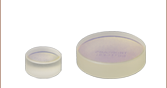
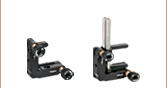
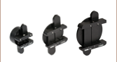
These Ø19 mm mirrors are specifically designed to fit our Polaris Fixed Optic Mounts for laser system design and other OEM applications. This diameter provides a larger clear aperture than Ø1/2" optics while allowing the mounts to maintain a Ø1" footprint.