 Products Home / Motorized Stages / Motorized 30 mm Linear Translation Stages / Kinesis® Precision, Motorized Vertical Translation Stage
Kinesis® Precision, Motorized Vertical Translation Stage
- Vertical Travel Stage with Large Mounting Platform
- Integrated DC Servo Motor and Control Electronics
- Smooth, Repeatable Motion
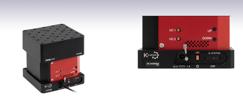
KVS30
Vertical Translation Stage
The unit features intuitive controls, as well as connection options for PC control and external triggering.


Please Wait
| Key Specificationsa | |
|---|---|
| Travel | 30.0 mm (1.18") |
| Load (Max) | 7.0 kg (15.4 lbs) |
| Velocity (Max) | 8.0 mm/s (All Loads) |
| Pitch Deviation | ±25.8 µrad |
| Roll Deviation | ±21.2 µrad |
| Unidirectional Repeatability | ±0.11 µm |
| Bidirectional Repeatability | ±0.12 µm |
| Stability | ±0.06 µm |
| Platform Dimensions | 116.2 mm x 116.2 mm (4.57" x 4.57") |
| Platform Height | 127.5 mm to 157.5 mm (5.02" to 6.20") |

Click to Enlarge
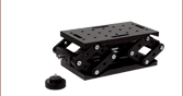
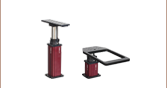
KVS30 Stage Shown in Fully Extended Position
Features
- Motorized Precision Vertical Translation Stage
- ±0.12 µm Bidirectional Repeatability
- 0.1 µm Minimum Incremental Movement
- Control Locally with Up & Down Buttons or Remotely by PC via USB
- External Bidirectional Triggering via I/O Ports (5 V TTL)
- Smooth, DC Servo-Driven Linear Motion
- Full Kinesis® Software Control Suite Included
- Large Mounting Platform with 1/4"-20 and 8-32 (M6 and M4) Taps
- Location-Specific Power Supply Included
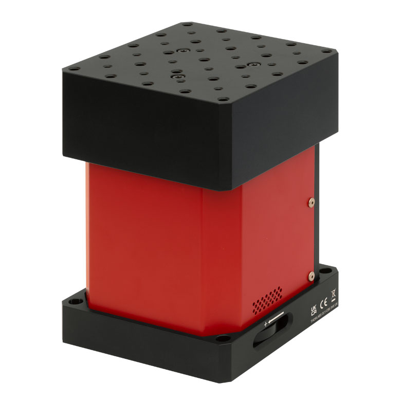
The KVS30(/M) Motorized Vertical Translation Stage is a DC servo-driven linear stage with integrated drive electronics. This stage provides precise, stable height adjustment over the full translation range. The stage motor is capable of moving loads up to 7.0 kg on a large 116.2 mm x 116.2 mm mounting platform with minimal pitch and roll deviation. Crossed-roller bearings and a steel scale linear encoder ensure accurate positioning with high repeatability. See the Specs tab for complete specifications.
The top plate has twenty-five 1/4"-20 (M6) taps and sixteen 8-32 (M4) taps for mounting optomechanical subassemblies. The base of the unit has four through holes that accept 1/4"-20 or M6 screws for mounting to a breadboard or optical table; the holes are spaced such that both imperial and metric breadboards are compatible. The unit is supplied with a region-specific power supply with an input of 100 to 240 VAC. The power connector on the unit includes a locking mechanism to avoid accidental removal of the cord. Note that the power supply unit (PSU) should be connected to the stage before connecting the PSU to a power outlet. A USB cable for controlling the stage via PC is also included.
Local Control
Up and Down buttons on the side of the unit can be used to translate the stage when the motor output is enabled. Alternatively, a manual scroll wheel on the side of the unit can be used to adjust the stage height when closed-loop position control is disabled or the stage is powered off. If the stage is connected to a PC running the Kinesis software while using the manual adjustment wheel, any adjustments will be reflected in the position window of the Kinesis GUI. To enable or disable closed-loop position control, either hold the Up and Down buttons simultaneously until the Status LED flashes or change the setting in the Kinesis software when the unit is connected to a PC.
External Control
A USB port on the side of the stage allows it to be connected to a PC and controlled using our Kinesis® software suite. This software package features new .NET controls that can be used by 3rd party developers working in the latest C#, Visual Basic, LabVIEW, or any .NET compatible languages to create custom applications. Parameter settings can be adjusted on the PC and stored in non-volatile memory within the unit itself. When the unit is next powered up, these settings are applied automatically. Please see the Kinesis Software and Kinesis Tutorials tabs for more details. External bidirectional triggering is possible using the two I/O ports on the unit.
| Specificationsa | |
|---|---|
| Travel | 30.0 mm (1.18") |
| Unidirectional Repeatability | ±0.11 µm |
| Bidirectional Repeatability | ±0.12 µm |
| Accuracy | 0.9 µm |
| Homing Repeatability | ±0.36 µm |
| Pitch Deviationb | ±25.8 µrad |
| Compliance in Pitchb | 39.0 µrad/N·m |
| Maximum Torque (Pitch)c | 5.0 N·m |
| Roll Deviation | ±21.2 µrad |
| Compliance in Rollb | 19.0 µrad/N·m |
| Maximum Torque (Roll)c | 9.0 N·m |
| Maximum Load | 7.0 kg (15.4 lbs) |
| Maximum Velocity | 8.0 mm/s (All Loads) |
| Maximum Acceleration | 5.0 mm/s2 (All Loads) |
| Minimum Incremental Motiond | 0.1 µm |
| Stability | ±0.06 µm |
| Lead Screw Pitch | 1.0 mm |
| Operating Temperature | 5 to 40 °C |
| Dimensions (W x D x H) at Homed Position |
116.2 mm x 116.2 mm x 127.5 mm (4.57" x 4.57" x 5.02") |
| Weight | 3.4 kg (7.48 lbs) |
| Input Power Requirements | |
| Current | 1 A (Max) |
| Nominal Voltage | 15 VDC |
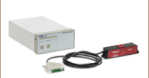
Computer Connection
*The USB 3.0 port is compatible with a USB 2.0 Micro B connector if the Micro B connector is plugged into the shaded region in the photo above. A USB 3.0 type A to type Micro B cable is included with each KVS30(/M) stage.
I/O 1MMCX Female |
I/O 2MMCX Female |
 |
|
| +5 V TTL | +5 V TTL |
| These connectors can be independently configured for use with external trigger input or output signal (5 V TTL levels). | |
| In input mode, logic levels are TTL compatible: <0.8 V is recognized as Low and >2.4 V is recognized as High. The default state when the port is unconnected is High. | |
| In output mode, the port provides a push-pull drive of 5 V with a maximum current of 8 mA. | |
Power Supply

3.15 mm Jack Connector
Thorlabs' Kinesis® software can be used to control devices in the Kinesis or APT™ family, which covers a wide range of motion controllers ranging from small, low-powered, single-channel drivers (such as the K-Cubes and T-Cubes) to high-power, multi-channel, modular 19" rack nanopositioning systems (the APT Rack System).
The Kinesis Software features new .NET controls which can be used by 3rd party developers working in the latest C#, Visual Basic, LabVIEW™ or any .NET compatible languages to create custom applications. Low level DLL libraries are included for applications not expected to use the .NET framework. A Central Sequence Manager supports integration and synchronization of all Thorlabs motion control hardware.
By providing these common software platforms, Thorlabs has ensured that users can easily mix and match any of the APT and Kinesis controllers in a single application, while only having to learn a single set of software tools. In this way, it is perfectly feasible to combine any of the controllers from the low-powered, single-axis to the high-powered, multi-axis systems and control all from a single, PC-based unified software interface.
The software packages allow two methods of usage: graphical user interface (GUI) utilities for direct interaction with and control of the controllers 'out of the box', and a set of programming interfaces that allow custom-integrated positioning and alignment solutions to be easily programmed in the development language of choice.
Software
Kinesis Version 1.14.47
The Kinesis Software Package, which includes a GUI for control of Thorlabs' Kinesis and APT™ system controllers.
Also Available:
- Communications Protocol

Kinesis GUI Screen
Thorlabs' Kinesis® software features new .NET controls which can be used by third-party developers working in the latest C#, Visual Basic, LabVIEW™, or any .NET compatible languages to create custom applications.
C#
This programming language is designed to allow multiple programming paradigms, or languages, to be used, thus allowing for complex problems to be solved in an easy or efficient manner. It encompasses typing, imperative, declarative, functional, generic, object-oriented, and component-oriented programming. By providing functionality with this common software platform, Thorlabs has ensured that users can easily mix and match any of the Kinesis controllers in a single application, while only having to learn a single set of software tools. In this way, it is perfectly feasible to combine any of the controllers from the low-powered, single-axis to the high-powered, multi-axis systems and control all from a single, PC-based unified software interface.
The Kinesis System Software allows two methods of usage: graphical user interface (GUI) utilities for direct interaction and control of the controllers 'out of the box', and a set of programming interfaces that allow custom-integrated positioning and alignment solutions to be easily programmed in the development language of choice.
For a collection of example projects that can be compiled and run to demonstrate the different ways in which developers can build on the Kinesis motion control libraries, click on the links below. Please note that a separate integrated development environment (IDE) (e.g., Microsoft Visual Studio) will be required to execute the Quick Start examples. The C# example projects can be executed using the included .NET controls in the Kinesis software package (see the Kinesis Software tab for details).
 |
Click Here for the Kinesis with C# Quick Start Guide Click Here for C# Example Projects Click Here for Quick Start Device Control Examples |
|
LabVIEW
LabVIEW can be used to communicate with any Kinesis- or APT-based controller via .NET controls. In LabVIEW, you build a user interface, known as a front panel, with a set of tools and objects and then add code using graphical representations of functions to control the front panel objects. The LabVIEW tutorial, provided below, provides some information on using the .NET controls to create control GUIs for Kinesis- and APT-driven devices within LabVIEW. It includes an overview with basic information about using controllers in LabVIEW and explains the setup procedure that needs to be completed before using a LabVIEW GUI to operate a device.
 |
Click Here to View the LabVIEW Guide Click Here to View the Kinesis with LabVIEW Overview Page |
|
| Posted Comments: | |
Dovlet Seyit
(posted 2024-04-04 08:58:23.103) Hello,
Why this product has way better repeatibliity (0.12microns) than M30XY/M? I thought they have same technology spolineni
(posted 2024-04-10 05:31:47.0) Thank you for your inquiry. The better repeatability of the KVS30 is a result of its unique design and construction, which includes features such as crossed-roller bearings and a high-resolution linear encoder. I will personally contact you to offer more detailed information on this topic. Ludo
(posted 2021-03-11 06:27:52.253) I'll (partially) answer my own question: "can this stage be used with Linux?" It seems that yes (see Charles' answer to feedback from "user" below), but the Kinesis software provided by Thorlabs is only Gate$' Micro$oft compatible. Using this stage with Linux requires the end user to first understand the APT communication protocol (nice from Thorlabs to provide this documentation) and write the code to implement the protocol, adjust PID parameters and perform tests. This prompts a new question: the APT protocol documentation doesn't list the KVS30, which is the equivalent controller one should refer to? cwright
(posted 2021-03-12 11:03:59.0) Response from Charles at Thorlabs: Hello Ludo and thank you for your feedback. I will forward this on and ensure that the command protocol is updated. I will also contact you directly to give you a list of commands which can be used. This is a DC servo driven stage so the commands will typically align with those of the TDC/KDC. Mikkel Bregnhøj
(posted 2020-10-03 03:21:54.373) Dear Thorlabs
Your KVS30/M Z-stage looks to be the perfect platform for reflection SFG measurements, and other multi-beam nonlinear optic techniques where dynamic control of the sample height is essential.
However, the minimal platform height of 12.5 cm is a little too heigh for the physical space on our tightly packed optical table.
Could you consider designing a version that is somewhat lower, but with approx. the same dynamic travel range and specs? One can always raise the platform, but lowering it is impossible.
Kind regards
Mikkel Bregnhøj DJayasuriya
(posted 2020-10-06 08:34:33.0) Hello Mikkel, Thank you for getting in touch with us. Reducing the platform height with the current design would be a bit tricky due to the motor and bearing limits. I will get in touch with you directly top discus your application. user
(posted 2020-02-29 12:53:25.613) Too bad these motorized instruments are not OS agnostic, which means I cannot put it into a system where OS is dictated by DUT. Make your products like the FW102C, built-in FTDI RS232 controller, so I can send text commands from any OS to operate the equipment. cwright
(posted 2020-03-03 06:01:47.0) Response from Charles at Thorlabs: Thank you for your feedback. While this device does not have a dedicated port for such communication, you can control this device with text commands via the RS232 standard.
There are FTDI drivers which allow for interfacing with a virtual COM port, which allows for OS agnostic operation through our communication protocal document. You can view this communications protocol here:
https://www.thorlabs.com/software_pages/ViewSoftwarePage.cfm?Code=Motion_Control |
Motorized Linear Translation Stages
Thorlabs' motorized linear translation stages are offered in a range of maximum travel distances, from a stage with 20 µm of piezo translation to our 600 mm direct drive stage. Many of these stages can be assembled in multi-axis configurations, providing XY or XYZ translation. For fiber coupling applications, please see our multi-axis stages, which offer finer adjustment than our standard motorized translation stages. In addition to motorized linear translation stages, we offer motorized rotation stages and goniometers. We also offer manual translation stages.
Piezo Stages
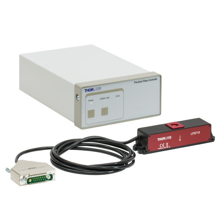
These stages incorporate piezoelectric elements in a variety of drive mechanisms. ORIC® stages incorporate piezo inertia drives that use "stick-slip" friction properties to obtain extended travel ranges. Our Nanoflex™ translation stages use standard piezo chips along with manual actuators. Elliptec® stages use resonant piezo motors to push and pull the moving platform through resonant elliptical motion. Our LPS710E z-axis stage features a mechanically amplified piezo design and includes a matched controller.
| Piezoelectric Stages | ||||
|---|---|---|---|---|
| Product Family | ORIC® PDXZ1 Closed-Loop 4.5 mm Vertical Stage |
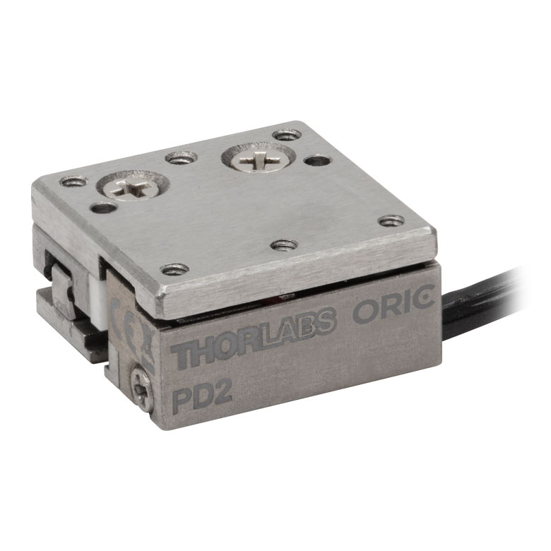
ORIC® PD2 Open-Loop 5 mm Stage |
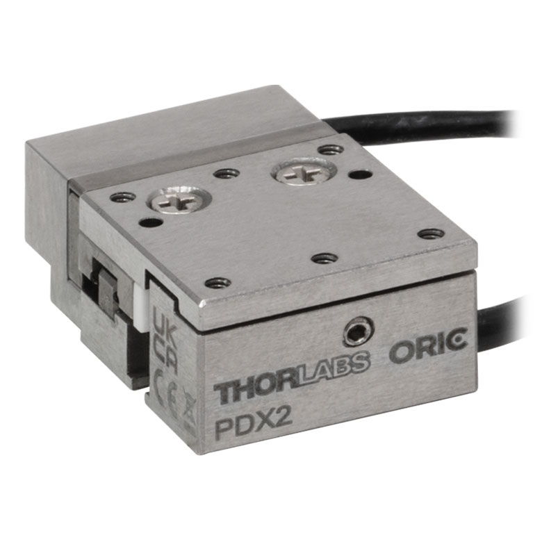
ORIC® PDX2 Closed-Loop 5 mm Stage |
|
| Click Photo to Enlarge |
 |
 |
 |
|
| Travel | 4.5 mm | 5 mm | ||
| Speed | 1 mm/s (Typ.)a | 10 mm/s (Typ. Max)b | 8 mm/s (Typ.)c | |
| Drive Type | Piezoelectric Inertia Drive | |||
| Possible Axis Configurations | Z | X, XY, XYZ | ||
| Mounting Surface Size |
45.0 mm x 42.0 mm | 13 mm x 13 mm | ||
| Additional Details | ||||
| Piezoelectric Stages | |||||
|---|---|---|---|---|---|
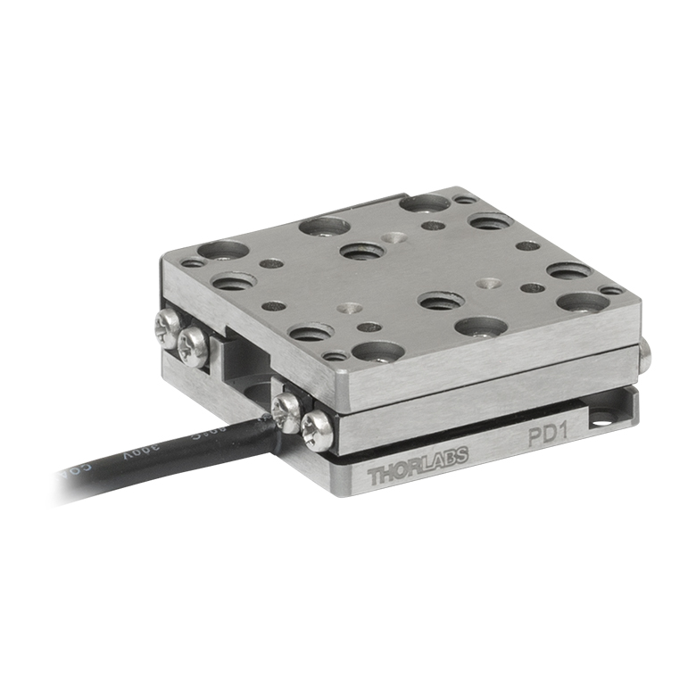
| Product Family | ORIC® PD1 Open-Loop 20 mm Stage |
ORIC® PD1D Open-Loop 20 mm Monolithic XY Stage |
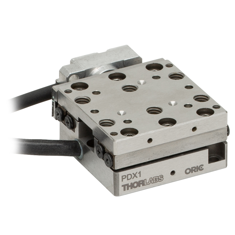
ORIC® PDX1 Closed-Loop 20 mm Stage |
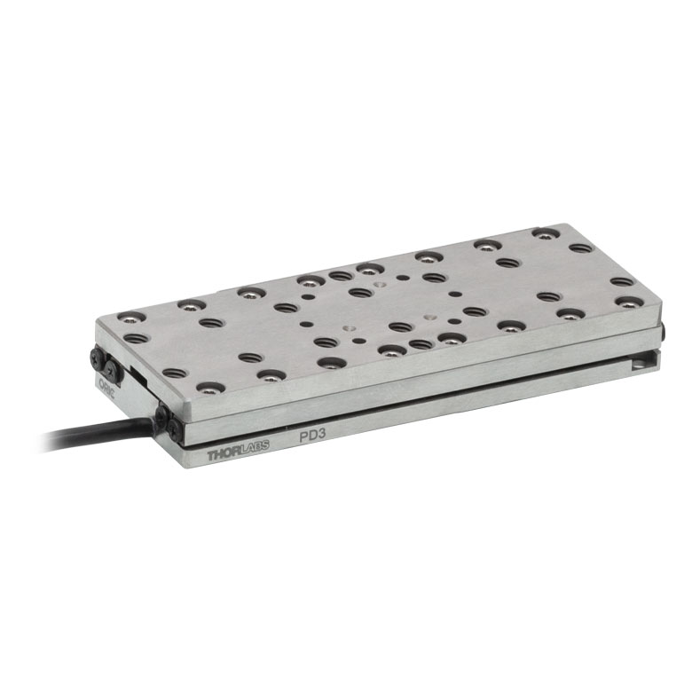
ORIC® PD3 Open-Loop 50 mm Stage |
|
| Click Photo to Enlarge |
 |
 |
 |
 |
|
| Travel | 20 mm | 50 mm | |||
| Speed | 3 mm/s (Typ. Max)a | 20 mm/s (Typ. Max)b | 10 mm/sc | ||
| Drive Type | Piezoelectric Inertia Drive | ||||
| Possible Axis Configurations | X, XY, XYZ | XY, XYZ | X, XY, XYZ | X, XY, XYZ | |
| Mounting Surface Size |
30 mm x 30 mm | 80 mm x 30 mm | |||
| Additional Details | |||||
| Piezoelectric Stages | ||||||
|---|---|---|---|---|---|---|
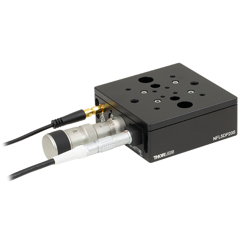
| Product Family | Nanoflex™ 20 µm Stage with 5 mm Actuator |
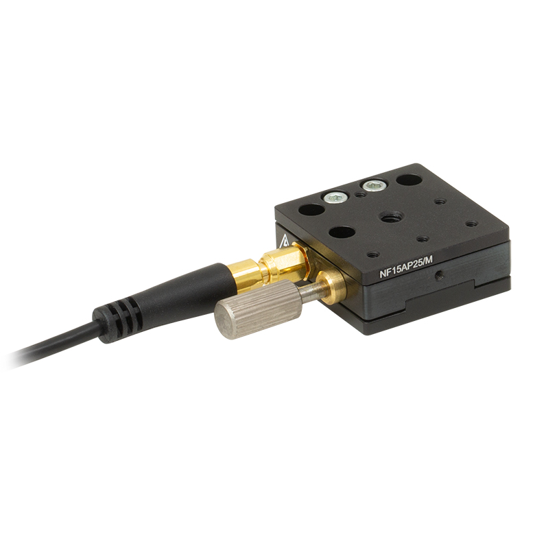
Nanoflex™ 25 µm Stage with 1.5 mm Actuator |
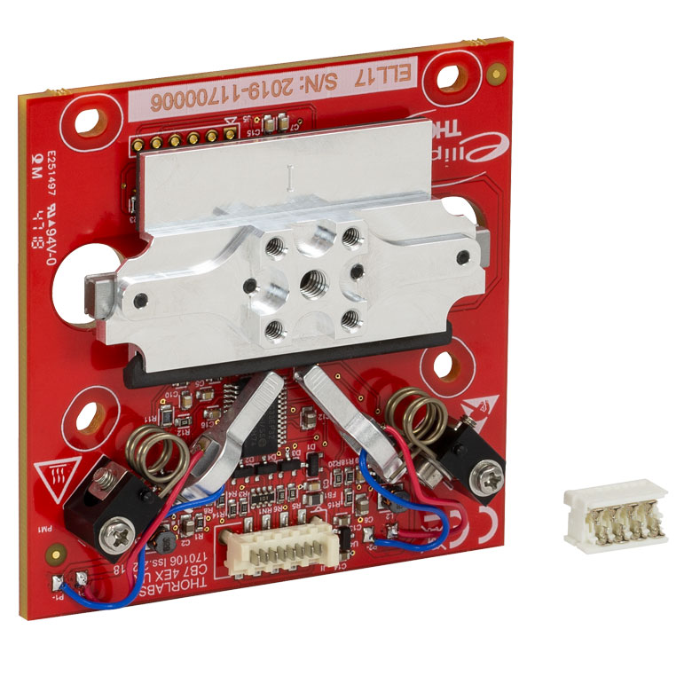
Elliptec® 28 mm Stage | Elliptec® 60 mm Stage | LPS710E 1.1 mm Vertical Stage | |
| Click Photo to Enlarge |
 |
 |
 |
 |
 |
|
| Travel | 20 µm + 5 mm Manual | 25 µm + 1.5 mm Manual | 28 mm | 60.0 mm | 1.1 mm | |
| Maximum Velocity | - | 180 mm/s | 90 mm/s | - | ||
| Drive Type | Piezo with Manual Actuator | Resonant Piezoelectric Motor | Amplified Piezo | |||
| Possible Axis Configurations | X, XY, XYZ | X | Z | |||
| Mounting Surface Size | 75 mm x 75 mm | 30 mm x 30 mm | 15 mm x 15 mm | 21 mm x 21 mm | ||
| Additional Details | ||||||
Stepper Motor Stages
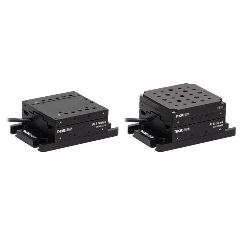
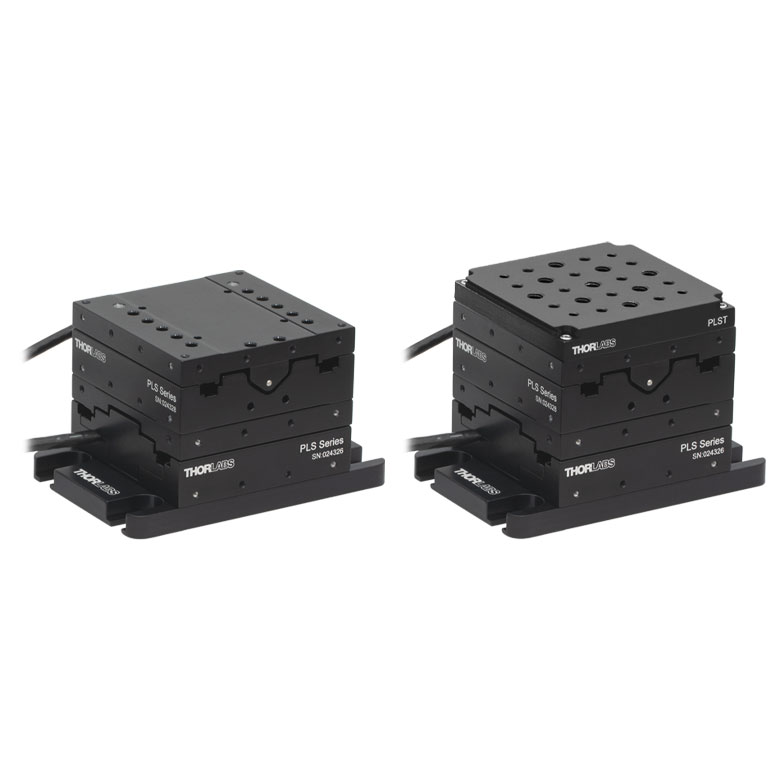
These translation stages feature removable or integrated stepper motors and long travel ranges up to 300 mm. Many of these stages either have integrated multi-axis capability (PLSXY) or can be assembled into multi-axis configurations (PLSX, LNR Series, NRT Series, and LTS Series stages). The MLJ150 stage also offers high load capacity vertical translation.
| Stepper Motor Stages | |||||
|---|---|---|---|---|---|
| Product Family | PLSX with and without PLST(/M) Top Plate 1" Stage |
PLSXY with and without PLST(/M) Top Plate 1" Stage |
LNR Series 25 mm Stage |
LNR Series 50 mm Stage |
|
| Click Photo to Enlarge |
 |
 |
 |
 |
|
| Travel | 1" | 25 mm | 50 mm | ||
| Maximum Velocity | 7.0 mm/s | 2.0 mm/s | 50 mm/s | ||
| Possible Axis Configurations |
X, XY | X, XY, XYZ | X, XY, XYZ | ||
| Mounting Surface Size |
3" x 3" | 60 mm x 60 mm | 100 mm x 100 mm | ||
| Additional Details | |||||
| Stepper Motor Stages | ||||||
|---|---|---|---|---|---|---|
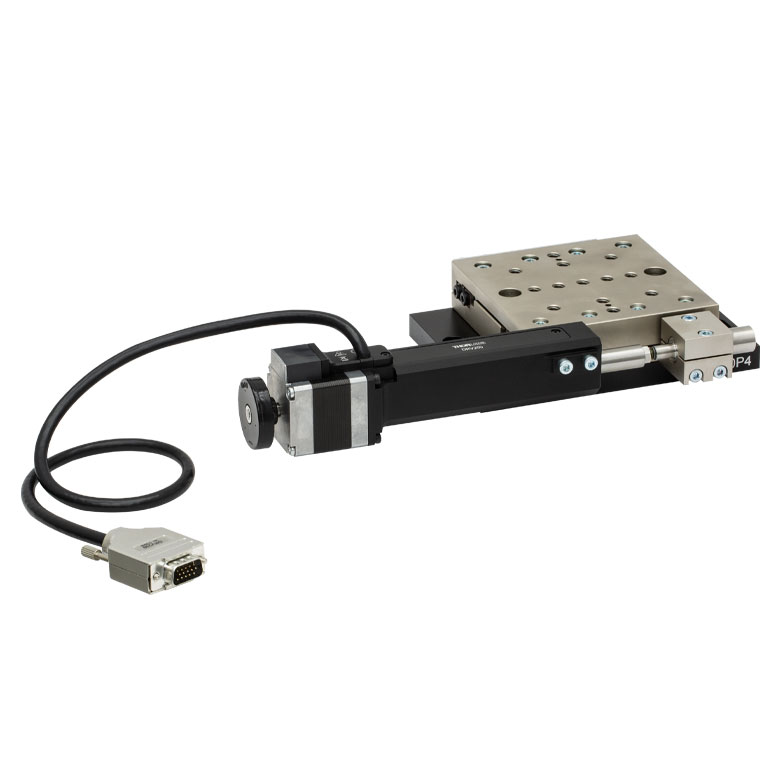
| Product Family | NRT Series 100 mm Stage |
NRT Series 150 mm Stage |
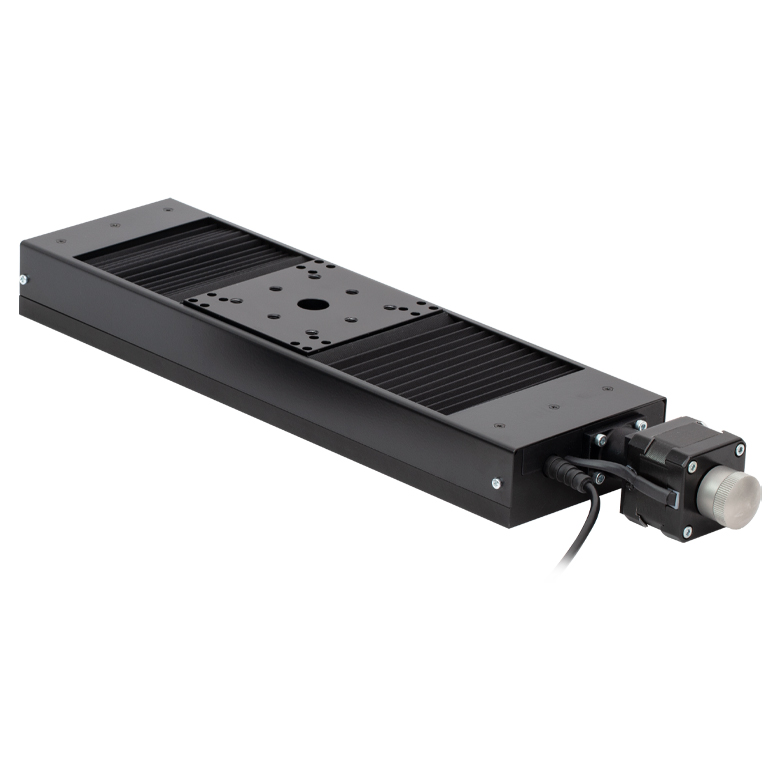
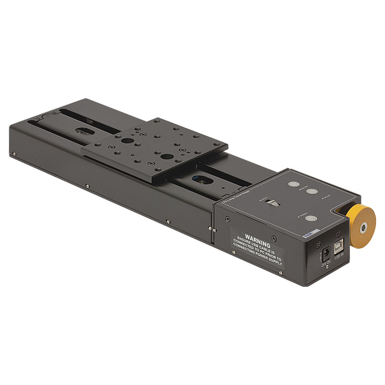
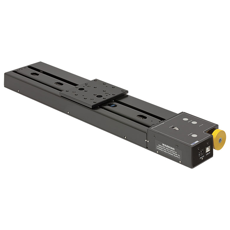
LTS Series 150 mm Stage |
LTS Series 300 mm Stage |
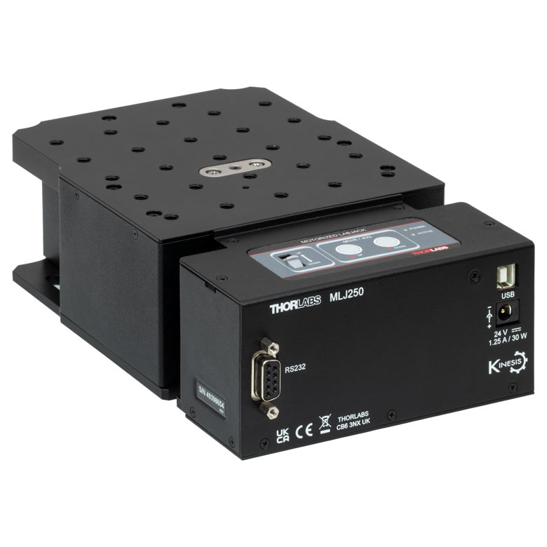
MLJ250 50 mm Vertical Stage |
|
| Click Photo to Enlarge |
 |
 |
 |
 |
 |
|
| Travel | 100 mm | 150 mm | 150 mm | 300 mm | 50 mm | |
| Maximum Velocity | 30 mm/s | 50 mm/s | 3.0 mm/s | |||
| Possible Axis Configurations |
X, XY, XYZ | X, XY, XYZ | Z | |||
| Mounting Surface Size |
84 mm x 84 mm | 100 mm x 90 mm | 148 mm x 131 mm | |||
| Additional Details | ||||||
DC Servo Motor Stages
Thorlabs offers linear translation stages with removable or integrated DC servo motors. These stages feature low profiles and many can be assembled in multi-axis configurations.
| DC Servo Motor Stages | ||||
|---|---|---|---|---|
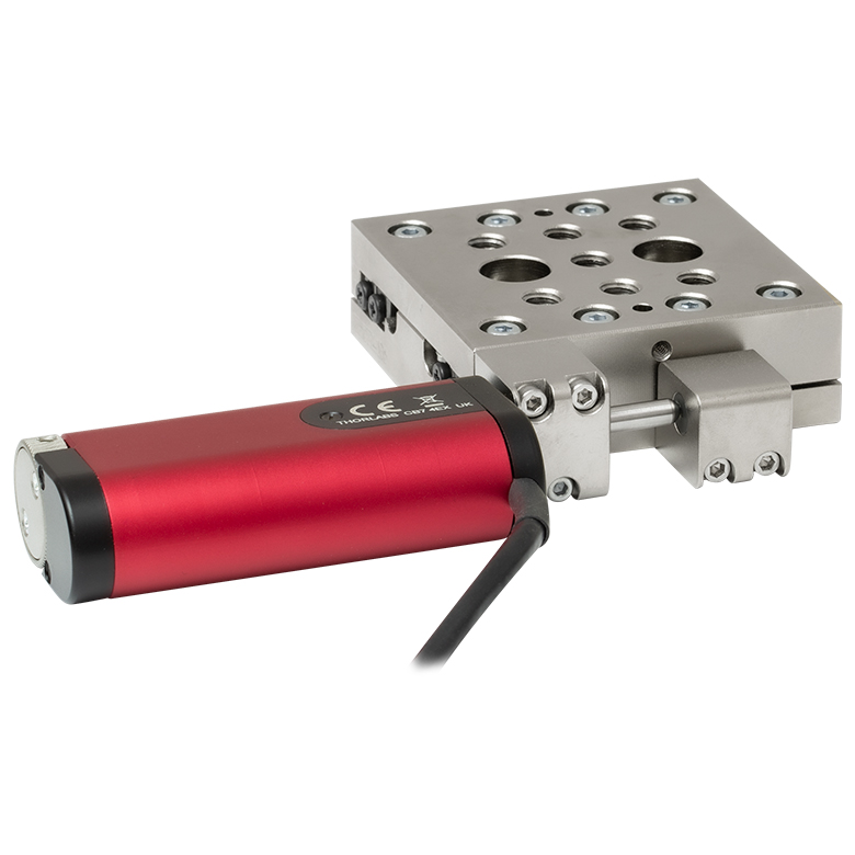
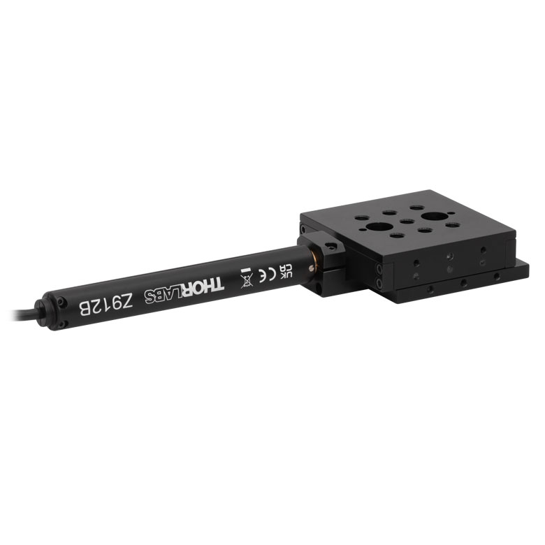
| Product Family | MT Series 12 mm Stages |
PT Series 25 mm Stages |
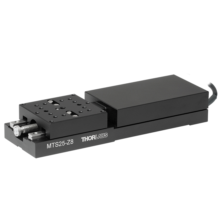
MTS Series 25 mm Stage |
MTS Series 50 mm Stage |
| Click Photo to Enlarge |
 |
 |
 |
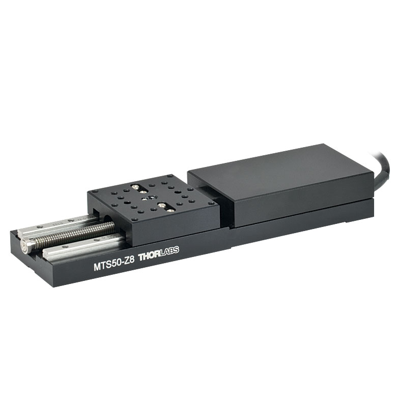 |
| Travel | 12 mm | 25 mm | 25 mm | 50 mm |
| Maximum Velocity | 2.6 mm/s | 2.4 mm/s | ||
| Possible Axis Configurations | X, XY, XYZ | X, XY, XYZ | ||
| Mounting Surface Size |
61 mm x 61 mm | 101.6 mm x 76.2 mm | 43 mm x 43 mm | |
| Additional Details | ||||
| DC Servo Motor Stages | ||||
|---|---|---|---|---|
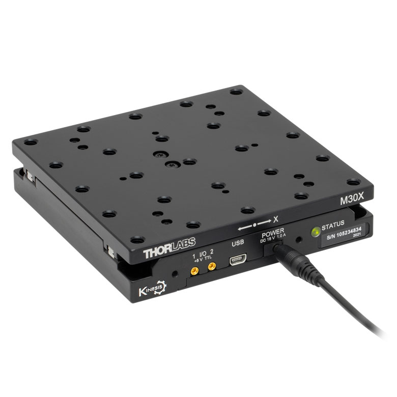
| Product Family | M30 Series 30 mm Stage |
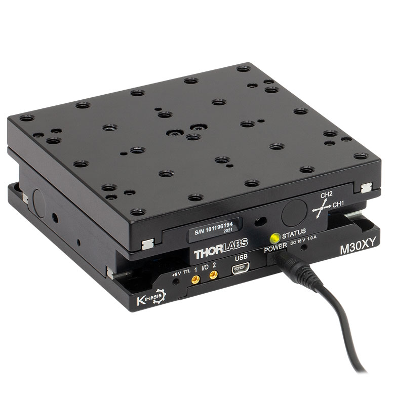
M30 Series 30 mm Monolithic XY Stage |
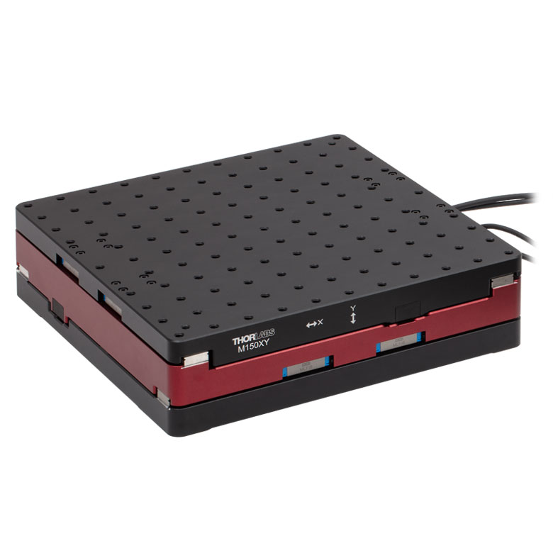
M150 Series 150 mm XY Stage |
KVS30 30 mm Vertical Stage |
| Click Photo to Enlarge |
 |
 |
 |
 |
| Travel | 30 mm | 150 mm | 30 mm | |
| Maximum Velocity | 2.4 mm/s | X-Axis: 170 mm/s Y-Axis: 230 mm/s |
8.0 mm/s | |
| Possible Axis Configurations | X, Z | XY, XZ | XY | Z |
| Mounting Surface Size |
115 mm x 115 mm | 272.4 mm x 272.4 mm | 116.2 mm x 116.2 mm | |
| Additional Details | ||||
Direct Drive Stages
These low-profile stages feature integrated brushless DC servo motors for high speed translation with zero backlash. When no power is applied, the platforms of these stages have very little inertia and are virtually free running. Hence these stages may not be suitable for applications where the stage's platform needs to remain in a set position when the power is off. We do not recommend mounting these stages vertically.
| Direct Drive Stages | |||||
|---|---|---|---|---|---|
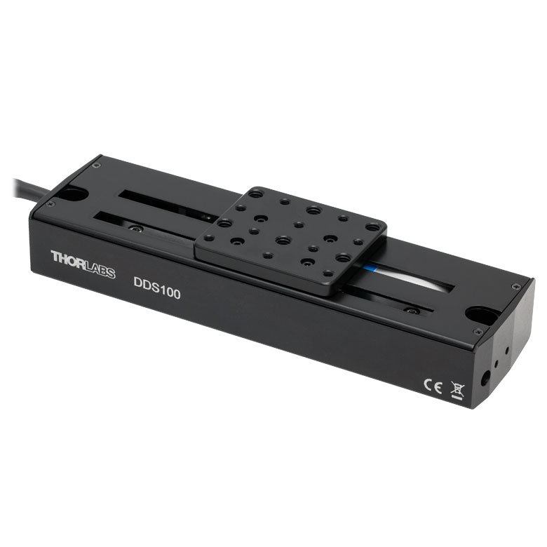
| Product Family | DDS Series 50 mm Stage |
DDS Series 100 mm Stage |
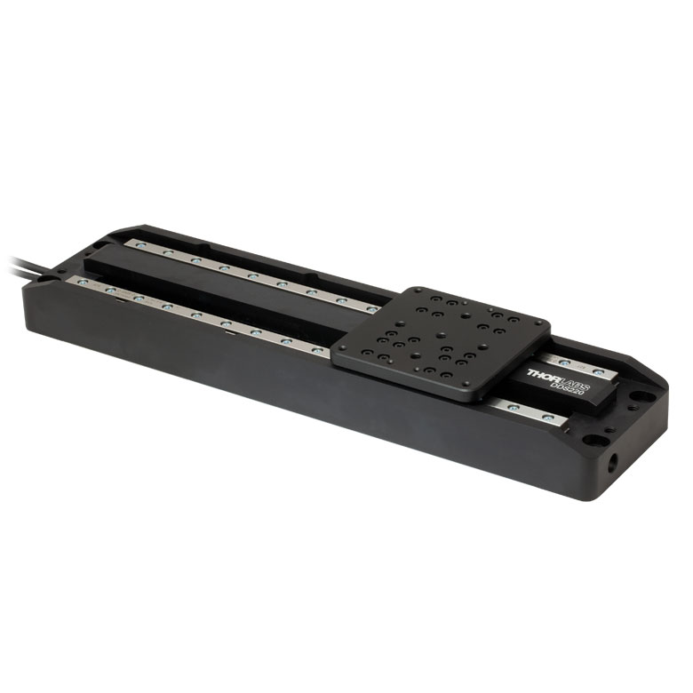
DDS Series 220 mm Stage |
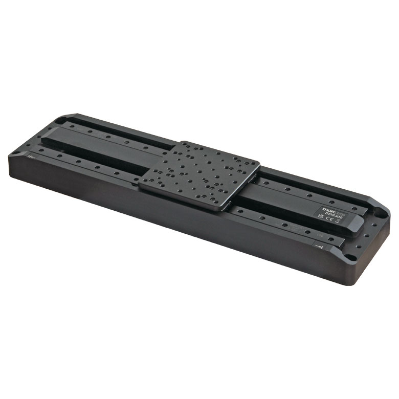
DDS Series 300 mm Stage |
DDS Series 600 mm Stage |
| Click Photo to Enlarge |
 |
 |
 |
 |
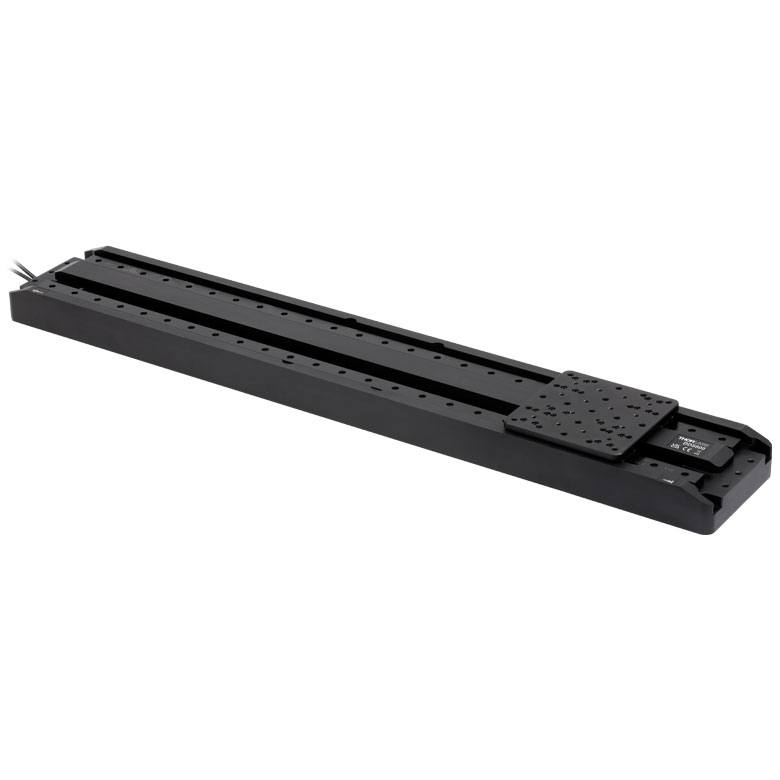 |
| Travel | 50 mm | 100 mm | 220 mm | 300 mm | 600 mm |
| Maximum Velocity | 500 mm/s | 300 mm/s | 400 mm/s | 400 mm/s | |
| Possible Axis Configurations | X, XY | X, XY | X | X | |
| Mounting Surface Size | 60 mm x 52 mm | 88 mm x 88 mm | 120 mm x 120 mm | ||
| Additional Details | |||||

 Zoom
Zoom
Click for Details
KVS30 Mechanical Drawing. Values for the metric version are given in parentheses.
- 30.0 mm Vertical Translation
- 127.5 mm Minimum Platform Height
- ±0.12 µm Bidirectional Repeatability
- 0.1 µm Minimum Incremental Movement
- Control Locally with Up & Down Buttons or Remotely by PC via USB
- External Bidirectional Triggering via I/O Ports (5 V TTL)
This vertical translation stage provides precise, stable height adjustment with smooth, repeatable motion. The large 116.2 mm x 116.2 mm platform is capable of moving loads up to 7.0 kg at speeds up to 8.0 mm/s. When the stage is fully lowered, the platform height is 127.5 mm.
The unit features Up and Down buttons for controlling the stage. When closed-loop control is disabled or when the stage is powered off, a manual scroll wheel can be used for adjustment. The USB connector allows PC control using our Kinesis® software control suite.
Two I/O ports enable external bidirectional triggering (5 V TTL). Mating cables for these ports are available separately below. A power supply with a region-specific adapter plug is included with the stage.

 Zoom
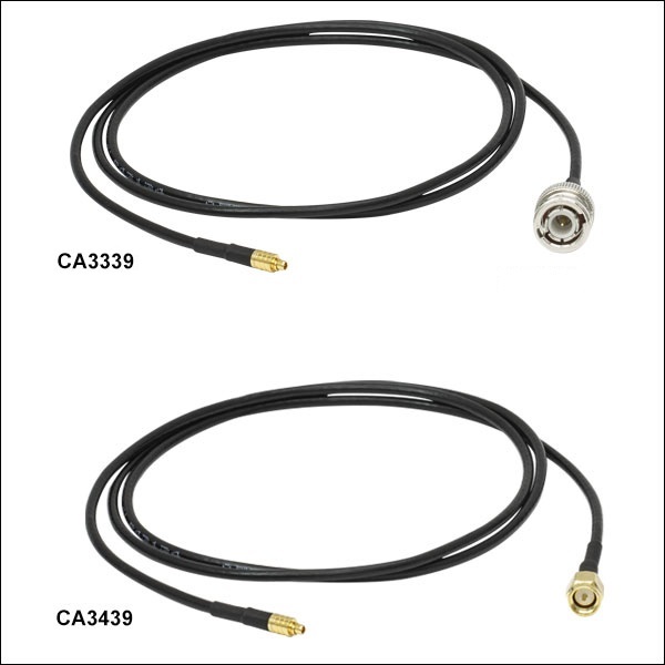
Zoom- Cables for Trigger Ports on KVS30(/M) Translation Stage
- MMCX Male Connector to BNC or SMA Male Connector
- DC - 6 GHz Frequency Range
- 50 Ω Normal Impedance
- 170 V Max Operating Voltage
These cables enable external triggering via the I/O ports on the KVS30(/M) stage. The CA3339 (1 m long) and CA3272 (1.8 m long) cables each feature a male BNC termination while the CA3439 cable (1 m long) has a male SMA termination.