 Products Home / Fiber Components / Collimation / Coupling / Air-Spaced Doublet Collimators: FC/APC, FC/PC, & SMA
Air-Spaced Doublet Collimators: FC/APC, FC/PC, & SMA
- Multi-Element Lens Design for Diffraction-Limited Performance
- Options for FC/APC, FC/PC, or SMA Connectors
- Collimated Beam Diameters Range from 5.3 to 8.0 mm
- Simplifies Fiber-Coupled Detection Systems
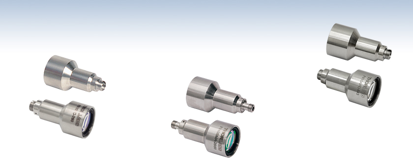
F810FC-780
780 nm, Focal Length: 36.01 mm
F810SMA-2000
2.0 µm, Focal Length: 37.52 mm
Back
F810APC-543
543 nm, Focal Length: 34.74 mm
Front
Back
Front
Back
Front


Please Wait
Features
- Fiber Collimators with FC/APC (2.2 mm Wide Key), FC/PC (2.2 mm Wide Key), or SMA Connectors
- Factory-Aligned Collimation Package for Wavelengths from 405 nm to 2 µm
- Simplifies Free-Space Laser to Fiber Coupling
- Multi-Element Lens Design for Diffraction-Limited Performance
- UV Fused Silica or N-SF6 Lenses
- Non-Magnetic Stainless Steel Housing
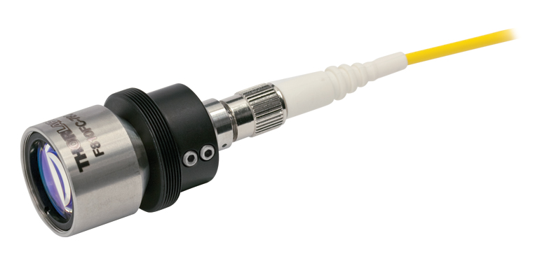
The F810 Series Fiber Collimation Packages are pre-aligned to collimate a laser beam propagating from the tip of an FC/APC, FC/PC, or SMA terminated fiber with diffraction-limited performance at the design wavelength. Since the F810 Series fiber collimators do not have any movable parts, they are compact and not susceptible to misalignment. Due to chromatic aberration, the effective focal length (EFL) of the doublet lens is wavelength dependent. As a result, these collimators will only perform optimally at the design wavelength. The doublet lens, which features an antireflection (AR) coating that minimizes surface reflections, is factory aligned for each design wavelength so that the lens is one focal length away from a fiber tip inserted into the collimator. Additionally, the receptacles for the FC/APC versions are angled so that light exiting the fiber enters the collimator perpendicular to the focal plane.
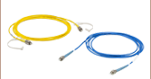
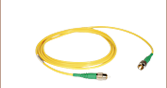
We recommend using the F810APC and F810FC collimation packages with our AR-coated single mode fiber optic patch cables. These cables feature an antireflective coating on one fiber end for increased transmission and improved return loss at the fiber-to-free-space interface. F810SMA fiber collimation packages are optimized for single mode fibers and are compatible with our SMA-terminated hybrid single mode fiber optic patch cables. Alternatively, our large selection of fiber patch cables include uncoated options that can also be used.
If our stock collimators are not suitable for your application, please contact Tech Sales; we can align collimation packages at custom wavelengths. We also offer a line of adjustable collimation packages called FiberPorts that are well suited for a wide range of wavelengths and are ideal solutions for adjustable, compact fiber couplers. For other fiber collimation and coupling options, see our Collimation and Coupling guide.
Theoretical Approximation of the Divergence
The divergence angle listed in the specifications tables below is the theoretical full-angle divergence when using the fiber collimator at its design wavelength with the listed fiber. Simulations of the theoretical divergence of the F810 collimators at wavelengths other than the design wavelengths are shown below. Similarly, the beam diameter as a function of propogration distance was simulated for each of our F810 collimators at the design wavelength, assuming input from the design fiber and a Gaussian intensity profile.
The graphs below show the reflectance with respect to wavelength of the AR coatings used on the lens surfaces in our F810 series collimators. The blue shaded region indicates the wavelength range specified for each coating. The table below details the AR coating designations with their corresponding wavelength ranges and average reflectance.
| AR Coating Information | ||||||
|---|---|---|---|---|---|---|
| Coating Designation | A | 405 | B | 1064 | C | D |
| Coating Range | 350 - 700 nm | 450 nm | 650 - 1050 nm | 1054 - 1074 nm | 1050 - 1620 nm | 1.8 - 2.4 μm |
| Reflectance | Ravg < 0.5% | Rabs < 0.25% | Ravg < 0.5% | Ravg < 0.25% | Ravg < 0.5% | Ravg < 0.5% |

Click to Enlarge
Click Here for Data
Click to Enlarge
Click Here for Data
 Click to Enlarge
Click Here for Data
 Click to Enlarge
Click Here for Data
 Click to Enlarge
Click Here for Data
Click to Enlarge
Click Here for Data
Theoretical Approximation of the Divergence Angle
The full-angle beam divergence listed in the specifications tables is the theoretically-calculated value associated with the fiber collimator. This divergence angle is easy to approximate theoretically using the formula below as long as the light emerging from the fiber has a Gaussian intensity profile. Consequently, the formula works well for single mode fibers, but it will underestimate the divergence angle for multimode (MM) fibers since the light emerging from a multimode fiber has a non-Gaussian intensity profile.
The Full Divergence Angle (in degrees) is given by
where MFD is the mode field diameter and f is the focal length of the collimator. (Note: MFD and f must have the same units in this equation).
Example:
When the F220FC-A collimator (f ≈ 11.0 mm; not exact since the design wavelength is 543 nm) is used to collimate 515 nm light emerging from a 460HP fiber (MFD = 3.5 µm), the divergence angle is approximately given by
θ ≈ (0.0035 mm / 11.0 mm) x (180 / pi) = 0.018°.
When the beam divergence angle was measured for the F220FC-A collimator, a 460HP fiber was used with 543 nm light. The result was a divergence angle of 0.018°.
Theoretical Approximation of the Output Beam Diameter
The output beam diameter can be approximated from
where λ is the wavelength of light being used, MFD is the mode field diameter, and f is the focal length of the collimator. (Note: MFD and f must have the same units in this equation).
Example:
When the F240FC-1550 collimator (f = 8.18 mm) is used with the P1-SMF28E-FC-1 patch cable (MFD = 10.4 µm) and 1550 nm light, the output beam diameter is
d ≈ (4)(0.00155 mm)[8.18 mm / (pi · 0.0104 mm)] = 1.55 mm.
Theoretical Approximation of the Maximum Waist Distance
The maximum waist distance, which is the furthest distance from the lens the waist can be located in order to maintain collimation, may be approximated by
where f is the focal length of the collimator, λ is the wavelength of light used, and MFD is the mode field diameter. (Note: MFD and f must have the same units in this equation).
Example:
When the F220FC-532 collimator (f = 10.9 mm) is used with the P1-460B-FC-1 patch cable (MFD ≈ 4.0 µm; calculated approximate value) and 532 nm light, then the maximum waist distance is approximately
zmax ≈ 10.9 mm + [2 · (10.9 mm)2 · 0.000532 mm] / [pi · (0.004 mm)2] = 2526 mm.
| Damage Threshold Specifications | |
|---|---|
| Item # Suffix | Damage Threshold |
| -543 | 7.5 J/cm2 (532 nm, 10 ns, 10 Hz, Ø0.362 mm) |
| -1064 | 7.5 J/cm2 (1064 nm, 10 ns, 10 Hz, Ø0.442 mm) |
Damage Threshold Data for Thorlabs' Air-Spaced Doublet Collimators
The specifications to the right are measured data for a selection of Thorlabs' air-spaced doublet collimators. Damage threshold specifications are constant for these collimators, regardless of the connector type.
Laser Induced Damage Threshold Tutorial
The following is a general overview of how laser induced damage thresholds are measured and how the values may be utilized in determining the appropriateness of an optic for a given application. When choosing optics, it is important to understand the Laser Induced Damage Threshold (LIDT) of the optics being used. The LIDT for an optic greatly depends on the type of laser you are using. Continuous wave (CW) lasers typically cause damage from thermal effects (absorption either in the coating or in the substrate). Pulsed lasers, on the other hand, often strip electrons from the lattice structure of an optic before causing thermal damage. Note that the guideline presented here assumes room temperature operation and optics in new condition (i.e., within scratch-dig spec, surface free of contamination, etc.). Because dust or other particles on the surface of an optic can cause damage at lower thresholds, we recommend keeping surfaces clean and free of debris. For more information on cleaning optics, please see our Optics Cleaning tutorial.
Testing Method
Thorlabs' LIDT testing is done in compliance with ISO/DIS 11254 and ISO 21254 specifications.
First, a low-power/energy beam is directed to the optic under test. The optic is exposed in 10 locations to this laser beam for 30 seconds (CW) or for a number of pulses (pulse repetition frequency specified). After exposure, the optic is examined by a microscope (~100X magnification) for any visible damage. The number of locations that are damaged at a particular power/energy level is recorded. Next, the power/energy is either increased or decreased and the optic is exposed at 10 new locations. This process is repeated until damage is observed. The damage threshold is then assigned to be the highest power/energy that the optic can withstand without causing damage. A histogram such as that below represents the testing of one BB1-E02 mirror.

The photograph above is a protected aluminum-coated mirror after LIDT testing. In this particular test, it handled 0.43 J/cm2 (1064 nm, 10 ns pulse, 10 Hz, Ø1.000 mm) before damage.

| Example Test Data | |||
|---|---|---|---|
| Fluence | # of Tested Locations | Locations with Damage | Locations Without Damage |
| 1.50 J/cm2 | 10 | 0 | 10 |
| 1.75 J/cm2 | 10 | 0 | 10 |
| 2.00 J/cm2 | 10 | 0 | 10 |
| 2.25 J/cm2 | 10 | 1 | 9 |
| 3.00 J/cm2 | 10 | 1 | 9 |
| 5.00 J/cm2 | 10 | 9 | 1 |
According to the test, the damage threshold of the mirror was 2.00 J/cm2 (532 nm, 10 ns pulse, 10 Hz, Ø0.803 mm). Please keep in mind that these tests are performed on clean optics, as dirt and contamination can significantly lower the damage threshold of a component. While the test results are only representative of one coating run, Thorlabs specifies damage threshold values that account for coating variances.
Continuous Wave and Long-Pulse Lasers
When an optic is damaged by a continuous wave (CW) laser, it is usually due to the melting of the surface as a result of absorbing the laser's energy or damage to the optical coating (antireflection) [1]. Pulsed lasers with pulse lengths longer than 1 µs can be treated as CW lasers for LIDT discussions.
When pulse lengths are between 1 ns and 1 µs, laser-induced damage can occur either because of absorption or a dielectric breakdown (therefore, a user must check both CW and pulsed LIDT). Absorption is either due to an intrinsic property of the optic or due to surface irregularities; thus LIDT values are only valid for optics meeting or exceeding the surface quality specifications given by a manufacturer. While many optics can handle high power CW lasers, cemented (e.g., achromatic doublets) or highly absorptive (e.g., ND filters) optics tend to have lower CW damage thresholds. These lower thresholds are due to absorption or scattering in the cement or metal coating.

LIDT in linear power density vs. pulse length and spot size. For long pulses to CW, linear power density becomes a constant with spot size. This graph was obtained from [1].

Pulsed lasers with high pulse repetition frequencies (PRF) may behave similarly to CW beams. Unfortunately, this is highly dependent on factors such as absorption and thermal diffusivity, so there is no reliable method for determining when a high PRF laser will damage an optic due to thermal effects. For beams with a high PRF both the average and peak powers must be compared to the equivalent CW power. Additionally, for highly transparent materials, there is little to no drop in the LIDT with increasing PRF.
In order to use the specified CW damage threshold of an optic, it is necessary to know the following:
- Wavelength of your laser
- Beam diameter of your beam (1/e2)
- Approximate intensity profile of your beam (e.g., Gaussian)
- Linear power density of your beam (total power divided by 1/e2 beam diameter)
Thorlabs expresses LIDT for CW lasers as a linear power density measured in W/cm. In this regime, the LIDT given as a linear power density can be applied to any beam diameter; one does not need to compute an adjusted LIDT to adjust for changes in spot size, as demonstrated by the graph to the right. Average linear power density can be calculated using the equation below.

The calculation above assumes a uniform beam intensity profile. You must now consider hotspots in the beam or other non-uniform intensity profiles and roughly calculate a maximum power density. For reference, a Gaussian beam typically has a maximum power density that is twice that of the uniform beam (see lower right).
Now compare the maximum power density to that which is specified as the LIDT for the optic. If the optic was tested at a wavelength other than your operating wavelength, the damage threshold must be scaled appropriately. A good rule of thumb is that the damage threshold has a linear relationship with wavelength such that as you move to shorter wavelengths, the damage threshold decreases (i.e., a LIDT of 10 W/cm at 1310 nm scales to 5 W/cm at 655 nm):

While this rule of thumb provides a general trend, it is not a quantitative analysis of LIDT vs wavelength. In CW applications, for instance, damage scales more strongly with absorption in the coating and substrate, which does not necessarily scale well with wavelength. While the above procedure provides a good rule of thumb for LIDT values, please contact Tech Support if your wavelength is different from the specified LIDT wavelength. If your power density is less than the adjusted LIDT of the optic, then the optic should work for your application.
Please note that we have a buffer built in between the specified damage thresholds online and the tests which we have done, which accommodates variation between batches. Upon request, we can provide individual test information and a testing certificate. The damage analysis will be carried out on a similar optic (customer's optic will not be damaged). Testing may result in additional costs or lead times. Contact Tech Support for more information.
Pulsed Lasers
As previously stated, pulsed lasers typically induce a different type of damage to the optic than CW lasers. Pulsed lasers often do not heat the optic enough to damage it; instead, pulsed lasers produce strong electric fields capable of inducing dielectric breakdown in the material. Unfortunately, it can be very difficult to compare the LIDT specification of an optic to your laser. There are multiple regimes in which a pulsed laser can damage an optic and this is based on the laser's pulse length. The highlighted columns in the table below outline the relevant pulse lengths for our specified LIDT values.
Pulses shorter than 10-9 s cannot be compared to our specified LIDT values with much reliability. In this ultra-short-pulse regime various mechanics, such as multiphoton-avalanche ionization, take over as the predominate damage mechanism [2]. In contrast, pulses between 10-7 s and 10-4 s may cause damage to an optic either because of dielectric breakdown or thermal effects. This means that both CW and pulsed damage thresholds must be compared to the laser beam to determine whether the optic is suitable for your application.
| Pulse Duration | t < 10-9 s | 10-9 < t < 10-7 s | 10-7 < t < 10-4 s | t > 10-4 s |
|---|---|---|---|---|
| Damage Mechanism | Avalanche Ionization | Dielectric Breakdown | Dielectric Breakdown or Thermal | Thermal |
| Relevant Damage Specification | No Comparison (See Above) | Pulsed | Pulsed and CW | CW |
When comparing an LIDT specified for a pulsed laser to your laser, it is essential to know the following:

LIDT in energy density vs. pulse length and spot size. For short pulses, energy density becomes a constant with spot size. This graph was obtained from [1].
- Wavelength of your laser
- Energy density of your beam (total energy divided by 1/e2 area)
- Pulse length of your laser
- Pulse repetition frequency (prf) of your laser
- Beam diameter of your laser (1/e2 )
- Approximate intensity profile of your beam (e.g., Gaussian)
The energy density of your beam should be calculated in terms of J/cm2. The graph to the right shows why expressing the LIDT as an energy density provides the best metric for short pulse sources. In this regime, the LIDT given as an energy density can be applied to any beam diameter; one does not need to compute an adjusted LIDT to adjust for changes in spot size. This calculation assumes a uniform beam intensity profile. You must now adjust this energy density to account for hotspots or other nonuniform intensity profiles and roughly calculate a maximum energy density. For reference a Gaussian beam typically has a maximum energy density that is twice that of the 1/e2 beam.
Now compare the maximum energy density to that which is specified as the LIDT for the optic. If the optic was tested at a wavelength other than your operating wavelength, the damage threshold must be scaled appropriately [3]. A good rule of thumb is that the damage threshold has an inverse square root relationship with wavelength such that as you move to shorter wavelengths, the damage threshold decreases (i.e., a LIDT of 1 J/cm2 at 1064 nm scales to 0.7 J/cm2 at 532 nm):

You now have a wavelength-adjusted energy density, which you will use in the following step.
Beam diameter is also important to know when comparing damage thresholds. While the LIDT, when expressed in units of J/cm², scales independently of spot size; large beam sizes are more likely to illuminate a larger number of defects which can lead to greater variances in the LIDT [4]. For data presented here, a <1 mm beam size was used to measure the LIDT. For beams sizes greater than 5 mm, the LIDT (J/cm2) will not scale independently of beam diameter due to the larger size beam exposing more defects.
The pulse length must now be compensated for. The longer the pulse duration, the more energy the optic can handle. For pulse widths between 1 - 100 ns, an approximation is as follows:

Use this formula to calculate the Adjusted LIDT for an optic based on your pulse length. If your maximum energy density is less than this adjusted LIDT maximum energy density, then the optic should be suitable for your application. Keep in mind that this calculation is only used for pulses between 10-9 s and 10-7 s. For pulses between 10-7 s and 10-4 s, the CW LIDT must also be checked before deeming the optic appropriate for your application.
Please note that we have a buffer built in between the specified damage thresholds online and the tests which we have done, which accommodates variation between batches. Upon request, we can provide individual test information and a testing certificate. Contact Tech Support for more information.
[1] R. M. Wood, Optics and Laser Tech. 29, 517 (1998).
[2] Roger M. Wood, Laser-Induced Damage of Optical Materials (Institute of Physics Publishing, Philadelphia, PA, 2003).
[3] C. W. Carr et al., Phys. Rev. Lett. 91, 127402 (2003).
[4] N. Bloembergen, Appl. Opt. 12, 661 (1973).

Insights into Best Lab Practices
Scroll down to read about a practice we follow when setting up lab equipment.
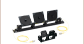
- Align Fiber Collimators to Create Free Space Between Fibers
Click here for more insights into lab practices and equipment.
Align Fiber Collimators to Create Free Space Between Fibers
Two collimators, inserted into a fiber optic setup, provide free-space access to the beam. The first collimator accepts the highly diverging light from the first fiber and outputs a free-space beam, which propagates with an approximately constant diameter to the second collimator. The second collimator accepts the free-space beam and couples that light into the second fiber. Some collimation packages, including the pair used in this demonstration, are designed for use with optical fibers and mate directly to fiber connectors.
Ideally, 100% of the light emitted by the first fiber would be coupled into the second fiber, but some light will always be lost due to reflections, scattering, absorption, and misalignment. Misalignment, typically the largest source of loss, can be minimized using the alignment and stabilization techniques described in this video.
In this demonstration, the first fiber is single mode. The optical power incident on the second collimator, as well as the power output by the second fiber, are measured. When the second fiber is multimode with a 50 µm diameter core, alignment resulted in 91% of the power incident on the second collimator being measured at the fiber output. This value was 86% when the second fiber is single mode. Some differences in collimator designs, and their effects on the characteristics of the collimated beams, are also discussed.
If you would like more information about tips, tricks, and other methods we often use in the lab, we recommend our other Video Insights. In addition, our webinars provide practical and theoretical introductions to our different products.
| Products Featured During Demonstration | ||||
|---|---|---|---|---|
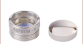
| Fiber-Coupled Laser | Kinematic Mounts | Fiber Adapter Cap (for Power Sensor) |
Single Mode Patch Cable (FC/PC) | Fiber Cable Storage Reels |
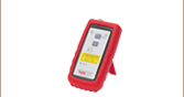
| Triplet Fiber Optic Collimators | Power Sensor | Power Meter | Hybrid Single Mode Patch Cable | 2" Posts |
| Adapter (Mount-to-Collimator) |
SM1 Thread Adapter (for Power Sensor) |
Fiber Connector Cleaner | Step-Index Multimode Patch Cable | Ø1/2" Post Holders |
Date of Last Edit: April 21, 2021
| Posted Comments: | |
Bo Xin
(posted 2023-04-20 16:45:54.91) Hello, I cannot seem to find the clear aperture for the collimators. Related to that, how is your NA defined for a Gaussian beam? Thanks, cdolbashian
(posted 2023-04-26 09:37:53.0) Thank you for reaching out to us with this inquiry. The CA is typically defined as 90% of the size of the lens. The diameter of the visible portion of the lens is ~18mm, and thus the CA would be ~16.2mm.
As far as the NA, this is the NA of the lens used here. We do not explicitly define it for gaussian beams. Ross Harder
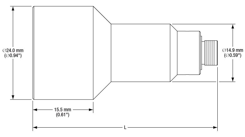
(posted 2023-02-07 13:04:16.91) I think some of these collimators are 24mm in diameter but the product detail says they are compatible with 15mm mount adapters. cdolbashian
(posted 2023-02-17 11:31:12.0) Thank you for reaching out to us with this inquiry. We have a, hopefully, helpful image above in the "overview" tab showing how the AD15F adapter can be used to mount the collimator. I have contacted you directly to elucidate you on this functionality. user
(posted 2021-09-22 11:53:34.517) On your triplet collimators web page, you provide the pointing error, which is very useful to know. Please can you add the same information to the web page for air-spaced doublet collimators ? cdolbashian
(posted 2021-10-15 05:02:06.0) Thank you for reaching out to us with this suggestion! I will pass this suggestion along internally for future web revisions and spec updates! user
(posted 2021-08-13 06:26:43.58) Hi, I have two questions. 1) The theoretical 7.5mm diameter value from this collimator. What is the measured value? Also in the divergence tab, is the plot of the diameter over distance also from calculation? 2) Regarding the beam diameter formula, why is it dependent on the MFD of the fiber? Isn't it just the focal length times the numerical aperture of the fiber? If you consider the variation of MFD of 780HP, it is 5.0um +/- 0.5um, this will give you the output beam between 6.49mm to 7.94mm, how do you say the theoretical value is 7.5mm? Thanks a lot for your answering in advance! cdolbashian
(posted 2021-08-19 03:34:51.0) Thank you for your inquiries here!
1) The measured value depends on the MFD of the fiber used. We use the nominal value of 4.56um when simulating this value of 7.5mm. The diameter data is indeed also from simulation.
2) The NA of a SM fiber is not simply NA = n*Sin(theta), rather the divergence must be calculated via the MFD (https://www.thorlabs.com/newgrouppage9.cfm?objectgroup_id=14204). See question 1 regarding the MFD chosen.
I have reached out to you directly with more explicit answers to your questions!
Thank you for your inquiries! user
(posted 2021-05-10 06:56:35.61) Why is the origin of the CAD models not centered on the optical axis? The lack of a sensible reference point hinders the usability of these files. cdolbashian
(posted 2021-06-04 09:58:37.0) Thank you for your feedback! We will look into updating this in the future. . Mitchell C
(posted 2021-04-15 05:20:07.32) Hi, do these air spaced doublets give better beam quality (M^2) than the cheaper aspheric collimators? I'm particularly interested in 635nm. Thanks YLohia
(posted 2021-04-21 11:26:30.0) Hello, thank you for contacting Thorlabs. While we don't specify beam quality performance for these, we do expect the performance to be better than that of the regular aspheric collimators. For the best possible performance, please see our triplet collimators here: https://www.thorlabs.com/newgrouppage9.cfm?objectgroup_id=5124 Christian Schmidt
(posted 2020-06-16 13:38:25.27) Hello Thorlabs-Team,
regarding collimation and wavefront distortions/M², are the Air-Spaced Doublet Collimators better as the the Triplet Fiber Optic Collimators/Couplers? Esp. if I use the design WL. (In my case I am intrested in TC25APC-633 vs F810APC-635)
Thank you Christian DJayasuriya
(posted 2020-06-24 03:34:20.0) Thank you for your inquiry. The M squared value of a triplet collimator, like the TC25APC-633 is very good, typically around 1.02 or even better. Please see graph on top left under 'Performance' tab on this page for example measurements. The TC collimators are significantly better in terms of M squared values and beam quality in general. Jessica Dipold
(posted 2020-02-28 09:31:29.287) Hello. I would like to know the damage threshold of the f810sma-780 for a cw diode laser at 940nm. Its maximum power is 50W, can it hold?
Thank you! llamb
(posted 2020-03-05 04:11:52.0) Hello Jessica, thank you for contacting Thorlabs. We have not performed conclusive damage threshold testing for this particular wavelength of air-spaced doublet collimators. When considering damage thresholds, you must also consider whether you are collimating out from the fiber, or coupling into it. I have reached out to you directly to discuss your application further. Tyler
(posted 2009-01-27 14:45:07.0) A response from Tyler at Thorlabs to femtor: The collimator will not alter the polarization of the light. So yes, the F810APC-1550 can be used in a system where maintaining the polarization of the light is important. Thank you for submitting your question. femtor
(posted 2009-01-11 10:12:30.0) Dear Sir: I wonder if the F810APC-1550 collimator can be used in a polarization maintaining optical system. If I use the PM FC/APC patch cable with APC-Style connector (P3-1550PM-FC-2) to connect this collimator to a PM optical system, will the system still be PM? Tyler
(posted 2008-11-05 16:03:36.0) A response from Tyler at Thorlabs to makoto.chang: These collimation packages can indeed be used to couple light into an optical fiber. A member of our technical support department will contact you for more details about your application and some possible solutions. Thank you for considering a Thorlabs collimation package. makoto.chang
(posted 2008-11-04 21:22:51.0) Dear Sir:
I saw the description in your website, "These packages can also be used to couple a free space laser beam into an optical fiber, please call our technical support group if you would like assistance with this application."
Can these products be used for optical spectrum measurement of 1550nm laser chip on wafer? Can you give me more information and suggest a part number for this application?
Thanks.
Makoto Chang techsupport
(posted 2008-08-06 17:43:36.0) We can certainly design a new product for such an application and this kind of input is extremly helpful for us.
If you have a need for an F810 collimator that could be used around 405nm please let us know and we will look for a custom solution on short term.
In addition any thoughts or comments with respect to the general need for such an item are highly welcome and will help us to decide if it should be a custom build solution or a product that is offered as a standard part which ships same day from stock. ghegenbart
(posted 2008-07-31 10:22:45.0) A response from Gerald at Thorlabs: The NA of the F810FC-543 collimation package optics is 0.26. Thus using it with a 0.27 NA fiber will not lead to optimum results. If you use the package with the AFS50/125Y multi mode fiber having 0.22 NA the beam diameter just behind the optics will be about 15 mm at a divergence of about 0.72 mrad (at 543 nm). Furthermore usage of the F810 type collimation packages at 405 nm is not recommended. The reasons are a decrease of transmission of the glass type used for one of the lenses and an increased reflection of the AR coating below 420 nm. Therefore we do not offer doing a special alignement of these collimation packages for 405 nm. thomas.juffmann
(posted 2008-07-30 10:54:47.0) Hello,
how much would the divergence increase if I used a multimode fiber (e.g. M31L03 )? How well would that work for a 405nm laser beam?
Thank you for your help,
Thomas Tyler
(posted 2008-06-03 10:21:23.0) A response from Tyler at Thorlabs The F810APC-1550 collimator is factory aligned for 1550 nm light and as a result will not produce a well collimated beam when used with 1650 nm light. You could contact our technical support staff and request a quote for a collimator aligned for 1650 nm or try a CFC-5-C. The CFC-5-C allows the user to adjust the position of the lens along the optic axis for optimum collimation of the beam. In addition, the lens used in the CFC-5-C has an NA of 0.53, which is suitable for use with a fiber that has a divergence angle of 30 degrees. The AR coating on the lens used in the CFC-5-C is only specified to 1550 nm. However, the reflections are still less than 0.5% per surface at 1650 nm so it is reasonable to use the collimator at 1650 nm. hongxingqi
(posted 2008-06-02 03:36:15.0) I need collimate a DFB laser beam, the wavelength of which is 1650nm. The angle of divergence for my DFB laser is 30 degree, and the fiber connector is FC/APC, I wonder if the F810APC-1550 is right for my laser. technicalmarketing
(posted 2007-11-19 08:58:48.0) The F810SMA-543 collimators can be purchased online or by calling our sales support staff at 1-973-579-7227. zwleevivi
(posted 2007-11-17 00:16:16.0) we need two F810SMA-543 collimators,how should we get them as quickly as we can.please send an e-mail to me ,thank you.Chutianlaser Wuhan China
vivilee |
Fiber Collimator Selection Guide
Click on the collimator type or photo to view more information about each type of collimator.
| Type | Description | |
|---|---|---|
| Fixed FC, APC, or SMA Fiber Collimators | 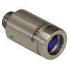 |
These fiber collimation packages are pre-aligned to collimate light from an FC/PC-, FC/APC-, or SMA-terminated fiber. Each collimation package is factory aligned to provide diffraction-limited performance for wavelengths ranging from 405 nm to 4.55 µm. Although it is possible to use the collimator at detuned wavelengths, they will only perform optimally at the design wavelength due to chromatic aberration, which causes the effective focal length of the aspheric lens to have a wavelength dependence. |
| Air-Spaced Doublet, Large Beam Collimators | 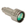 |
For large beam diameters (Ø5.3 - Ø8.5 mm), Thorlabs offers FC/APC, FC/PC, and SMA air-spaced doublet collimators. These collimation packages are pre-aligned at the factory to collimate a laser beam propagating from the tip of an FC or SMA-terminated fiber and provide diffraction-limited performance at the design wavelength. |
| Triplet Collimators | 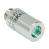 |
Thorlabs' High Quality Triplet Fiber Collimation packages use air-spaced triplet lenses that offer superior beam quality performance when compared to aspheric lens collimators. The benefits of the low-aberration triplet design include an M2 term closer to 1 (Gaussian), less divergence, and less wavefront error. |
| Achromatic Collimators for Multimode Fiber | 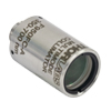 |
Thorlabs' High-NA Achromatic Collimators pair a meniscus lens with an achromatic doublet for high performance across the visible spectrum with low spherical aberration. Designed for use with high-NA multimode fiber, these collimators are ideal for Optogenetics and Fiber Photometry applications. |
| Reflective Collimators | 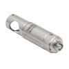 |
Thorlabs' metallic-coated Reflective Collimators are based on a 90° off-axis parabolic mirror. Mirrors, unlike lenses, have a focal length that remains constant over a broad wavelength range. Due to this intrinsic property, a parabolic mirror collimator does not need to be adjusted to accommodate various wavelengths of light, making them ideal for use with polychromatic light. Our reflective collimators are ideal for collimating single mode fiber but are not recommended for coupling into single mode fiber. We also offer a compact version of the protected-silver-coated reflective collimators that is directly compatible with our 16 mm cage system. |
| FiberPorts |  |
These compact, ultra-stable FiberPort micropositioners provide an easy-to-use, stable platform for coupling light into and out of FC/PC, FC/APC, or SMA terminated optical fibers. It can be used with single mode, multimode, or PM fibers and can be mounted onto a post, stage, platform, or laser. The built-in aspheric or achromatic lens is available with five different AR coatings and has five degrees of alignment adjustment (3 translational and 2 pitch). The compact size and long-term alignment stability make the FiberPort an ideal solution for fiber coupling, collimation, or incorporation into OEM systems. |
| Adjustable Fiber Collimators |  |
These collimators are designed to connect onto the end of an FC/PC, FC/APC, or SMA connector and contain an AR-coated aspheric lens. The distance between the aspheric lens and the tip of the fiber can be adjusted to compensate for focal length changes or to recollimate the beam at the wavelength and distance of interest. |
| Achromatic Fiber Collimators with Adjustable Focus | 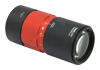 |
Thorlabs' Achromatic Fiber Collimators with Adjustable Focus are designed with an effective focal length (EFL) of 20 mm, 40 mm, or 80 mm, have optical elements broadband AR coated for one of three wavelength ranges, and are available with FC/PC, FC/APC, or SMA905 connectors. A four-element, air-spaced lens design produces superior beam quality (M2 close to 1) and less wavefront error when compared to aspheric lens collimators. These collimators can be used for free-space coupling into a fiber, collimation of output from a fiber, or in pairs for collimator-to-collimator coupling over long distances, which allows the beam to be manipulated prior to entering the second collimator. |
| Zoom Fiber Collimators | 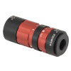 |
These collimators provide a variable focal length between 6 and 18 mm, while maintaining the collimation of the beam. As a result, the size of the beam can be changed without altering the collimation. This universal device saves time previously spent searching for the best suited fixed fiber collimator and has a very broad range of applications. They are offered with FC/PC, FC/APC, or SMA905 connectors with three different antireflection wavelength ranges to choose from. |
| Single Mode Pigtailed Collimators | 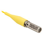 |
Our single mode pigtailed collimators come with one meter of fiber, consist of an AR-coated aspheric lens pre-aligned with respect to a fiber, and are collimated at one of eight wavelengths: 532 nm, 633 nm, 780 nm, 850 nm, 1030 nm, 1064 nm, 1310 nm, or 1550 nm. Although it is possible to use the collimator at any wavelength within the coating range, the coupling loss will increase as the wavelength is detuned from the design wavelength. |
| Polarization Maintaining Pigtailed Collimators | 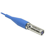 |
Our polarization maintaining pigtailed collimators come with one meter of fiber, consist of an AR-coated aspheric lens pre-aligned with respect to a fiber, and are collimated at one of six wavelengths: 532 nm, 830 nm, 1030 nm, 1064 nm, 1310 nm, or 1550 nm. Custom wavelengths and connectors are available as well. A line is engraved along the outside of the housing that is parallel to the slow axis. As such, it can be used as a reference when polarized light is launched accordingly. Although it is possible to use the collimator at any wavelength within the coating range, the coupling loss will increase as the wavelength is detuned from the design wavelength. |
| GRIN Fiber Collimators |  |
Thorlabs offers gradient index (GRIN) fiber collimators that are aligned at a variety of wavelengths from 630 to 1550 nm and have either FC terminated, APC terminated, or unterminated fibers. Our GRIN collimators feature a Ø1.8 mm clear aperture, are AR-coated to ensure low back reflection into the fiber, and are coupled to standard single mode or graded-index multimode fibers. |
| GRIN Lenses |  |
These graded-index (GRIN) lenses are AR coated for applications at 630, 830, 1060, 1300, or 1560 nm that require light to propagate through one fiber, then through a free-space optical system, and finally back into another fiber. They are also useful for coupling light from laser diodes into fibers, coupling the output of a fiber into a detector, or collimating laser light. Our GRIN lenses are designed to be used with our Pigtailed Glass Ferrules and GRIN/Ferrule sleeves. |
| Item # | Alignment Wavelengtha |
Lens AR Coating |
Waist Diameterb |
Waist Distancec |
Full-Angle Divergenced |
Theoretical Divergence |
NA | Focal Lengthe |
Damage Threshold |
L | Drawingf | Connector Type |
|---|---|---|---|---|---|---|---|---|---|---|---|---|
| F810APC-405 | 405 nm | 405 nm Rabs < 0.25% |
5.3 mm | 32.52 mm | 0.009° | 0.27 | 33.9 mm | - | 45.2 mm (1.78") |
 Click for Details |
FC/APC | |
| F810FC-405 | 45.0 mm (1.77") |
FC/PC | ||||||||||
| F810SMA-405 | 1.86" (47.3 mm) |
SMA |
| Item # | Alignment Wavelengtha |
Lens AR Coating | Waist Diameterb | Waist Distancec | Full-Angle Divergenced | Theoretical Divergence | NA | Focal Lengthe |
Damage Thresholdf | L | Drawingg | Connector Type |
|---|---|---|---|---|---|---|---|---|---|---|---|---|
| F810APC-543 | 543 nm | 350 - 700 nm Ravg < 0.5% |
6.4 mm | 34.81 mm | 0.006° | 0.26 | 34.74 mm | 7.5 J/cm2 | 45.2 mm (1.78") |
Click for Details |
FC/APC | |
| F810FC-543 | 45.0 mm (1.77") |
FC/PC | ||||||||||
| F810SMA-543 | 1.88" (47.8 mm) |
SMA |
| Item # | Alignment Wavelengtha |
Lens AR Coating | Waist Diameterb | Waist Distancec | Full-Angle Divergenced | Theoretical Divergence | NA | Focal Lengthe |
Damage Threshold | L | Drawingf | Connector Type |
|---|---|---|---|---|---|---|---|---|---|---|---|---|
| F810APC-635 | 635 nm | 350 - 700 nm Ravg < 0.5% |
6.7 mm | 35.16 mm | 0.007° | 0.25 | 35.41 mm | - | 45.8 mm (1.80") |
Click for Details |
FC/APC | |
| F810FC-635 | 45.6 mm (1.80") |
FC/PC | ||||||||||
| F810SMA-635 | 1.90" (48.4 mm) |
SMA |
| Item # | Alignment Wavelengtha |
Lens AR Coating | Waist Diameterb | Waist Distancec | Full-Angle Divergenced | Theoretical Divergence | NA | Focal Lengthe |
Damage Threshold | L | Diagramf | Connector Type |
|---|---|---|---|---|---|---|---|---|---|---|---|---|
| F810APC-780 | 780 nm | 650 - 1050 nm Ravg < 0.5% |
7.5 mm | 36.10 mm | 0.008° | 0.25 | 36.01 mm | - | 41.4 mm (1.63") |
Click for Details |
FC/APC | |
| F810FC-780 | 46.0 mm (1.81") |
FC/PC | ||||||||||
| F810SMA-780 | 1.93" (49.0 mm) |
SMA |
| Item # | Alignment Wavelengtha |
Lens AR Coating |
Waist Diameterb |
Waist Distancec |
Full-Angle Divergenced |
Theoretical Divergence |
NA | Focal Lengthe |
Damage Threshold | L | Diagramf | Connector Type |
|---|---|---|---|---|---|---|---|---|---|---|---|---|
| F810APC-850 | 850 nm | 650 - 1050 nm Ravg < 0.5% |
7.8 mm | 36.18 mm | 0.008° | 0.25 | 36.20 mm | - | 46.6 mm (1.83") | Click for Details |
FC/APC | |
| F810FC-850 | 46.4 mm (1.82") | FC/PC | ||||||||||
| F810SMA-850 | 48.6 mm (1.91") | SMA |
| Item # | Alignment Wavelengtha |
Lens AR Coating |
Waist Diameterb |
Waist Distancec |
Full-Angle Divergenced |
Theoretical Divergence |
NA | Focal Lengthe |
Damage Threshold | L | Diagramf | Connector Type |
|---|---|---|---|---|---|---|---|---|---|---|---|---|
| F810APC-980 | 980 nm | 650 - 1050 nm Ravg < 0.5% |
7.8 mm | 36.53 mm | 0.009° | 0.25 | 36.47 mm | - | 46.9 mm (1.85") | Click for Details |
FC/APC | |
| F810FC-980 | 46.7 mm (1.84") | FC/PC | ||||||||||
| F810SMA-980 | 48.9 mm (1.93") | SMA |
| Item # | Alignment Wavelengtha |
Lens AR Coating | Waist Diameterb | Waist Distancec | Full-Angle Divergenced |
Theoretical Divergence | NA | Focal Lengthe |
Damage Thresholdf | L | Diagramg | Connector Type |
|---|---|---|---|---|---|---|---|---|---|---|---|---|
| 1064 nm | 1050 - 1074 nm Ravg < 0.25% |
8.0 mm | 36.66 mm | 0.010° +0.010°/-0.00° | 0.25 | 36.60 mm | 7.5 J/cm2 | (1.85") |
Click for Details |
FC/APC | ||
| F810FC-1064 | 46.8 mm (1.84") |
FC/PC | ||||||||||
| F810SMA-1064 | 49.5 mm (1.95") |
SMA |
| Item # | Alignment Wavelengtha |
Lens AR Coating | Waist Diameterb | Waist Distancec | Full-Angle Divergenced | Theoretical Divergence | NA | Focal Lengthe |
Damage Threshold | L | Diagramf | Connector Type |
|---|---|---|---|---|---|---|---|---|---|---|---|---|
| F810APC-1310 | 1310 nm | 1050 - 1620 nm Ravg < 0.5% |
6.7 mm | 36.96 mm | 0.014° | 0.24 | 36.90 mm | - | 47.2 mm (1.86") |
Click for Details |
FC/APC | |
| F810FC-1310 | 46.9 mm (1.84") |
FC/PC | ||||||||||
| F810SMA-1310 | 1.95" (49.6 mm) |
SMA |
| Item # | Alignment Wavelengtha |
Lens AR Coating | Waist Diameterb | Waist Distancec | Full-Angle Divergenced | Theoretical Divergence |
NA | Focal Lengthe |
Damage Threshold | L | Diagramf | Connector Type |
|---|---|---|---|---|---|---|---|---|---|---|---|---|
| F810APC-1550 | 1550 nm | 1050 - 1620 nm Ravg < 0.5% |
7.0 mm | 37.20 mm | 0.016° | 0.24 | 37.13 mm | - | 46.9 mm (1.85") |
Click for Details |
FC/APC | |
| F810FC-1550 | 46.9 mm (1.85") |
FC/PC | ||||||||||
| F810SMA-1550 | 1.96" (49.8 mm) |
SMA |
|
Item #
|
Alignment Wavelengtha |
Lens AR Coating | Waist Diameterb | Waist Distancec | Full-Angle Divergenced | Theoretical Divergence | NA | Focal Lengthe |
Damage Threshold | L | Diagramf | Connector Type |
|---|---|---|---|---|---|---|---|---|---|---|---|---|
| F810APC-2000 | 2.0 µm | 1.8 - 2.4 µm Ravg < 0.5% |
7.3 mm | 37.45 mm | 0.02° | 0.24 | 37.52 mm | - | 47.1 mm (1.86") |
Click for Details |
FC/APC | |
| F810FC-2000 | 47.5 mm (1.87") |
FC/PC | ||||||||||
| F810SMA-2000 | 50.3 mm (1.98") |
SMA |