 Products Home
Mechanical Essentials Kit: Bases and Post Holders
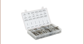
- Kit Contains 100 Pieces
- Stackable, Heavy-Duty Welded Steel Cabinet Frame
- Cabinet Frame can be Wall Mounted or Stacked
- Equipped with Easy-to-Read Labels
ESK01
Kit Components


Please Wait
Features
- Imperial and Metric Kits
- Frame Dimensions (L x W x H): 17.13" x 11.11" x 11.08" (435.0 mm x 282.3 mm x 281.3 mm)
- Drawer Dimensions (L x W x H): 10.89" x 5.50" x 3.15" (268 mm x 132 mm x 78 mm)
- Clear Labels with Product Icons Facilitate the Process of Locating the Desired Part
- Greater than 10% Savings Over Individual Items

Click to Enlarge
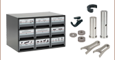
Slots on the rear of the case allow for wall mounting.
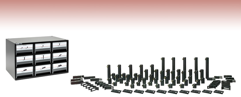
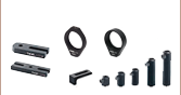
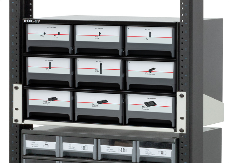
This Bases and Post Holders Essentials Kit contains all of the commonly used post holders, bases, and table clamps in easy-to-use, labeled compartments. The large variety of sizes provides the maximum amount of flexibility when breadboarding an optical system. Refer to the Contents tab above for detailed information about the components included with the imperial and metric versions of this kit. This kit is best used in conjunction with the ESK16 (ESK16/M) Post and Accessory Essentials Kit.
Application Idea: Use the RK4101 rack shelf to organize our ESK Series Essential Kits within our RK3884 standard 19" rack. Post-mounted optical elements can be stored in the 19" rack with the use of the RK4102 rack shelf as shown in the photo to the left.
All ESK Series Essentials Kits are equipped with easy-to-read labels complete with product icons, allowing quick access to all products housed within the kits. All ESK Series Cabinets have slots in the rear of the case, shown to the right, for wall mounting and feature indentations on the top and four feet on the bottom for stable stacking.
| Item # in ESK01 (Imperial) |
Item # in ESK01/M (Metric) |
Description | Image | Quantity |
|---|---|---|---|---|
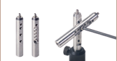
| PH1 | PH30/M | Post Holder with Spring-Loaded Hex Locking Thumbscrew, L= 1" (30 mm) |  Click to Enlarge |
10 |
| PH1.5 | PH40/M | Post Holder with Spring-Loaded Hex Locking Thumbscrew, L= 1.5" (40 mm) |  Click to Enlarge |
10 |
| PH2 | PH50/M | Post Holder with Spring-Loaded Hex Locking Thumbscrew, L= 2" (50 mm) |  Click to Enlarge |
10 |
| PH3 | PH75/M | Post Holder with Spring-Loaded Hex Locking Thumbscrew, L= 3" (75 mm) | 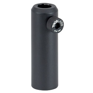 Click to Enlarge |
10 |
| PH4 | PH100/M | Post Holder with Spring-Loaded Hex Locking Thumbscrew, L= 4" (100 mm) | 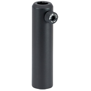 Click to Enlarge |
5 |
| PH6 | PH150/M | Post Holder with Spring-Loaded Hex Locking Thumbscrew, L= 6" (150 mm) | 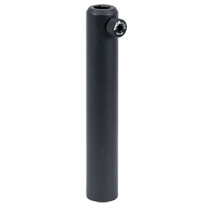 Click to Enlarge |
5 |
| CL5 | L-Shape General Purpose Table Clamp | 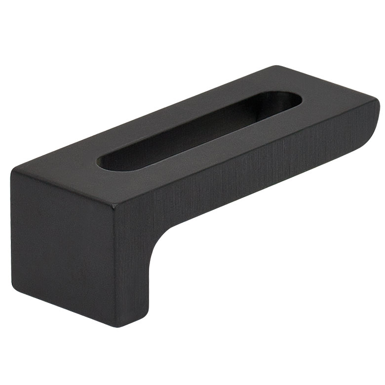 Click to Enlarge |
20 | |
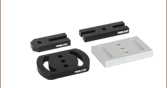
| BA1 | BA1/M | Mounting Base, 1" x 3" x 3/8" (25 mm x 75 mm x 10 mm) | 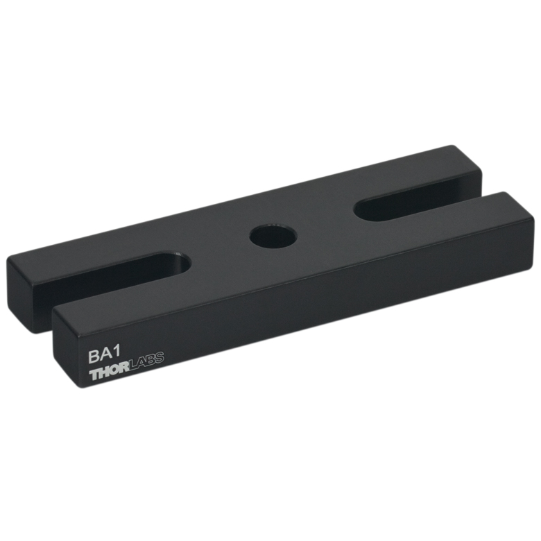 Click to Enlarge |
10 |
| BA1S | BA1S/M | Mounting Base, 1" x 2.3" x 3/8" (25 mm x 58 mm x 10 mm) | 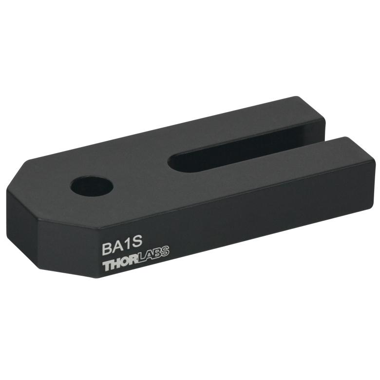 Click to Enlarge |
10 |
| BA2 | BA2/M | Mounting Base, 2" x 3" x 3/8" (50 mm x 75 mm x 10 mm) | 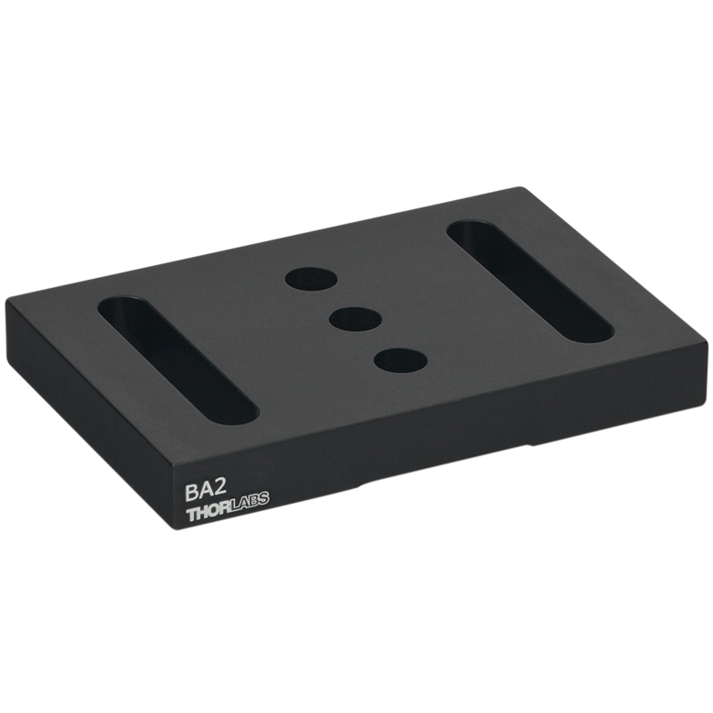 Click to Enlarge |
10 |
| ST9 | 9 Drawer Stackable Cabinet | 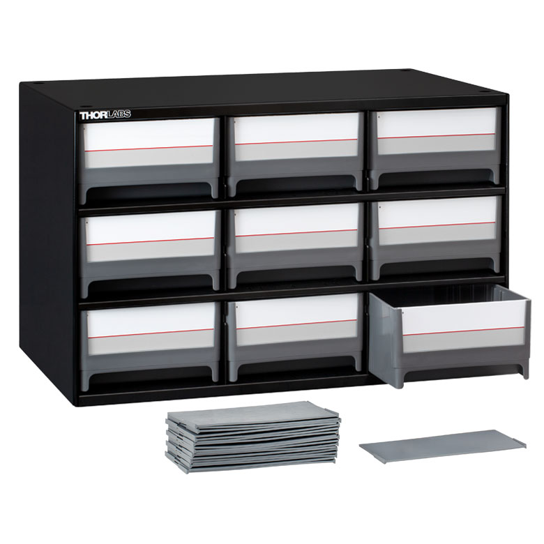 Click to Enlarge |
1 | |

Insights into Best Lab Practices
Scroll down to read about a few things we consider when setting up lab equipment.
- Washers: Using Them with Optomech
- Bases: For Stability Orient the Side with the Undercut Down
- Post Holders: Rectangular Channel in the Inner Bore
Click here for more insights into lab practices and equipment.
Washers: Using Them with Optomech
Click to Enlarge
Figure 2: Install washers before inserting bolts into slots to protect the slot from damage. The rounded, smooth side of the washer should be placed against the slot, and the rough, flat side should be in contact with the bolt head. The smooth surface is designed to translate easily across the anodized surface, without harming it. The BA2 base is illustrated.
Click to Enlarge
Figure 1: The diameter of the washer is 35% larger than that of the bolt head. This results in over a six fold increase in overlap area with the slot of a BA2 base. By distributing the force of the bolt over a larger area, the washer help prevent gouging of the slot.
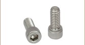
The head of a standard cap screw is not much larger than the major diameter of the thread (Figure 1). For example, a 1/4"-20 screw has a head diameter between 0.365" and 0.375" and the clearance hole diameter for the threads is 0.264".
When the screw is tightened directly through the clearance hole to secure the device, the force is applied to the edge of the through hole, often cutting into the material (Figure 1).
Once the material is permanently deformed, the screw head will want to fall back into the gouged groove, thereby moving the device back to that location when attempting to make fine adjustments.
A device with a circular through hole is not meant to translate around the screw thread so the deformation is not expected to be a problem.
However, a slot should provide the ability to secure the device anywhere along the length for the lifetime of the part. Using a washer distributes the force away from the slot edge to decrease the chance of deforming the slot and extending the lifetime of the part. Figure 1 illustrates the difference a washer can make. The contact area between the slot of a BA2 base and a 0.27" diameter cap screw is 0.010 in2. When a 0.5" diameter washer is used the contact area is 0.064 in2, which is over six times larger.
When using a Thorlabs washer, there are two distinct sides (Figure 2). One side is flat and rough and the other is curved and polished. The curved and polished side should be placed against the device, which has an anodized surface.
As the screw tightens, the screw head can force the washer to spin against the anodized coating.
If the flat side is pressed down against the anodization, the friction created by the rough flat side can scratch the anodized aluminum. However, if the curved side is facing down, the smooth surface has less friction leading to less scratches and extending the visual appearance of the device.
Date of Last Edit: Dec. 4, 2019
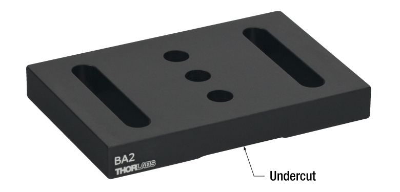
Bases: For Stability Orient the Side with the Undercut Down
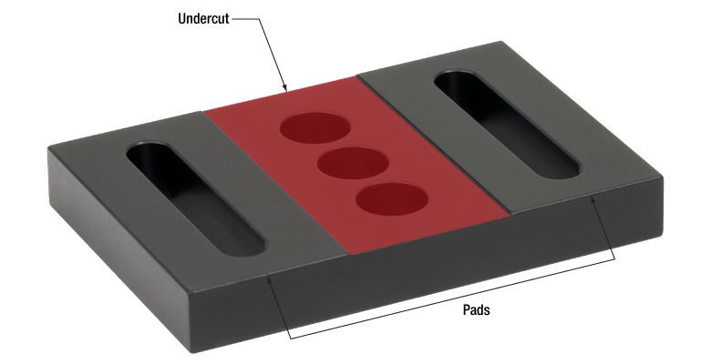
An undercut is machined into the bottom surface of bases like the BA2 (Figures 3 and 4). The undercut creates feet, which are called pads. For maximum stability, the base should be oriented with its pads in contact with the table or breadboard.
The top surface of the base does not have an undercut and is the intended mounting surface for components.
Mounting the base upside down could result in the base rocking on the table or breadboard, or the base may exhibit other mechanical instability.
The Pads are Flatter than the Top Surface
The undercut is key to the flatness of the pads. The pads are machined flat after the undercut is made.
Friction heats the pads during the processing step that provides them with a maximally flat profile. By reducing the surface area of the pads, the undercut reduces the amount of heat generated during this step.
It is beneficial to minimize the heat generated during machining. Metal expands when heated, and the uneven heating that occurs during machining can distort the dimensions of the part. If the dimensions of the part are distorted during machining, the part can be left with high spots and other undesirable features after it cools. This can cause instability and misalignment when using the part.
Precision Instruments and Devices have Pads
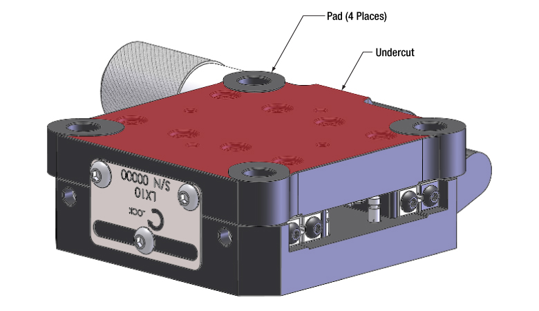
Another example of a component with pads is the LX10 linear stage shown in Figure 5.
Click to Enlarge
Figure 5: Pads machined into Thorlabs' devices improve their stability when bolted in place. The pads are highly flat and project above the undercut region, which is highlighted red. The undercut limits the contact area with the table or breadboard.
Click to Enlarge
Figure 4: This view of the bottom shows the undercut highlighted in red. By removing this material, the pads can be made maximally flat.
Click to Enlarge
Figure 3: For optimal stability, the base should be mounted with the undercut facing the optical table or breadboard.
Date of Last Edit: Dec. 9, 2019
Post Holders: Rectangular Channel in the Inner Bore
Click to Enlarge
Figure 7: Top view. The three contact locations between the post and post holder, highlighted in red, prevent the post from translating or rotating around the X or Y axes. Friction resists the post's translation and rotation around the Z axis.

Click to Enlarge
Figure 6: A channel with sharp edges is machined into the inner bore of Thorlabs' post holders.
Figure 8: A broach, such as the one illustrated above, has a row of teeth, the next taller than the previous. With the teeth in contact with the material, a machine pulls the broach across the surface. Each tooth removes a small amount of material, and the depth of the channel created by the broach equals the overall difference in tooth height.
All of Thorlabs' post holders include a channel, with straight parallel edges, running the length of the inner bore (Figure 6). Tightening the setscrew pushes the post against the two edges of the channel (Figure 7). Since the edges of the channel are separated by a wide distance, approximately half the inner diameter of the post holder, the seating of the post against the channel's edges is stable and repeatable.
Contact with the two edges of the channel eliminates four of the post's six degrees of freedom, since the edges block the post from translating along or rotating around either the Y or Z axis. In addition, the friction between the side of the post and the edges of the channel resists the post's movement along and around the X axis, which are the post's two remaining degrees of freedom.
Without the channel in the inner bore, there would be a single line of contact between the post and post holder. The position of the post would not be stable, since the post would be free to rotate around the Z axis and shift along the Y axis.
Even if this instability resulted in submicron-scale unwanted shifts in each component's position in an optical setup, the cumulative effect could have a significant negative impact on system performance. In addition, more frequent realignment of the system could be required.
Broaching
The channel's edges must be straight and free of bumps and roughness to hold the post stable. These post holders have straight, sharp edges when examined on a micron scale. If the edges are not completely linear, the post might rock in the holder, and / or it may not be possible to repeatably position the post in the holder.
The smooth, straight edges of the channel are achieved using a machining process called broaching. A broach (Figure 8) resembles a saw whose teeth increase in height along its length.
As the broach is pulled along a surface, each tooth removes a small amount of material. The total depth of the channel cut by the broach equals to the overall difference in tooth height (H2 - H1).
Compared with other approaches for creating channels, broaching is preferred due to its ability to provide straight profiles while being compatible with high-volume production.
Date of Last Edit: Dec. 11, 2019
| Posted Comments: | |
peter.bechtold
(posted 2017-06-14 08:31:32.333) Hey Thorlabs team! Great work, keep it up. We do not use your kits, but make up our own kits using Thorlabs equipment. But we would like to use your kind of labels used on the optomechanic kits (the small pictograms + article numbering). Are those available anywhere? Thanks and BR, Peter. nbayconich
(posted 2017-06-26 05:22:01.0) Thank you for contacting Thorlabs. We can provide these labels. I will reach out to you directly with more information. |