 Products Home / Optical Elements / Optical Lenses / Achromatic Lenses / Cemented Achromatic Doublets / Unmounted Achromatic Doublets, AR Coated: 400 - 700 nm
Unmounted Achromatic Doublets, AR Coated: 400 - 700 nm
- Achromatic Performance with AR Coating for 400 - 700 nm
- Multi-Element Design Minimizes Spot Size
- Custom Achromatic Optic Available
AC508-180-A
f = 180 mm, Ø2"
AC254-080-A
f = 80 mm, Ø1"
AC127-050-A
f = 50 mm, Ø1/2"
AC080-016-A
f = 16 mm, Ø8 mm
AC060-010-A
f = 10 mm, Ø6 mm


Please Wait
| General Specifications | ||
|---|---|---|
| Design Wavelengths | 486.1 nm, 587.6 nm, and 656.3 nm | |
| AR Coating Range | 400 - 700 nm | |
| Reflectance Over AR Coating Range (0° AOI) |
Ravg < 0.5% | |
| Diameters Available | 2 mm, 5 mm, 6 mm, 6.35 mm, 8 mm, 1/2", 1", 30 mm, and 2" |
|
| Diameter Tolerance | +0.0 / -0.1 mma | |
| Focal Length Tolerance | ±1%b | |
| Surface Quality | 40-20 Scratch-Digc | |
| Spherical Surface Powerd,e | 3λ/2 | |
| Spherical Surface Irregularity (Peak to Valley)e |
λ/4 | |
| Centration | <3 arcminf | |
| Clear Aperture | >90% of Diameter | |
| Damage Thresholdg | Pulsed | 0.5 J/cm2 (532 nm, 10 ns Pulse, 10 Hz, Ø0.566 mm) |
| CWh | 300 W/cm (532 nm, Ø1.000 mm) | |
| Operating Temperature | -40 °C to 85 °C | |
 Zemax Files Zemax Files |
|---|
| Click on the red Document icon next to the item numbers below to access the Zemax file download. Our entire Zemax Catalog is also available. |

| Achromatic Doublet Selection Guide | |
|---|---|
| Unmounted Lenses | Mounted Lenses |
| Visible (400 - 700 nm) | Visible (400 - 700 nm) |
| Extended Visible (400 - 1100 nm) | Extended Visible (400 - 1100 nm) |
| Near IR (650 - 1050 nm) | Near IR (650 - 1050 nm) |
| IR (1050 - 1700 nm) | IR (1050 - 1700 nm) |
| Achromatic Doublet Kits | |
Features
- AR Coated for the 400 - 700 nm Range
- Positive Doublet Sizes from Ø2 mm to Ø2"
- Negative Doublet Sizes from Ø1/2" to Ø2"
- 4 to 1000 mm Focal Lengths for Positive Doublets
- -20 to -100 mm Focal Lengths for Negative Doublets
- Custom Achromatic Optics Available
Thorlabs' cemented Achromatic Doublets are optimized to provide excellent performance in the visible region. Our design for the achromatic doublets uses the helium "d" line (587.6 nm, yellow) and the hydrogen "F" (486.1 nm, blue/green) and "C" (656.3 nm, red) lines since these wavelengths reasonably represent the visible spectrum and are used to define the Abbe Number, Vd, of a material.
To see how the performance of achromatic doublets compares to single lenses, refer to the Application tab above. In addition, the Performance tab gives examples of how the performance of achromatic doublets can be analyzed by downloading the Zemax® files found by clicking the document icon next to the appropriate part number below.
For best performance, the side of the lens with the largest radius of curvature (flattest side) should face away from the collimated beam. Doublets Ø1/2" and larger are engraved with the item # on their edge, oriented so that the text is right-side up when the flattest side of the lens is the bottom surface. Please see the diagram under the reference drawing link below for additional details.
Recommended lens mounts are given in the text under each table below. Alternatively, you can choose an appropriate mount from our entire selection of fixed diameter lens mounts, self-centering adjustable lens mounts, and adjustable lens mounts. When choosing a lens mount, make sure the mount can accommodate the diameter and edge thickness specifications of the lens. The achromatic doublets featured on this page are also available mounted. For applications in wavelength regimes less than 410 nm, Thorlabs’ air-gap UV doublets provide excellent performance down to 240 nm.
In the specification tables below, a positive radius of curvature indicates that the surface is opening to the right when the lens is oriented as shown in the reference drawing; a negative radius of curvature indicates that the surface is opening to the left. Both the positive and negative lenses have an infinite conjugate ratio (i.e., if a diverging light source is placed one focal length away from the flatter side of the lens, the light rays emerging from the curved side will be collimated).
Custom Achromatic Lenses
Thorlabs' optics business unit has a wide breadth of manufacturing capabilities that allow us to offer a variety of custom achromatic optics for both OEM sales and low quantity one-off orders. Achromatic optics with customer-defined sizes, focal lengths, substrate materials, cement materials, and coatings are all available as customs. In addition, we can offer optics that exceed the specifications of our stock catalog offerings. To receive more information or inquire about a custom order, please contact Tech Support.
Detailed information regarding each achromatic doublet can be found in the Zemax® files included with the support documents for each doublet. Below are some examples of how the performance of these lenses can be examined using the Zemax® files.
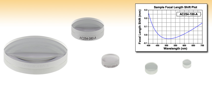
Focal Shift vs. Wavelength
Thorlabs' achromatic doublets are optimized to provide a nearly constant focal length across a broad bandwidth. This is accomplished by utilizing a multi-element design to minimize the chromatic aberration of the lens. Dispersion in the first (positive) element of the doublet is corrected by the second (negative) element, resulting in better broadband performance than spherical singlets or aspheric lenses. The graph below shows the paraxial focal shift as a function of wavelength for the AC254-400-A, which is a 400 mm focal length, Ø25.4 mm visible achromatic doublet.
Click to Enlarge
Figure 1
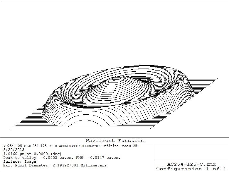
Wavefront Error and Spot Size
Thorlabs' spherical doublet lenses have been corrected for various aberrations, including spherical aberration, chromatic aberration, and coma. One way of displaying the theoretical level of correction is through plots of wavefront error and ray traces to determine spot size. For example, in Figure 2, a plot of wavefront at the image plane reveals information regarding aberration correction by using the AC254-125-C. In this example, the wavefront error is theoretically on the order of 3/100 of a wave. This indicates that the optical path length difference (OPD) is extremely small for arrays going through the center of the lens and at nearly full aperture.
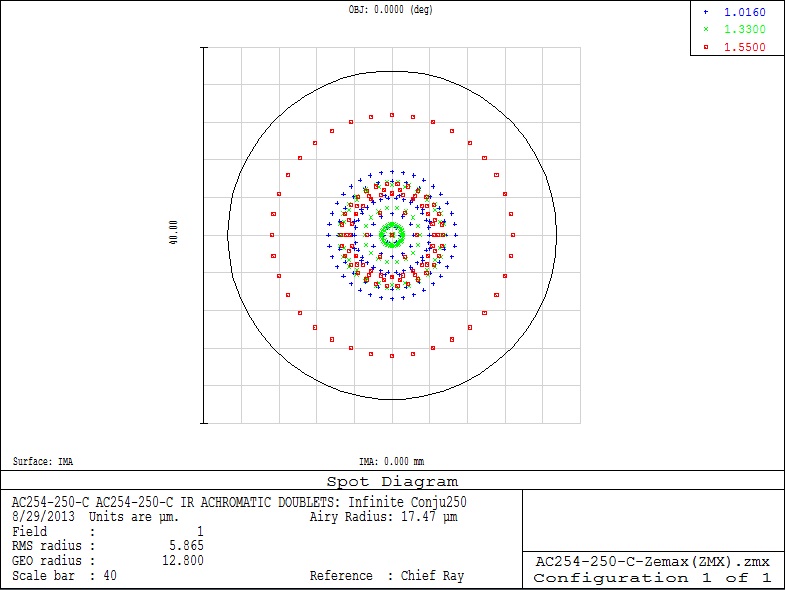
A ray trace for spot size at the image plane of the AC254-250-C is shown below in Figure 3. In this near IR achromatic doublet, the design wavelengths (706.5 nm, 855 nm and 1015 nm) have each been traced through the lens and are represented by different colors. The circle surrounding the distribution of ray intercepts represents the diameter of the Airy disk. If the spot is within the Airy disk, the lens is typically considered to be diffraction limited. Since the spot size is drawn using geometric ray tracing, spots much smaller than the Airy disk are not achievable due to diffraction.
Click to Enlarge
Figure 2
Click to Enlarge
Figure 3
Understanding Modulation Transfer Function, MTF
MTF image quality is an important characteristic of lenses. A common way to measure this is by using contrast. A plot of the modulation transfer function is used as both a theoretical and experimental description of image quality. The MTF of a lens describes its ability to transfer contrast from an object to an image at various resolution levels. Typically, a resolution target made up of black and white lines at various spacings is imaged and contrast can be measured. Contrast at 100% would consist of perfectly black and white lines. As the contrast diminishes, the distinction between lines begins to blur. A plot of MTF shows the percentage of contrast as the spacing between these lines decreases. The spacing between the lines at the object is usually represented as spatial frequency given in cycles/mm.
MTF curves calculated in Zemax® typically present a weighted average with contributions from multiple wavelengths and are known as polychromatic MTF curves. Since shorter and longer wavelengths will have different resolution limits, and hence different individual MTF curves, quantitatively different polychromatic MTF curves may be produced depending on the wavelengths included in the curve's calculation.
Click to Enlarge
Figure 4
The chart shows the theoretical MTF for our Ø25.4 mm, f=200 mm near IR achromatic doublet. The contrast is around 83% at a spatial frequency of about 20 cycles/mm. This represents 83% contrast at 0.05 mm spacings between lines. Theoretical MTF shows how well a design can perform if the optic was built exactly to the design dimensions. In reality, most optics fall short of the theoretical due to manufacturing tolerances.
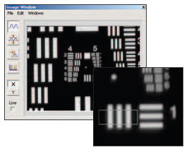
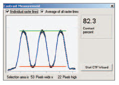
The screen captures to the right and left are actual measurements taken using a USAF 1951 resolution chart as the object.
For the target selected, the contrast measured 82.3%.
Achromatic Doublet Lenses have far superior optical performance to Singlet Lenses. In addition, they offer better broadband and off-axis performance than Aspheric Lenses. Whether your application has demanding imaging requirements or laser beam manipulation needs, these doublets should be considered.
Achieve a Tighter Focus
The figures below show a comparison of a plano-convex singlet focusing a 633 nm laser beam and an achromatic doublet focusing the same laser beam. The spot (circle of least confusion) from the doublet is 4.2 times smaller than the singlet spot size.
Superior Off Axis Performance
Achromatic doublet lenses have a much reduced sensitivity to centration on the beam axis when compared to spherical singlets and aspheric lenses.
The figures below show two 50.0 mm focal length lenses, one plano-convex and the other an achromatic doublet. Both are Ø25.4 mm lenses with a Ø3 mm beam through the optical axis and one offset by 8.0 mm. Lateral and transverse aberrations are greatly reduced by the achromatic doublet.
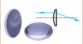
Nearly Constant Focal Length Across a Wide Range of Wavelengths
When using a white light source with a singlet lens, the focal point and circle of least confusion are blurred by chromatic aberration. Chromatic aberration is due to the variation of refractive index with respect to wavelength. In an achromatic doublet this effect is somewhat compensated for by using glasses of two different refractive indexes to cancel these aberrations.
The figures below show the effect on focal length for a number of different wavelengths of light through an achromatic doublet and a plano-convex singlet. The figures also shows how the circle of least confusion for white light is reduced by using an achromatic doublet.
| Damage Threshold Specifications | |
|---|---|
| A-Coated, Cemented Achromatic Doublets | |
| Pulsed | 0.5 J/cm2 (532 nm, 10 ns, 10 Hz, Ø0.566 mm) |
| CWa | 300 W/cm (532 nm, Ø1.000 mm) |
Damage Threshold Data for Thorlabs' A-Coated Achromatic Doublets
The specifications to the right are measured data for Thorlabs' A-coated achromatic doublets. The damage threshold of cemented achromatic doublets is limited by the cement. For applications that require higher damage thresholds, please consider our air-spaced doublets. These specifications are valid for all A-coated, cemented achromatic doublets, regardless of the size or focal length of the lens.
Laser Induced Damage Threshold Tutorial
The following is a general overview of how laser induced damage thresholds are measured and how the values may be utilized in determining the appropriateness of an optic for a given application. When choosing optics, it is important to understand the Laser Induced Damage Threshold (LIDT) of the optics being used. The LIDT for an optic greatly depends on the type of laser you are using. Continuous wave (CW) lasers typically cause damage from thermal effects (absorption either in the coating or in the substrate). Pulsed lasers, on the other hand, often strip electrons from the lattice structure of an optic before causing thermal damage. Note that the guideline presented here assumes room temperature operation and optics in new condition (i.e., within scratch-dig spec, surface free of contamination, etc.). Because dust or other particles on the surface of an optic can cause damage at lower thresholds, we recommend keeping surfaces clean and free of debris. For more information on cleaning optics, please see our Optics Cleaning tutorial.
Testing Method
Thorlabs' LIDT testing is done in compliance with ISO/DIS 11254 and ISO 21254 specifications.
First, a low-power/energy beam is directed to the optic under test. The optic is exposed in 10 locations to this laser beam for 30 seconds (CW) or for a number of pulses (pulse repetition frequency specified). After exposure, the optic is examined by a microscope (~100X magnification) for any visible damage. The number of locations that are damaged at a particular power/energy level is recorded. Next, the power/energy is either increased or decreased and the optic is exposed at 10 new locations. This process is repeated until damage is observed. The damage threshold is then assigned to be the highest power/energy that the optic can withstand without causing damage. A histogram such as that below represents the testing of one BB1-E02 mirror.

The photograph above is a protected aluminum-coated mirror after LIDT testing. In this particular test, it handled 0.43 J/cm2 (1064 nm, 10 ns pulse, 10 Hz, Ø1.000 mm) before damage.

| Example Test Data | |||
|---|---|---|---|
| Fluence | # of Tested Locations | Locations with Damage | Locations Without Damage |
| 1.50 J/cm2 | 10 | 0 | 10 |
| 1.75 J/cm2 | 10 | 0 | 10 |
| 2.00 J/cm2 | 10 | 0 | 10 |
| 2.25 J/cm2 | 10 | 1 | 9 |
| 3.00 J/cm2 | 10 | 1 | 9 |
| 5.00 J/cm2 | 10 | 9 | 1 |
According to the test, the damage threshold of the mirror was 2.00 J/cm2 (532 nm, 10 ns pulse, 10 Hz, Ø0.803 mm). Please keep in mind that these tests are performed on clean optics, as dirt and contamination can significantly lower the damage threshold of a component. While the test results are only representative of one coating run, Thorlabs specifies damage threshold values that account for coating variances.
Continuous Wave and Long-Pulse Lasers
When an optic is damaged by a continuous wave (CW) laser, it is usually due to the melting of the surface as a result of absorbing the laser's energy or damage to the optical coating (antireflection) [1]. Pulsed lasers with pulse lengths longer than 1 µs can be treated as CW lasers for LIDT discussions.
When pulse lengths are between 1 ns and 1 µs, laser-induced damage can occur either because of absorption or a dielectric breakdown (therefore, a user must check both CW and pulsed LIDT). Absorption is either due to an intrinsic property of the optic or due to surface irregularities; thus LIDT values are only valid for optics meeting or exceeding the surface quality specifications given by a manufacturer. While many optics can handle high power CW lasers, cemented (e.g., achromatic doublets) or highly absorptive (e.g., ND filters) optics tend to have lower CW damage thresholds. These lower thresholds are due to absorption or scattering in the cement or metal coating.

LIDT in linear power density vs. pulse length and spot size. For long pulses to CW, linear power density becomes a constant with spot size. This graph was obtained from [1].

Pulsed lasers with high pulse repetition frequencies (PRF) may behave similarly to CW beams. Unfortunately, this is highly dependent on factors such as absorption and thermal diffusivity, so there is no reliable method for determining when a high PRF laser will damage an optic due to thermal effects. For beams with a high PRF both the average and peak powers must be compared to the equivalent CW power. Additionally, for highly transparent materials, there is little to no drop in the LIDT with increasing PRF.
In order to use the specified CW damage threshold of an optic, it is necessary to know the following:
- Wavelength of your laser
- Beam diameter of your beam (1/e2)
- Approximate intensity profile of your beam (e.g., Gaussian)
- Linear power density of your beam (total power divided by 1/e2 beam diameter)
Thorlabs expresses LIDT for CW lasers as a linear power density measured in W/cm. In this regime, the LIDT given as a linear power density can be applied to any beam diameter; one does not need to compute an adjusted LIDT to adjust for changes in spot size, as demonstrated by the graph to the right. Average linear power density can be calculated using the equation below.

The calculation above assumes a uniform beam intensity profile. You must now consider hotspots in the beam or other non-uniform intensity profiles and roughly calculate a maximum power density. For reference, a Gaussian beam typically has a maximum power density that is twice that of the uniform beam (see lower right).
Now compare the maximum power density to that which is specified as the LIDT for the optic. If the optic was tested at a wavelength other than your operating wavelength, the damage threshold must be scaled appropriately. A good rule of thumb is that the damage threshold has a linear relationship with wavelength such that as you move to shorter wavelengths, the damage threshold decreases (i.e., a LIDT of 10 W/cm at 1310 nm scales to 5 W/cm at 655 nm):

While this rule of thumb provides a general trend, it is not a quantitative analysis of LIDT vs wavelength. In CW applications, for instance, damage scales more strongly with absorption in the coating and substrate, which does not necessarily scale well with wavelength. While the above procedure provides a good rule of thumb for LIDT values, please contact Tech Support if your wavelength is different from the specified LIDT wavelength. If your power density is less than the adjusted LIDT of the optic, then the optic should work for your application.
Please note that we have a buffer built in between the specified damage thresholds online and the tests which we have done, which accommodates variation between batches. Upon request, we can provide individual test information and a testing certificate. The damage analysis will be carried out on a similar optic (customer's optic will not be damaged). Testing may result in additional costs or lead times. Contact Tech Support for more information.
Pulsed Lasers
As previously stated, pulsed lasers typically induce a different type of damage to the optic than CW lasers. Pulsed lasers often do not heat the optic enough to damage it; instead, pulsed lasers produce strong electric fields capable of inducing dielectric breakdown in the material. Unfortunately, it can be very difficult to compare the LIDT specification of an optic to your laser. There are multiple regimes in which a pulsed laser can damage an optic and this is based on the laser's pulse length. The highlighted columns in the table below outline the relevant pulse lengths for our specified LIDT values.
Pulses shorter than 10-9 s cannot be compared to our specified LIDT values with much reliability. In this ultra-short-pulse regime various mechanics, such as multiphoton-avalanche ionization, take over as the predominate damage mechanism [2]. In contrast, pulses between 10-7 s and 10-4 s may cause damage to an optic either because of dielectric breakdown or thermal effects. This means that both CW and pulsed damage thresholds must be compared to the laser beam to determine whether the optic is suitable for your application.
| Pulse Duration | t < 10-9 s | 10-9 < t < 10-7 s | 10-7 < t < 10-4 s | t > 10-4 s |
|---|---|---|---|---|
| Damage Mechanism | Avalanche Ionization | Dielectric Breakdown | Dielectric Breakdown or Thermal | Thermal |
| Relevant Damage Specification | No Comparison (See Above) | Pulsed | Pulsed and CW | CW |
When comparing an LIDT specified for a pulsed laser to your laser, it is essential to know the following:

LIDT in energy density vs. pulse length and spot size. For short pulses, energy density becomes a constant with spot size. This graph was obtained from [1].
- Wavelength of your laser
- Energy density of your beam (total energy divided by 1/e2 area)
- Pulse length of your laser
- Pulse repetition frequency (prf) of your laser
- Beam diameter of your laser (1/e2 )
- Approximate intensity profile of your beam (e.g., Gaussian)
The energy density of your beam should be calculated in terms of J/cm2. The graph to the right shows why expressing the LIDT as an energy density provides the best metric for short pulse sources. In this regime, the LIDT given as an energy density can be applied to any beam diameter; one does not need to compute an adjusted LIDT to adjust for changes in spot size. This calculation assumes a uniform beam intensity profile. You must now adjust this energy density to account for hotspots or other nonuniform intensity profiles and roughly calculate a maximum energy density. For reference a Gaussian beam typically has a maximum energy density that is twice that of the 1/e2 beam.
Now compare the maximum energy density to that which is specified as the LIDT for the optic. If the optic was tested at a wavelength other than your operating wavelength, the damage threshold must be scaled appropriately [3]. A good rule of thumb is that the damage threshold has an inverse square root relationship with wavelength such that as you move to shorter wavelengths, the damage threshold decreases (i.e., a LIDT of 1 J/cm2 at 1064 nm scales to 0.7 J/cm2 at 532 nm):

You now have a wavelength-adjusted energy density, which you will use in the following step.
Beam diameter is also important to know when comparing damage thresholds. While the LIDT, when expressed in units of J/cm², scales independently of spot size; large beam sizes are more likely to illuminate a larger number of defects which can lead to greater variances in the LIDT [4]. For data presented here, a <1 mm beam size was used to measure the LIDT. For beams sizes greater than 5 mm, the LIDT (J/cm2) will not scale independently of beam diameter due to the larger size beam exposing more defects.
The pulse length must now be compensated for. The longer the pulse duration, the more energy the optic can handle. For pulse widths between 1 - 100 ns, an approximation is as follows:

Use this formula to calculate the Adjusted LIDT for an optic based on your pulse length. If your maximum energy density is less than this adjusted LIDT maximum energy density, then the optic should be suitable for your application. Keep in mind that this calculation is only used for pulses between 10-9 s and 10-7 s. For pulses between 10-7 s and 10-4 s, the CW LIDT must also be checked before deeming the optic appropriate for your application.
Please note that we have a buffer built in between the specified damage thresholds online and the tests which we have done, which accommodates variation between batches. Upon request, we can provide individual test information and a testing certificate. Contact Tech Support for more information.
[1] R. M. Wood, Optics and Laser Tech. 29, 517 (1998).
[2] Roger M. Wood, Laser-Induced Damage of Optical Materials (Institute of Physics Publishing, Philadelphia, PA, 2003).
[3] C. W. Carr et al., Phys. Rev. Lett. 91, 127402 (2003).
[4] N. Bloembergen, Appl. Opt. 12, 661 (1973).

In order to illustrate the process of determining whether a given laser system will damage an optic, a number of example calculations of laser induced damage threshold are given below. For assistance with performing similar calculations, we provide a spreadsheet calculator that can be downloaded by clicking the button to the right. To use the calculator, enter the specified LIDT value of the optic under consideration and the relevant parameters of your laser system in the green boxes. The spreadsheet will then calculate a linear power density for CW and pulsed systems, as well as an energy density value for pulsed systems. These values are used to calculate adjusted, scaled LIDT values for the optics based on accepted scaling laws. This calculator assumes a Gaussian beam profile, so a correction factor must be introduced for other beam shapes (uniform, etc.). The LIDT scaling laws are determined from empirical relationships; their accuracy is not guaranteed. Remember that absorption by optics or coatings can significantly reduce LIDT in some spectral regions. These LIDT values are not valid for ultrashort pulses less than one nanosecond in duration.
A Gaussian beam profile has about twice the maximum intensity of a uniform beam profile.
CW Laser Example
Suppose that a CW laser system at 1319 nm produces a 0.5 W Gaussian beam that has a 1/e2 diameter of 10 mm. A naive calculation of the average linear power density of this beam would yield a value of 0.5 W/cm, given by the total power divided by the beam diameter:
However, the maximum power density of a Gaussian beam is about twice the maximum power density of a uniform beam, as shown in the graph to the right. Therefore, a more accurate determination of the maximum linear power density of the system is 1 W/cm.
An AC127-030-C achromatic doublet lens has a specified CW LIDT of 350 W/cm, as tested at 1550 nm. CW damage threshold values typically scale directly with the wavelength of the laser source, so this yields an adjusted LIDT value:
The adjusted LIDT value of 350 W/cm x (1319 nm / 1550 nm) = 298 W/cm is significantly higher than the calculated maximum linear power density of the laser system, so it would be safe to use this doublet lens for this application.
Pulsed Nanosecond Laser Example: Scaling for Different Pulse Durations
Suppose that a pulsed Nd:YAG laser system is frequency tripled to produce a 10 Hz output, consisting of 2 ns output pulses at 355 nm, each with 1 J of energy, in a Gaussian beam with a 1.9 cm beam diameter (1/e2). The average energy density of each pulse is found by dividing the pulse energy by the beam area:

As described above, the maximum energy density of a Gaussian beam is about twice the average energy density. So, the maximum energy density of this beam is ~0.7 J/cm2.
The energy density of the beam can be compared to the LIDT values of 1 J/cm2 and 3.5 J/cm2 for a BB1-E01 broadband dielectric mirror and an NB1-K08 Nd:YAG laser line mirror, respectively. Both of these LIDT values, while measured at 355 nm, were determined with a 10 ns pulsed laser at 10 Hz. Therefore, an adjustment must be applied for the shorter pulse duration of the system under consideration. As described on the previous tab, LIDT values in the nanosecond pulse regime scale with the square root of the laser pulse duration:
This adjustment factor results in LIDT values of 0.45 J/cm2 for the BB1-E01 broadband mirror and 1.6 J/cm2 for the Nd:YAG laser line mirror, which are to be compared with the 0.7 J/cm2 maximum energy density of the beam. While the broadband mirror would likely be damaged by the laser, the more specialized laser line mirror is appropriate for use with this system.
Pulsed Nanosecond Laser Example: Scaling for Different Wavelengths
Suppose that a pulsed laser system emits 10 ns pulses at 2.5 Hz, each with 100 mJ of energy at 1064 nm in a 16 mm diameter beam (1/e2) that must be attenuated with a neutral density filter. For a Gaussian output, these specifications result in a maximum energy density of 0.1 J/cm2. The damage threshold of an NDUV10A Ø25 mm, OD 1.0, reflective neutral density filter is 0.05 J/cm2 for 10 ns pulses at 355 nm, while the damage threshold of the similar NE10A absorptive filter is 10 J/cm2 for 10 ns pulses at 532 nm. As described on the previous tab, the LIDT value of an optic scales with the square root of the wavelength in the nanosecond pulse regime:
This scaling gives adjusted LIDT values of 0.08 J/cm2 for the reflective filter and 14 J/cm2 for the absorptive filter. In this case, the absorptive filter is the best choice in order to avoid optical damage.
Pulsed Microsecond Laser Example
Consider a laser system that produces 1 µs pulses, each containing 150 µJ of energy at a repetition rate of 50 kHz, resulting in a relatively high duty cycle of 5%. This system falls somewhere between the regimes of CW and pulsed laser induced damage, and could potentially damage an optic by mechanisms associated with either regime. As a result, both CW and pulsed LIDT values must be compared to the properties of the laser system to ensure safe operation.
If this relatively long-pulse laser emits a Gaussian 12.7 mm diameter beam (1/e2) at 980 nm, then the resulting output has a linear power density of 5.9 W/cm and an energy density of 1.2 x 10⁻⁴ J/cm2 per pulse. This can be compared to the LIDT values for a WPQ10E-980 polymer zero-order quarter-wave plate, which are 5 W/cm for CW radiation at 810 nm and 5 J/cm2 for a 10 ns pulse at 810 nm. As before, the CW LIDT of the optic scales linearly with the laser wavelength, resulting in an adjusted CW value of 6 W/cm at 980 nm. On the other hand, the pulsed LIDT scales with the square root of the laser wavelength and the square root of the pulse duration, resulting in an adjusted value of 55 J/cm2 for a 1 µs pulse at 980 nm. The pulsed LIDT of the optic is significantly greater than the energy density of the laser pulse, so individual pulses will not damage the wave plate. However, the large average linear power density of the laser system may cause thermal damage to the optic, much like a high-power CW beam.
| Posted Comments: | |
Eric Boltersdorf
(posted 2023-08-22 11:16:49.5) Dear Sir or Madam,
do you have values for the transmission between 385nm and 400nm for this product?
Best Regards,
Eric cdolbashian
(posted 2023-08-30 10:13:53.0) Thank you for contacting Thorlabs! We will send the typical data to you via email, please note that slight variations in performance data will occur from lot to lot. Teng Liu
(posted 2023-06-06 15:43:16.057) Hi, I was wondering if you would like to provide an AC508-125-A lens. Currently, my setup needs such a lens. Does it possible to be customer inspired?
Thanks a lot! cdolbashian
(posted 2023-06-12 09:50:17.0) Thank you for reaching out to us with this inquiry. While I do not know if we can make this product at the present time, I have certainly submitted this to our internal product development forum. Perhaps in the future it will indeed be customer inspired. I have additionally contacted you directly to discuss your application. fred couweleers
(posted 2021-09-21 09:41:12.67) why can I no longer order achromat AC508-250-A?
you cannot just without notice change the design of the lens! YLohia
(posted 2021-10-07 08:21:22.0) Thank you for contacting Thorlabs. The 50.8 mm achromatic doublet lenses have been redesigned with an increased thickness. This mitigates issues caused by stress from the adhesive and improves overall performance. We apologize for any inconvenience cause by the redesign. Our OEM team was in touch with your organization last year in January and you were duly notified of the changes. You also received the CAD files for new lenses. We have directly reached out to you with our previous exchanges. Kayoko Fujimura
(posted 2021-08-30 20:55:25.723) AC127-075-Aの外形を□3~4mmの正方形にカットしたいと考えております。
・このようなサイズにカットして頂くことは可能でしょうか。
・加工できる場合、偏心や光軸の傾きはどの程度の大きさ (精度)になるでしょうか。 YLohia
(posted 2021-09-01 10:46:20.0) Hello, an applications engineer from our team in Japan (techsupport.jp@thorlabs.com) will discuss this directly with you. fred couweleers
(posted 2019-04-02 07:25:59.623) is the spherical power tolerance in terms of rings in an interferogram or is is actual deviation (in metres)? YLohia
(posted 2019-04-08 08:38:27.0) Hello, thank you for contacting Thorlabs. The spherical surface power spec is given in terms of the rings in an interferogram. f.delcul
(posted 2019-02-28 15:47:38.837) Hi,
you gave a bad answer. We call a "Doublet" the simplest form of corrected system made of 2 lenses. The maximum achievable system is an aplanatic one with good selection of glasses, so corrected for spherical and coma and also for chromatic aberration. If i follow your mind: it is only an achromatic doublet, i can suggest it is is not corrected for spherical aberration too!. The simple reason for correcting coma in a doublet system is in alignment. An uncorrected coma doublet require a perfect aligment. In a true world it is really difficult to achieve and this is why coma is also corrected. Most of the doublet Thorlabs sell are aplanatic and corrected for coma. This one doesn't respect the rule, to be honest, the simplest fact the rear surface is concave means this doublet was calculated without small amount of field, a mistake in optical calculation!
Best regards
Fabrice Del Cul nbayconich
(posted 2019-03-13 01:54:38.0) Hello again, thank you for bringing this to our attention. We will look into revisiting the designs for these achromats to improve their performance. f.delcul
(posted 2019-02-07 17:28:49.653) Hi Thorlabs crew,
i looked about performance of AC254-200-A doublet and found it is not aplanatic! Shame on you :-). It exhibits strong coma! You need to review optical formula. Best regards. Fabrice Del Cul nbayconich
(posted 2019-02-27 10:08:48.0) Thank you for contacting Thorlabs. My apologies if there was a misunderstanding to these products. These are spherical achromatic doublets and are not designed to have an aspheric surface. I would suggest using the hasting's triplets in order to reduce the amount of coma produced in your application. Please see the link below.
https://www.thorlabs.us/newgrouppage9.cfm?objectgroup_id=5368 cittadinilaser
(posted 2018-10-31 15:48:16.613) Dears Sirs
I have a question about : For best performance, the side of the lens with the largest radius of curvature (flattest side) should face away from the collimated beam. Doublets Ø1/2" and larger are engraved with the part number on the lens so when it is oriented right side up, the flattest side of the lens is the bottom surface. Please see the diagram under the reference drawing link below for additional details.?
In aplication , it seems totally different
Flatttest side is with it´s face to the collimated beam
Please explain the correct position
Thanks in advance
Best Regards
Fernando Cittadini nbayconich
(posted 2018-11-19 02:47:34.0) Thank you for contacting Thorlabs. The flatter side of the lens should always face the focused spot of your beam. The reference drawings on our webpage will indicate the direction of travel your collimated beam should take which should be incident on the most curved surface of the achromatic lens. ethan.cohen
(posted 2017-08-12 00:24:55.46) It would not hurt to widen the transmission curves to show the near IR performance, as this is often used in microscopy. tfrisch
(posted 2017-09-14 11:19:29.0) Hello, thank you for contacting Thorlabs. While I expect variation from one coating run to another, I can send you sample data on the coating reflectivity a bit farther into the IR user
(posted 2016-08-02 11:40:58.313) Do you use NOA61 for cement? If so, the NOA absorbs about 5% of light. Can you share the transmission for each lens? bo.jing
(posted 2016-04-01 16:57:32.013) Would it be possible for you to offer a 1/2", 100mm lens with A coating? I.e. AC127-100-A
Regards besembeson
(posted 2016-04-05 08:50:29.0) Response from Bweh at Thorlabs USA: Yes we can offer this as a special item. I will contact you. MichaelSchwertner
(posted 2015-06-09 09:35:48.663) Dear Thorlabs,
for the Achromats you list the the back focal length on axis. For integration and using CAD, however, it is often useful to also have the BFL value on the edge of the lens. This can be calculated from the BFL on axis and R3 but it would be nice to have this on-edge value of the BFL also in the table. Could you list it please? It would make your website even better.
Thank you and greetings,
Michael besembeson
(posted 2015-09-21 09:10:41.0) Response from Bweh at Thorlabs USA: Thanks for the feedback. We will review this and I will follow up with you with the values for the lenses that are of interest to you. christiaanhulleman
(posted 2014-11-24 17:16:26.52) Is the reflectivity data of the AR coating per lens or per surface? So these lenses would have 2 surfaces each. jlow
(posted 2014-11-25 11:19:04.0) Response from Jeremy at Thorlabs: The reflectivity is per surface. 1039805428
(posted 2014-02-23 15:18:09.86) My fellow bought a lens "AC254-030-A". When I opened the ZEMAX file, it shown 'COATINGTHRO.DAT can't open'. I searched the Zemax install location, I had no this file. Could you send it for me? Thanks very much! jlow
(posted 2014-02-27 02:45:43.0) Response from Jeremy at Thorlabs: We recommend using the .zar files which are a pack and go Zemax zip file which contain both the coating and the lens data. If you cannot use the .zar file format, a simple solution would be to remove the coating from the lens. basili
(posted 2013-10-31 12:14:23.637) It has been shown, in the application page, the spot diameter is 3.6µm for achromatic Doublet and 15µm for Plano-Convex spherical singlet. Both results obtained at 633nm wavelength, φ10mm input beam and 50.0mm focal length. I would like to know formula used in those calculations. jlow
(posted 2013-10-31 03:49:05.0) Response from Jeremy at Thorlabs: The results were obtained using Zemax simulation software. james.parker
(posted 2013-02-07 06:29:34.31) Are you able to provide a CW laser damage threshold for these lenses please? tcohen
(posted 2012-09-27 09:36:00.0) Response from Tim at Thorlabs: We have provided .zar files on the website to allow more information to the user. For users with incompatible versions of Zemax we can provide both individual files and the complete catalog in .zmx format. I will contact you directly to provide this. carlos.macias
(posted 2012-09-25 15:42:58.0) Hi, cant manage to open the *.zar file in my version of zemax. Is there any link to *.zmx files? Many thanks tcohen
(posted 2012-09-18 15:44:00.0) Response from Tim at Thorlabs: These are spherical achromats. Currently we offer air spaced achromats at http://www.thorlabs.com/NewGroupPage9.cfm?ObjectGroup_ID=6083 which have superior performance to cemented versions (see the “Lens Comparison” tab for this data). Furthermore, we are currently working on introducing many new optics which include precision aspherized achromatic lenses. Please contact us at techsupport@thorlabs.com if you would like updates in the process. paul.lauria
(posted 2012-09-14 20:38:47.0) Wondering if these are aspherized as well? Edmund and Newport both have aspherized achromatic doublets, does Thorlabs? Haven't found them if so. regis.sarcia
(posted 2012-07-27 08:07:37.0) Hi, we already use this lens in one of our products and are pretty happy about it. I have to modify the system to measure under 400nm, could you please give me a graph of transmission of the lens between 320nm and 450nm? (no reflection graph please but really the transmission taking into account the absorbance of the lens materials)
thank you in advance
Régis bdada
(posted 2012-01-12 21:14:00.0) Response from Buki at Thorlabs:
You can use solvents like acetone or iso propyl alcohol. Please refer to our optics cleaning guide linked below for more information and contact TechSupport@thorlabs.com if you have any questions.
http://www.thorlabs.com/tutorials.cfm?tabID=26066 luyang
(posted 2012-01-12 17:44:42.0) Can you please let me know how can I clean 1050-1620 achromatic doublet lens with C coating. I found a few finger prints on the lens and I'm afraid of scratch the coating using lens paper. Also can I use solvent to clean without destroying the coating?
Thanks,
Yang bdada
(posted 2011-11-09 10:58:00.0) Response from Buki at Thorlabs:
Thank you for participating in our Feedback Forum. The right material is N-BAF10/N-SF6HT, not N-BAFN10 and N-SFL6HT. We have corrected this typographical error on our website.
Our current doublets are cemented together but we plan to release air spaced achromatic doublets soon, which will not require epoxy. Please contact TechSupport@thorlabs.com if you have further questions. murray.davies
(posted 2011-11-07 17:04:44.0) Can you tell me if the index data your N-BAFN10 and N-SFL6HT is the same as for N-BAF10/N-SF6HT?
Do you make the AC050-008-A1 without using glue? I am doing single photon counting and I am concerned with fluorescence in the glue. jjurado
(posted 2011-04-06 16:05:00.0) Response from Javier at Thorlabs to marco.malinverni: Thank you very much for contacting us. The materials used in this lens are N-BAF10 and SF10, which are highly absorptive below the ~380 nm range. For example, a 10 mm sample of N-BAF10 glass has an internal transmittance of only 17% at 350 nm, and a 10 mm sample of SF10 has a transmittance value of 5.8% at 365 nm. The loss is then mostly attributed to absorption. I will contact you directly for further assistance. marco.malinverni
(posted 2011-04-06 17:57:49.0) How is the absorption of this lens (AC508-100-A1) for wavelengths in the range of 250-300nm? And the focal shift. Thanks. jjurado
(posted 2011-02-08 17:11:00.0) Response from Javier at Thorlabs to bmangum: Thank you very much for contacting us with your request. Although we have not characterized any possible fluorescence effects arising from our achromatic doublets, you are correct in assessing that this behavior is most likely due to the cement used. We are currently working on a new line of air-spaced achromatic doublets which would do away with any fluorescence effects; however, they will not be available for another 4-5 months. I will ocntact you directly to discuss your application a bit further. bmangum
(posted 2011-02-07 19:55:52.0) I am using several focal lengths of these achromats of these lenses with the A coating. I am exciting with several tens of mW of 405 CW laser. I get strong fluorescence coming from the lens. I tested with some other A coated lenses I have and it must be coming from the cement. Have you characterized this before? I really need achromatic lenses for my fluorescence application - but then I am always stuck with the cement issue. Any advice on other products that might work? Thorlabs
(posted 2010-12-06 10:23:32.0) Response from Javier at Thorlabs to hs49: the main tolerance specifications for all of our achromatic lenses are specified on the technical drawing (in pdf format), available under the documents icon ("D) next to each lens part number. For further information, please contact techsupport@thorlabs.com. hs49
(posted 2010-12-03 11:01:07.0) Are there manufacturing tolerance values available for these achromats in terms of surface decenters, tilts, etc.? I need to model their performance in ZEMAX. Thorlabs
(posted 2010-11-08 09:26:30.0) Response from Javier at Thorlabs to Ruelas: We tested some of the links, and they are working properly. I will send you the zmx file for the AC254-250-A shortly. ruelas
(posted 2010-11-05 17:17:37.0) I am trying to obtain the zemax files for 2"OD f=25 cm and 2" OD f=15cm visible achromats. It seems that all the zemax links are broken. jens
(posted 2009-06-19 09:06:42.0) A reply from Jens at Thorlabs: the zemax files can be found under the Documents and Drawings Tab by selecting the corresponding file from column called MFG Spec Thorlabs
(posted 2010-09-17 11:21:00.0) Response from Javier at Thorlabs to carollo:
The damage threshold values we have tested for our achromatic doublet lenses are as follows:
-A coated lenses: 0.5 J/cm^2 (tested at 532nm, 10 ns pulse witdh, 10 Hz rep. rate)
-B coated lenses: 5.0 J/cm^2 (tested at 810 nm, 10 ns pulse witdh, 10 Hz rep. rate)
-C coated lenses: 5.0 J/cm^2 (tested at 1542 nm, 10 ns pulse witdh, 10 Hz rep. rate) carollo
(posted 2010-09-16 17:23:22.0) Hi,
I am interested in using an achromatic lens in a pulsed laser application. Could you please list or send me the specs for the optical damage threshold of the cemented lens?
Thanks,
Ryan Javier
(posted 2010-06-07 21:37:18.0) Response from Javier at Thorlabs to guille2306: We can certainly offer uncoated versions of our MgF2 lenses. We will contact you with details regarding a quotation for these mirrors, reflectivity curves, and we would also be interested in knowing more about your application. guille2306
(posted 2010-06-07 11:54:15.0) Are there uncoated or MgF2 coated versions of this lenses? If yes, do you have reflectivity curves in the 400-1000nm region? jens
(posted 2010-03-29 13:40:57.0) A reply from Jens at Thorlabs to guille2306: we have calculated the reflectivity curve for the visible coating over an extended range. It turns out that the reflectivity will increase to a value of about 8% at 1000nm. I will send you the curve together with data on focal shift information over this range. As initial information the focal lenght will increase by 0.54mm at 1000nm for the AC508-075-A. guille2306
(posted 2010-03-26 17:22:28.0) Hi, I would like to use a single achromatic doublet for the 450-950nm range. Which would be the typical reflectivity of the visible anti-reflection coating in the near infrared (700-1000nm)? And conversely, which would be the typical reflectivity of the near-IR coating in the visible range? jnchacon
(posted 2009-06-18 19:28:58.0) Hi, Im working in the design of a spectrograph and i was thinking to use one of this doublets.
I need the Zemax files in order to evaluate the image quality of the system. Can you tell me where are the zemax file?
Thank.
Juan Chacón (from Chile) technicalmarketing
(posted 2008-01-21 10:12:09.0) As requested, a column has been added to the table in the "Specs" tab that lists a recommended mounting option for each lens. When choosing a lens mount be careful to match the lens diameter and edge thickness specifications to the lens mount. Thank you for the presentation feedback. acable
(posted 2008-01-18 07:20:14.0) Can you add a link from the Specs Tab to the recommended compatible mount within the large table. technicalmarketing
(posted 2008-01-10 14:14:29.0) At this time, our achromatic doublets are not RoHS compliant, and therefore, the type of glass used is SF5 (not N-SF5) and BAFN10 (not N-BAF10). yinnon.glickman
(posted 2008-01-09 04:57:04.0) Hello
Im interested in achromatic doubles. I would like to know the precise type of glass (by Schott catalog) which you refer to as SF5 (is it SF5 or N-SF5?) and BAFN10 (is it N-BAF10?).
Ragards
Yinnon Glickman |
| Item # | Diameter (mm) |
f a (mm) |
fba (mm) |
Graphsb | R1a (mm) |
R2a (mm) |
R3a (mm) |
tc1 (mm) |
tc2 (mm) |
tec (mm) |
Materialsd | Compatible Fixed Lens Mounts |
Reference Drawing |
|---|---|---|---|---|---|---|---|---|---|---|---|---|---|
| AC020-004-A | 2.00 | 4.00 | 2.92 | 2.38 | -2.18 | -7.87 | 1.11 | 1.30 | 2.13 | N-SK16/N-LASF9 | See Footnote e |  |
- Positive values are measured from the right side of the lens as shown in the reference drawing. Negative values are measured from the left side of the lens.
- Click on
 for plots and downloadable data of the focal length shift and transmission for the lens.
 - Edge thicknesses given here are nominal and may vary from optic to optic.
- Substrate materials often have multiple names, which vary depending upon the supplier of the bulk material. The names listed here are the Schott glass types.
- This optic, when secured with epoxy in the LMRA2 adapter, can be mounted into our LMR05(/M) or MLH05(/M) lens mounts, SM05 lens tubes, or 16 mm cage components.
| Item # | Diameter (mm) |
f a (mm) |
fba (mm) |
Graphsb | R1a (mm) |
R2a (mm) |
R3a (mm) |
tc1 (mm) |
tc2 (mm) |
tec (mm) |
Materialsd | Compatible Fixed Lens Mounts |
Reference Drawing |
|---|---|---|---|---|---|---|---|---|---|---|---|---|---|
| AC050-008-A | 5.0 | 7.5 | 5.2 | 5.3 | -3.9 | -17.1 | 2.8 | 1.7 | 3.7 | N-BAF10/N-SF6HT | MLH5(/M) See Footnote e |
|
|
| AC050-010-A | 5.0 | 10.0 | 7.9 | 6.6 | -4.3 | -15.4 | 2.5 | 1.9 | 3.7 | N-BAK4/SF5 | |||
| AC050-015-A | 5.0 | 15.0 | 13.6 | 12.5 | -5.3 | -12.1 | 2.7 | 2.1 | 4.3 | N-BK7/SF2 | See Footnote e |
- Positive values are measured from the right side of the lens as shown in the reference drawing. Negative values are measured from the left side of the lens.
- Click on for plots and downloadable data of the focal length shift and transmission for the lens.
- Edge thicknesses given here are nominal and may vary from optic to optic.
- Substrate materials often have multiple names, which vary depending upon the supplier of the bulk material. The names listed here are the Schott glass types.
- This optic, when secured with epoxy in the LMRA5 adapter, can be mounted into our LMR05(/M) or MLH05(/M) lens mounts, SM05 lens tubes, or 16 mm cage components.
| Item # | Diameter (mm) |
f a (mm) |
fba (mm) |
Graphsb | R1a (mm) |
R2a (mm) |
R3a (mm) |
tc1 (mm) |
tc2 (mm) |
tec (mm) |
Materialsd | Compatible Fixed Lens Mounts |
Reference Drawing |
|---|---|---|---|---|---|---|---|---|---|---|---|---|---|
| AC060-010-A | 6.0 | 10.0 | 7.9 | 6.2 | -4.6 | -19.6 | 2.5 | 1.5 | 3.0 | N-BAK4/SF5 | MLH6(/M) LMR6(/M) See Footnote e |
|
- Positive values are measured from the right side of the lens as shown in the reference drawing. Negative values are measured from the left side of the lens.
- Click on for plots and downloadable data of the focal length shift and transmission for the lens.
- Edge thicknesses given here are nominal and may vary from optic to optic.
- Substrate materials often have multiple names, which vary depending upon the supplier of the bulk material. The names listed here are the Schott glass types.
- This optic, when secured with epoxy in the LMRA6 adapter, can be mounted into our LMR05(/M) or MLH05(/M) lens mounts, SM05 lens tubes, or 16 mm cage components.
| Item # | Diameter (mm) |
f a (mm) |
fba (mm) |
Graphsb | R1a (mm) |
R2a (mm) |
R3a (mm) |
tc1 (mm) |
tc2 (mm) |
tec (mm) |
Materialsd | Compatible Fixed Lens Mounts |
Reference Drawing |
|---|---|---|---|---|---|---|---|---|---|---|---|---|---|
| AC064-013-A | 6.35 | 12.7 | 10.3 | 7.1 | -5.9 | -40.4 | 2.5 | 1.5 | 3.1 | N-BAK4/SF5 | MLH7(/M) LMR7(/M) See Footnote e |
|
|
| AC064-015-A | 6.35 | 15.0 | 13.0 | 8.8 | -6.6 | -21.7 | 2.5 | 1.5 | 3.2 | N-BK7/SF2 |
- Positive values are measured from the right side of the lens as shown in the reference drawing. Negative values are measured from the left side of the lens.
- Click on for plots and downloadable data of the focal length shift and transmission for the lens.
- Edge thicknesses given here are nominal and may vary from optic to optic.
- Substrate materials often have multiple names, which vary depending upon the supplier of the bulk material. The names listed here are the Schott glass types.
- This optic, when secured with epoxy in the LMRA6.35 adapter, can be mounted into our LMR05(/M) or MLH05(/M) lens mounts, SM05 lens tubes, or 16 mm cage components.
| Item # | Diameter (mm) |
f a (mm) |
fba (mm) |
Graphsb | R1a (mm) |
R2a (mm) |
R3a (mm) |
tc1 (mm) |
tc2 (mm) |
tec (mm) |
Materialsd | Compatible Fixed Lens Mounts |
Reference Drawing |
|---|---|---|---|---|---|---|---|---|---|---|---|---|---|
| AC080-010-A | 8.0 | 10.0 | 6.7 | 7.1 | -5.3 | -22.7 | 4.5 | 2.0 | 4.9 | N-BAF10/N-SF6HT | MLH8(/M) See Footnote e |
 |
|
| AC080-016-A | 8.0 | 16.0 | 13.9 | 11.0 | -9.2 | -46.8 | 2.5 | 1.5 | 3.1 | N-BAF10/N-SF6HT | MLH8(/M) LMR8(/M) See Footnote e |
||
| AC080-020-A | 8.0 | 20.0 | 17.8 | 11.1 | -9.2 | -34.8 | 2.5 | 1.5 | 3.0 | N-BK7/SF2 | |||
| AC080-030-A | 8.0 | 30.0 | 27.8 | 16.0 | -13.5 | -59.4 | 2.5 | 1.5 | 3.4 | N-BK7/N-SF2 |
- Positive values are measured from the right side of the lens as shown in the reference drawing. Negative values are measured from the left side of the lens.
- Click on for plots and downloadable data of the focal length shift and transmission for the lens.
- Edge thicknesses given here are nominal and may vary from optic to optic.
- Substrate materials often have multiple names, which vary depending upon the supplier of the bulk material. The names listed here are the Schott glass types.
- This optic, when secured with epoxy in the LMRA8 adapter, can be mounted into our LMR05(/M) or MLH05(/M) lens mounts, SM05 lens tubes, or 16 mm cage components.
| Item # | Diameter (mm) |
f a (mm) |
fba (mm) |
Graphsb | R1a (mm) |
R2a (mm) |
R3a (mm) |
tc1 (mm) |
tc2 (mm) |
tec (mm) |
Materialsd | Compatible Fixed Lens Mounts |
Reference Drawing |
|---|---|---|---|---|---|---|---|---|---|---|---|---|---|
| ACN127-050-A | 12.7 | -50.0 | -52.3 | -25.6 | 25.6 | 372.7 | 1.5 | 2.2 | 4.6 | N-BAK4/SF5 | MLH05(/M) LMR05(/M) LMR05V(/M) LMR05S(/M) |
 |
|
| ACN127-030-A | 12.7 | -30.0 | -32.2 | -16.2 | 16.5 | 154.2 | 1.5 | 2.3 | 5.2 | N-BAK4/SF5 | MLH05(/M) | ||
| ACN127-025-A | 12.7 | -25.0 | -27.0 | -16.9 | 16.5 | 97.7 | 1.5 | 2.5 | 5.4 | N-BAF10/N-SF6HT | See Footnote e | ||
| ACN127-020-A | 12.7 | -20.0 | -22.3 | -13.5 | 14.3 | 87.9 | 1.5 | 3.0 | 6.3 | N-BAF10/N-SF6HT | See Footnote f | ||
| AC127-019-A | 12.7 | 19.0 | 15.7 | 12.9 | -11.0 | -59.3 | 4.5 | 1.5 | 4.0 | N-BAF10/N-SF6HT | MLH05(/M) LMR05(/M) LMR05V(/M) LMR05S(/M) SMR05(/M) |
|
|
| AC127-025-A | 12.7 | 25.0 | 21.5 | 18.8 | -10.6 | -68.1 | 5.0 | 2.0 | 5.6 | N-BAF10/N-SF10 | See Footnote e | ||
| AC127-030-A | 12.7 | 30.0 | 27.5 | 17.9 | -13.5 | -44.2 | 3.5 | 1.5 | 3.4 | N-BK7/SF2 | MLH05(/M) LMR05(/M) LMR05V(/M) LMR05S(/M) SMR05(/M) |
||
| AC127-050-A | 12.7 | 50.0 | 47.2 | 27.4 | -22.5 | -91.8 | 3.5 | 1.5 | 4.0 | N-BK7/SF2 | |||
| AC127-075-A | 12.7 | 75.0 | 72.9 | 41.3 | -34.0 | -137.1 | 2.5 | 1.5 | 3.4 | N-BK7/SF2 |
- Positive values are measured from the right side of the lens as shown in the reference drawing. Negative values are measured from the left side of the lens.
- Click on for plots and downloadable data of the focal length shift and transmission for the lens.
- Edge thicknesses given here are nominal and may vary from optic to optic.
- Substrate materials often have multiple names, which vary depending upon the supplier of the bulk material. The names listed here are the Schott glass types.
- Suggested Fixed Lens Mounts: MLH05(/M) or LMR05(/M) with an SM05L03 Lens Tube
- Suggested Fixed Lens Mounts: MLH05(/M) or LMR05(/M) with an SM05L05 Lens Tube
| Item # | Diameter (mm) |
f a (mm) |
fba (mm) |
Graphsb | R1a (mm) |
R2a (mm) |
R3a (mm) |
tc1 (mm) |
tc2 (mm) |
tec (mm) |
Materialsd | Compatible Fixed Lens Mounts |
Reference Drawing |
|---|---|---|---|---|---|---|---|---|---|---|---|---|---|
| ACN254-100-A | 25.4 | -100.1 | -103.6 | -52.0 | 49.9 | 600.0 | 2.0 | 4.0 | 7.7 | N-BAK4/SF5 | See Foonote e | |
|
| ACN254-075-A | 25.4 | -75.1 | -78.8 | -39.0 | 39.2 | 489.8 | 2.0 | 4.3 | 8.6 | N-BAK4/SF5 | |||
| ACN254-050-A | 25.4 | -50.0 | -53.2 | -34.0 | 32.5 | 189.2 | 2.0 | 4.5 | 9.4 | N-BAF10/N-SF6HT | |||
| ACN254-040-A | 25.4 | -40.1 | -43.6 | -27.1 | 27.1 | 189.2 | 2.0 | 5.0 | 10.6 | N-BAF10/N-SF11 | |||
| AC254-030-A | 25.4 | 30.0 | 22.9 | 20.9 | -16.7 | -79.8 | 12.0 | 2.0 | 8.8 | N-BAF10/N-SF6HT | |
||
| AC254-035-A | 25.4 | 35.2 | 27.3 | 24.0 | -19.1 | -102.1 | 12.0 | 2.0 | 9.6 | N-BAF10/N-SF6HT | |||
| AC254-040-A | 25.4 | 40.1 | 33.4 | 23.7 | -20.1 | -57.7 | 10.0 | 2.5 | 7.4 | N-BK7/SF5 | |||
| AC254-045-A | 25.4 | 45.0 | 40.2 | 31.2 | -25.9 | -130.6 | 7.0 | 2.0 | 5.7 | N-BAF10/N-SF6HT | LMR1(/M) LMR1V(/M) LMR1S(/M) SMR1(/M) |
||
| AC254-050-A | 25.4 | 50.2 | 43.4 | 33.3 | -22.3 | -291.1 | 9.0 | 2.5 | 8.7 | N-BAF10/N-SF10 | See Footnote e | ||
| AC254-060-A | 25.4 | 60.1 | 54.3 | 41.7 | -25.9 | -230.7 | 8.0 | 2.5 | 8.2 | E-BAF11/FD10 | |||
| AC254-075-A | 25.4 | 74.9 | 70.3 | 46.5 | -33.9 | -95.5 | 7.0 | 2.5 | 6.9 | N-BK7/SF5 | LMR1(/M) LMR1V(/M) LMR1S(/M) |
||
| AC254-080-A | 25.4 | 80.0 | 75.3 | 49.6 | -35.5 | -101.2 | 7.0 | 3.0 | 7.3 | N-BK7/N-SF5 | See Footnote e | ||
| AC254-100-A | 25.4 | 100.1 | 97.1 | 62.8 | -45.7 | -128.2 | 4.0 | 2.5 | 4.7 | N-BK7/SF5 | LMR1(/M) LMR1V(/M) LMR1S(/M) SMR1(/M) |
||
| AC254-125-A | 25.4 | 125.0 | 122.0 | 77.6 | -55.9 | -160.8 | 4.0 | 2.8 | 5.0 | N-BK7/N-SF5 | |||
| AC254-150-A | 25.4 | 150.0 | 146.1 | 91.6 | -66.7 | -197.7 | 5.7 | 2.2 | 6.6 | N-BK7/SF5 | LMR1(/M) LMR1V(/M) LMR1S(/M) |
||
| AC254-200-A | 25.4 | 200.2 | 194.0 | 77.4 | -87.6 | 291.1 | 4.0 | 2.5 | 5.7 | N-SSK5/LAFN7 | LMR1(/M) LMR1V(/M) LMR1S(/M) SMR1(/M) |
||
| AC254-250-A | 25.4 | 250.0 | 246.7 | 137.1 | -111.5 | -459.2 | 4.0 | 2.0 | 5.2 | N-BK7/SF2 | |||
| AC254-300-A | 25.4 | 300.2 | 297.0 | 165.2 | -137.1 | -557.4 | 4.0 | 2.0 | 5.4 | N-BK7/SF2 | |||
| AC254-400-A | 25.4 | 399.3 | 396.0 | 219.8 | -181.6 | -738.5 | 4.0 | 2.0 | 5.5 | N-BK7/SF2 | |||
| AC254-500-A | 25.4 | 502.5 | 499.9 | 337.3 | -186.8 | -557.4 | 4.0 | 2.0 | 5.6 | N-BK7/SF2 |
- Positive values are measured from the right side of the lens as shown in the reference drawing. Negative values are measured from the left side of the lens.
- Click on for plots and downloadable data of the focal length shift and transmission for the lens.
- Edge thicknesses given here are nominal and may vary from optic to optic.
- Substrate materials often have multiple names, which vary depending upon the supplier of the bulk material. Most of the materials listed are the Schott glass type with the exception of E-BAF11 (Hikari) and FD10 (Hoya).
- Suggested Fixed Lens Mount: LMR1(/M) with an SM1L05 Lens Tube
| Item # | Diameter (mm) |
f a (mm) |
fba (mm) |
Graphsb | R1a (mm) |
R2a (mm) |
R3a (mm) |
tc1 (mm) |
tc2 (mm) |
tec (mm) |
Materialsd | Compatible Fixed Lens Mounts |
Reference Drawing |
|---|---|---|---|---|---|---|---|---|---|---|---|---|---|
| AC300-050-A | 30.0 | 50.0 | 44.3 | 34.0 | -29.4 | -161.5 | 8.5 | 2.0 | 6.3 | N-BAF10/N-SF6HT | LMR30(/M) | |
|
| AC300-080-A | 30.0 | 80.0 | 74.3 | 56.0 | -44.2 | -219.8 | 8.5 | 2.0 | 7.9 | N-BAF10/N-SF6HT | See Footnote e | ||
| AC300-100-A | 30.0 | 100.0 | 96.4 | 70.0 | -57.0 | -284.4 | 5.0 | 2.0 | 5.0 | N-BAF10/N-SF6HT | LMR30(/M) |
- Positive values are measured from the right side of the lens as shown in the reference drawing. Negative values are measured from the left side of the lens.
- Click on for plots and downloadable data of the focal length shift and transmission for the lens.
- Edge thicknesses given here are nominal and may vary from optic to optic.
- Substrate materials often have multiple names, which vary depending upon the supplier of the bulk material. The names listed here are the Schott glass types.
- Suggested Fixed Lens Mount: LMR30(/M) with an SM30L05 Lens Tube
| Item # | Diameter (mm) |
f a (mm) |
fba (mm) |
Graphsb | R1a (mm) |
R2a (mm) |
R3a (mm) |
tc1 (mm) |
tc2 (mm) |
tec (mm) |
Materialsd | Compatible Fixed Lens Mounts |
Reference Drawing |
|---|---|---|---|---|---|---|---|---|---|---|---|---|---|
| AC508-075-A | 50.8 | 74.9 | 61.8 | 50.8 | -41.7 | -247.7 | 20.0 | 3.0 | 14.9 | E-BAF11/N-SF11 | See Footnote e | |
|
| AC508-080-A | 50.8 | 80.0 | 69.9 | 54.9 | -46.4 | -247.2 | 16.0 | 2.0 | 10.5 | N-BAF10/N-SF6HT | |||
| AC508-100-A | 50.8 | 100.0 | 89.0 | 71.1 | -44.2 | -363.1 | 16.0 | 4.0 | 14.4 | N-BAF10/N-SF10 | |||
| AC508-150-A | 50.8 | 150.0 | 140.4 | 83.2 | -72.1 | -247.7 | 12.0 | 3.0 | 9.7 | N-BK7/SF5 | See Footnote f | ||
| AC508-180-Ag | 50.8 | 180.0 | 172.7 | 109.7 | -80.7 | -238.5 | 12.0 | 2.0 | 9.4 | N-BK7/N-SF5 | |||
| ACT508-200-Ag | 50.8 | 200.0 | 190.6 | 106.2 | -92.1 | -409.4 | 10.6 | 6.0 | 12.8 | N-BK7/N-SF2 | See Footnote e | ||
| ACT508-250-A | 50.8 | 250.0 | 241.4 | 131.2 | -116.0 | -538.1 | 9.3 | 6.0 | 12.3 | N-BK7/N-SF2 | |||
| ACT508-300-A | 50.8 | 300.0 | 291.3 | 153.7 | -139.9 | -706.8 | 8.4 | 7.0 | 12.4 | N-BK7/N-SF2 | |||
| ACT508-400-A | 50.8 | 400.0 | 394.6 | 292.3 | -148.9 | -398.5 | 8.0 | 8.0 | 14.1 | N-BK7/N-SF2 | |||
| ACT508-500-A | 50.8 | 500.0 | 496.3 | 382.5 | -182.1 | -471.2 | 6.0 | 6.0 | 10.5 | N-BK7/N-SF2 | |||
| ACT508-750-A | 50.8 | 750.0 | 743.9 | 398.6 | -343.7 | -1544.5 | 6.0 | 6.0 | 11.0 | N-BK7/N-SF2 | |||
| ACT508-1000-A | 50.8 | 1000.0 | 996.4 | 757.9 | -364.7 | -954.2 | 6.0 | 6.0 | 11.3 | N-BK7/N-SF2 |
- Positive values are measured from the right side of the lens as shown in the reference drawing. Negative values are measured from the left side of the lens.
- Click on for plots and downloadable data of the focal length shift and transmission for the lens.
- Edge thicknesses given here are nominal and may vary from optic to optic.
- Substrate materials often have multiple names, which vary depending upon the supplier of the bulk material. Most of the materials listed are the Schott glass type with the exception of E-BAF11 (Hikari).
- Suggested Fixed Lens Mount: LMR2(/M) with SM2L10 Lens Tube
- Suggested Fixed Lens Mount: LMR2(/M) with SM2L05 Lens Tube
- Common microscope tube lens focal lengths. We also offer an infinity corrected tube lens with f = 200 mm here.