 Products Home / Actuators, Adjusters, & Transducers / Piezoelectric Actuators / Piezoelectric/Screw Actuators
Piezoelectric/Screw Actuators
- Manual Coarse Adjustment with Piezoelectric Fine Adjustment
- Easy Integration into Translation Stages or Mirror Mounts
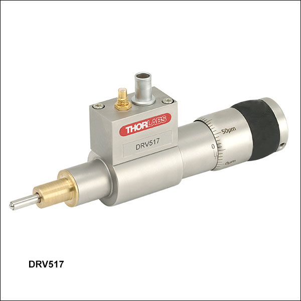
DRV517
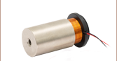
PE4
POLARIS-P20
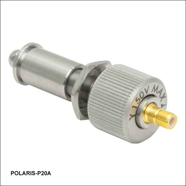
POLARIS-P20A


Please Wait
These piezo-assisted actuators contain a piezo stack mounted in series with the leadscrew.
PE4
The PE4 actuator provides 4 mm of manual coarse travel via a 0.010" pitch leadscrew. The 150 V internal piezo stack provides 15 μm of open-loop piezo travel. The actuator is equipped with a Ø9.5 mm (Ø3/8") mounting barrel.
POLARIS-P20
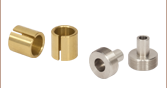
This actuator with a Ø0.50" stainless steel bushing, used in our Ø1" and Ø2" Polaris® Mirror Mounts with Piezoelectric Adjusters, provides 0.375" of travel with at least 15.4 µm of fine piezo adjustment. The actuator includes a stainless steel bushing for installation in a mirror mount or other optomechanical setup. One adjuster lock nut is included; the lock nut can hold the manual adjustment in place without affecting the piezoelectric fine adjustment.
POLARIS-P20A
This actuator with a Ø0.349" stainless steel bushing, used in our Ø1/2" Polaris® Mirror Mount with Piezoelectric Adjusters, provides 0.375" of travel with at least 17.0 µm of fine piezo adjustment. The actuator includes a stainless steel bushing for installation in a mirror mount or other optomechanical setup. One adjuster lock nut is included; the lock nut can hold the manual adjustment in place without affecting the piezoelectric fine adjustment.
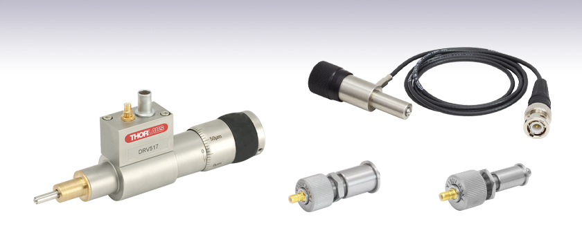
DRV517
The DRV517 actuator is equipped with a Ø9.5 mm (Ø3/8") mounting barrel and has an in-line piezo and a manual micrometer with 1/2" of travel. This micrometer has clearly marked graduations every 5 μm while the main body is engraved with graduations every 1 mm. The included strain gauge is capable of providing positional feedback over the 30 μm of piezo travel with 10 nm of resolution. A PAA622 piezo control cable is also included.
| Item # | PE4 | POLARIS-P20 | POLARIS-P20A | DRV517 |
|---|---|---|---|---|
| Manual Travel Range | 4 mm | 0.375" (9.53 mm) | 0.375" (9.53 mm) | 0.50" (12.7 mm) |
| Manual Resolution | 1 μma | 0.26 mm/rev | 0.26 mm/rev | 1 μma |
| Piezo Travel Range | 15 μm | 15.4 µm (Min) 19.4 µm (Max) |
17.0 µm (Min) 21.0 µm (Max) |
30 μm |
| Piezo Resolution | 10 nmb | 0.017 µm for a 0.1 V Stepc | 0.013 µm for a 0.1 V Stepd | 10 nma |
| Piezo Driving Voltage | 150 V | 0 to 150 V | 0 to 150 V | 75 V |
| Piezo Capacitance | 0.35 µF | 0.35 µF | 7.2 µF | |
| Mounting Barrel | Ø9.5 mm (Ø3/8") | Ø0.50" (Ø12.7 mm) | Ø0.349" (Ø8.86 mm) | Ø9.5 mm (Ø3/8") |
| Screw Threading | - | 3/8"-100 | 1/4"-100 | - |
| Vacuum Compatibility | - | 10-9 Torr at 25 °C with Proper Bake Out 10-5 Torr at 25 °C without Bake Out Grease Vapor Pressure: 10-13 Torr at 20 °C, 10-5 Torr at 200 °C; Epoxy Meets Low Outgassing Standards NASA ASTM E595 and Telcordia GR-1221 |
- | |
PE4 Piezo Connection
BNC Male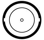
0 - 150 V
POLARIS-P20 and POLARIS-P20A
Piezo Connection

0 - 150 V
DRV517 Connections
Displacement Sensor
7 Pin LEMO Male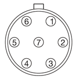
| Displacement Sensor Pin Designations | |
|---|---|
| 1 | +15 V for Instrumentation Amplfier and Operational Amplifier |
| 2 | + Oscillator Signal, Bridge Drive Sine Wave at 18 kHz (Nominal) When Used with KSG101 K-Cube™ Strain Gauge Reader, 4 V Peak-to-Peak |
| 3 | 0 V Ground Reference |
| 4 | 0 V Ground Reference |
| 5 | + AC Signal Out, Proportional to Deflection, 18 kHz, 2 V Peak-to-Peak |
| 6 | -15 V for Instrumentation Amplifier and Operational Amplifier |
| 7 | 2 kΩ Resistor, Identifies the Distance Travelled When Used with KSG101 K-Cube™ Strain Gauge Reader |
Piezo Drive Input
Maximum Input Voltage: 75 V
Piezo Driver Bandwidth Tutorial
Knowing the rate at which a piezo is capable of changing lengths is essential in many high-speed applications. The bandwidth of a piezo controller and stack can be estimated if the following is known:
- The maximum amount of current the controllers can produce. This is 0.5 A for our BPC Series Piezo Controllers, which is the driver used in the examples below.
- The load capacitance of the piezo. The higher the capacitance, the slower the system.
- The desired signal amplitude (V), which determines the length that the piezo extends.
- The absolute maximum bandwidth of the driver, which is independent of the load being driven.
To drive the output capacitor, current is needed to charge it and to discharge it. The change in charge, dV/dt, is called the slew rate. The larger the capacitance, the more current needed:
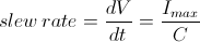
For example, if a 100 µm stack with a capacitance of 20 µF is being driven by a BPC Series piezo controller with a maximum current of 0.5 A, the slew rate is given by
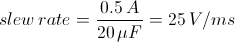
Hence, for an instantaneous voltage change from 0 V to 75 V, it would take 3 ms for the output voltage to reach 75 V.
Note: For these calculations, it is assumed that the absolute maximum bandwidth of the driver is much higher than the bandwidths calculated, and thus, driver bandwidth is not a limiting factor. Also please note that these calculations only apply for open-loop systems. In closed-loop mode, the slow response of the feedback loop puts another limit on the bandwidth.
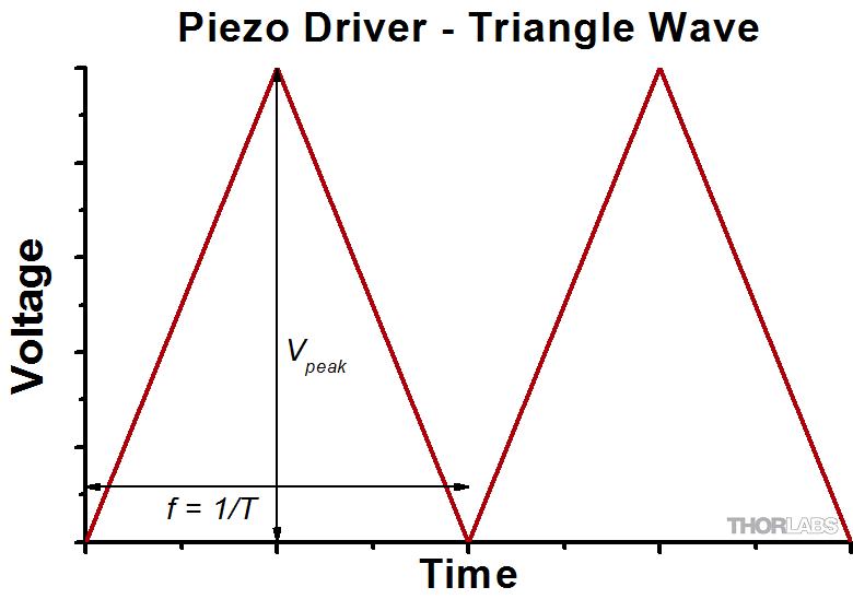
Sinusoidal Signal
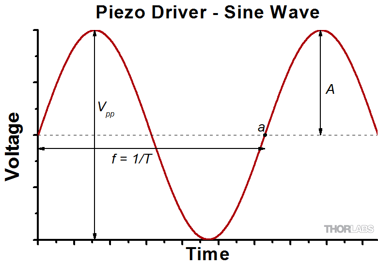
The bandwidth of the system usually refers to the system's response to a sinusoidal signal of a given amplitude. For a piezo element driven by a sinusoidal signal of peak amplitude A, peak-to-peak voltage Vpp, and frequency f, we have:
A diagram of voltage as a function of time is shown to the right. The maximum slew rate, or voltage change, is reached at t = 2nπ, (n=0, 1, 2,...) at point a in the diagram to the right:
From the first equation, above:

Thus,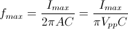
For the example above, the maximum full-range (75 V) bandwidth would be
 .
.
For a smaller piezo stack with 10 times lower capacitance, the results would be 10 times better, or about 1060 Hz. Or, if the peak-to-peak signal is reduced to 7.5 V (10% max amplitude) with the 100 µm stack, again, the result would be 10 times better at about 1060 Hz.
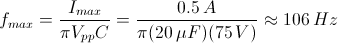
Triangle Wave Signal
For a piezo actuator driven by a triangle wave of max voltage Vpeak and minimum voltage of 0, the slew rate is equal to the slope:
![]() .
.
Or, since f = 1/T:
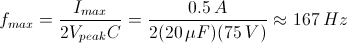
Square Wave Signal
For a piezo actuator driven by a square wave of maximum voltage Vpeak and minimum voltage 0, the slew rate limits the minimum rise and fall times. In this case, the slew rate is equal to the slope while the signal is rising or falling. If tr is the minimum rise time, then
or
 .
.
For additional information about piezo theory and operation, see the Piezoelectric Tutorials page.
| Posted Comments: | |
Michael Chase
(posted 2023-09-01 08:44:31.29) I plan to use the Polaris-P20 with a custom mount. Can you provide the holding force and push force so I can properly size the springs and preload? Also, are these self locking at rest? If I align my system and remove power, what happens? jdelia
(posted 2023-09-20 02:58:53.0) Thank you for contacting Thorlabs. I have reached out to you directly to discuss the requirements of your application. If you align your system and remove power, they will retract under the spring preload and park. You would have to design a break into your system if you want them to remain in place when the power is removed. As is, they will perform similar to piezo-actuated self-aligning and adjusting automotive headlights and drop down and park when the lights are turned off and then rise and realign when the lights are turned on. Typically, a feedback loop is designed into the system to provide for a zero-drift mount or a vibration-canceling mount for instance. user
(posted 2023-08-22 09:50:27.937) Hi, we were using a DRV517 when it suddenly made a grinding noise and then stopped, are there any known issues that may have caused this? fguzman
(posted 2023-08-23 09:57:16.0) Thanks for enquiry. We will contact you directly to further troubleshoot this issue. Donghyuk Ko
(posted 2022-05-09 01:20:06.203) Dear Thorlabs,
I'm using Thorlabs Polaris Piezo actuated mirror mounts in the lab.
However, the pieozo travel length of Polaris-P20 is not long enough to compensate my laser beam movement.
Can you modify your Polaris-P20 piezo/screw actuator as a longer piezo/screw actuator like Polaris-P40 to cover 40um travel length?
If you can, I'd like to buy your modified Polaris-P40 piezo/screw actuators for my Polaris mirror mounts.
I'm waiting for your answer.
Thank you very much.
Best regards,
Donghyuk Ko jdelia
(posted 2022-05-13 02:10:17.0) Thank you for contacting Thorlabs. We have contacted you directly to discuss your application and the feasibility of this custom request. Steffen Böhme
(posted 2021-07-07 03:10:52.68) Please can you tell me about the following feature about the
"POLARIS-P20 - Piezoelectric Actuator with Stainless Steel Bushing, 3/8" Manual Travel, ≥15.4 µm Piezo Travel"
Does this piezoelectric actuator using a self-looking mechanism or need it a permanent voltage to hold the adjusted position?
Thank you in advance.
Best regards,
Steffen Boehme YLohia
(posted 2021-07-07 02:58:08.0) One adjuster lock nut is included; the lock nut can hold the manual adjustment in place without affecting the piezoelectric fine adjustment. Stefan Persijn
(posted 2020-09-24 10:06:29.18) Using these actuators for >10 years. Some observations:
-grease comes out after some time from the tip side.
-grease becomes 'hard' after some time as a result this the manual travel doesn't work anymore. Opening the actuator and cleaning it can resolve this
-they stop working after typically 1-4 years of use (using Thorlabs piezo driver) (kind of short-circuit)
-Price is somewhat high considering the limited lifetime llamb
(posted 2020-10-09 01:26:59.0) Hello Stefan, thank you for contacting Thorlabs. We appreciate your feedback on the PE4 piezo actuator, and it has been logged with our engineering team. We will certainly look into its design for ways to improve it. user
(posted 2019-06-28 21:05:32.733) What is the maximum axial load capacity of DRV517? AManickavasagam
(posted 2019-07-01 11:23:20.0) Response from Arunthathi at Thorlabs: Thanks for your query. Unfortunately, we do not have a spec for the Axial load capacity of the actuator. However, I have contacted you directly to get further details on the load and stage you intend to use with the actuator which would help to determine the feasibility for your setup. Paul D
(posted 2019-06-26 07:15:13.22) Hello,
Is it possible to use the Polaris P-20 to resonate at 3kHz with a 10 µm travel into a polaris kinematic mirror mount? In other words, is the piezo going to withstand the cyclic mechanical load?
Thanks llamb
(posted 2019-07-01 04:39:01.0) Hello, thank you for contacting Thorlabs. I have reached out to you directly to get more details about the specific mount and optic you intend to use the POLARIS-P20 with, as the load will impact the resonance. We are also looking to test the POLARIS-P20 bandwidth for failure and will follow up with you with the test results once completed. joe.bath
(posted 2018-05-10 10:32:35.207) Hi
Please can you tell me what the exact length of the PZT itself in the PE4 is, and its layer thickness? YLohia
(posted 2018-05-14 08:30:06.0) Hello, thank you for contacting Thorlabs. The PE4 contains the AE0505D16F piezo, the length of which is 20.0 mm and layer thickness is 100 um. joe.bath
(posted 2018-05-10 10:28:45.563) Hi
I need to know what the layer thickness is in the PE4
Thank you user
(posted 2016-12-08 10:09:16.76) Can you verify that the center pin is positive for the piezo voltage? bwood
(posted 2016-12-09 04:30:08.0) Response from Ben at Thorlabs: Thank you for your feedback. In general, our piezo devices use a positive voltage input, so the central pin will be positive on the BNC or SMC inputs of these actuators. adam
(posted 2016-02-09 15:32:55.087) hello, it is possible to mount PE4 actuator into SM1Z translation stage? Thanks besembeson
(posted 2016-02-11 09:34:39.0) Response from Bweh at Thorlabs USA: We don't have a suitable adapter for such mounting at this time. Please contact me at techsupport@thorlabs.com to discuss your application further and explore other options. g.laliberte
(posted 2015-09-01 15:28:30.68) Hi,
Sorry to ask again, but we bought a drv517, and I'd really like to have the descritpion of the feedback circuit of the piezo actuator. How can I use that strain gauge if I don't know how it's wired?? besembeson
(posted 2015-09-29 01:32:16.0) Response from Bweh at Thorlabs USA: We provide the pin diagram and description at the following link, under the "Pin Diagram" tab: http://www.thorlabs.com/NewGroupPage9.cfm?ObjectGroup_ID=1076. You can contact me at techsupport@thorlabs.com with further questions. g.laliberte
(posted 2015-08-27 21:19:12.71) We bought the dr517 piezo actuator, but there is no information about the internal position sensing strain gage. The table on your website shows:
Pin Designation
1 +15 V
2 Oscillator +
3 0 V
4 Signal Out -
5 Signal Out +
6 -15 V
7 Travel
But what is the meaning of those signals? We want to build our own readout circuit (resistance bridge?)
Best regards
Gabriel Laliberte
Physics technician bwood
(posted 2015-09-02 04:34:44.0) Response from Ben at Thorlabs: Thank you for your feedback. We are always happy to provide additional details on our products, and we will be contacting you directly with an explanation of the pins with supporting documents. roman.slaby
(posted 2015-07-07 10:01:28.707) Hallo, I would like to ask for value of Feed force or Holding force. Thank you very much, Roman rcapehorn
(posted 2015-07-07 08:24:53.0) Response from Rob at Thorlabs: Thank you for your feedback. The Max Load force of the piezo used within the DRV517 is 2000N. Please contact us at techsupport.uk@thorlabs.com if you require any further information. bdada
(posted 2011-06-09 17:41:00.0) Response from Buki at Thorlabs:
Thank you for your feedback. Factors that can affect the piezo resolution are the noise from the driver and the voltage precision of the driver. However, the 10nm resolution we specify for the PE4 is due to the limitations of the position sensing detector that we used to measure the resolution. Therefore, the specified 10nm is limited by the resolution of our measuring device.
Please contact TechSupport@thorlabs.com if you have more questions. simon.holzberger
(posted 2011-06-07 10:28:17.0) What actually limits the resolution of the piezoelectric actuator in an open-loop setup to the 10nm? Is it only the noise of the power supply, or are there in the case of the PE4 other limitations? jjurado
(posted 2011-05-26 09:49:00.0) Response from Javier at Thorlabs to last poster: Thank you very much for your feedback. Most applications involving piezo electric actuators assume a positive driving voltage, given that the piezo crystals are almost always poled for positive voltage input during the manufacturing process. Regarding the driving voltage value, we have added this information to the specs chart on the Overview tab. Please contact us at techsupport@thorlabs.com if you have any further questions. user
(posted 2011-05-25 17:08:08.0) Information about the required drive voltage and polarity appears to be lacking. A few more details in the description would be useful. bdada
(posted 2011-04-25 17:32:00.0) Response from Buki at Thorlabs:
When the knob of the PE4 actuator is turned, the actuator pin moves. The actuator pin has the ball attached. Please contact TechSupport@thorlabs.com if you have further questions. user
(posted 2011-04-24 22:18:29.0) Not clear from the dwg what part moves. Would be good to have a dwg showing the part fully extended and fully contracted. Laurie
(posted 2009-03-10 15:28:30.0) Response from Laurie at Thorlabs to rausch: Our specifications tabs provide most of the technical data regarding the PE4 piezo actuator and the NF5DP20 piezo translation stage. This tab can be accessed under the family image at the top of the page. If you cannot find the technical data you are seeking under this tab, please let us know. rausch
(posted 2009-03-09 12:18:25.0) Hello,
for our application we are interested in the following items:
PE4 piezo actuator &
NF5DP20 piezo translation stage
It is possible to obtain more information / technical data regarding the piezos and overall system resonance frequencies, their modulation capacity and driving voltages?
Thank you very much,
Stefan |

 Zoom
Zoom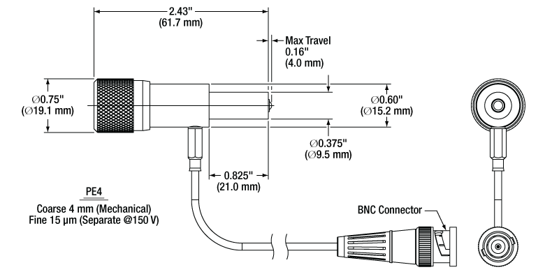
Click to Enlarge
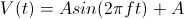
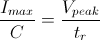
PE4 Mechanical Drawing
- 4 mm Manual Coarse Adjustment
- 15 µm Piezoelectric Fine Adjustment
- Ø3/8" (9.5 mm) Mounting Barrel
- BNC Cable Attached
The PE4 actuator is a manual adjuster with 4 mm of manual travel, while an integrated piezoelectric element provides 15 µm of fine adjustment. It can be mounted by the Ø3/8" mounting barrel. A BNC cable is attached to the body of the actuator.
We recommend driving this piezo actuator with the KPZ101, MDT693B, or MDT694B piezo controllers.

 Zoom
Zoom
Click for Details
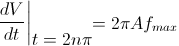
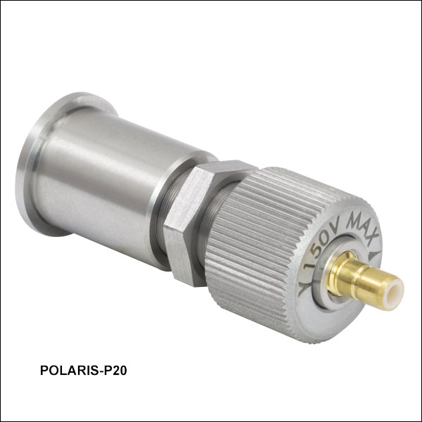
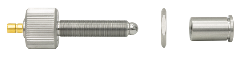
POLARIS-P20 Mechanical Drawing
- Manual Coarse Adjustment Range: 0.375"
- Piezoelectric Fine Adjustment Range: 15.4 µm (Min)
- 3/8"-100 Adjuster Mounted in Ø0.50" Stainless Steel Bushing
- Male SMB Connector (Cable Not Included)
Click to Enlarge
Piezoelectric Actuator Shown Removed from Lock Nut and Bushing
The POLARIS-P20 piezoelectric actuator provides up to 0.375" of manual adjustment with a 3/8"-100 screw and piezo-controlled fine adjustment with a maximum travel range between 15.4 and 19.4 µm. It includes a Ø0.50" stainless steel bushing and 12 mm lock nut, which can be tightened or loosened by hand or with a 12 mm thin-head, open-ended hex wrench. Holding the adjuster in place with the lock nut will not affect the piezoelectric adjustment.
The adjuster screw, lock nut, and bushing are machined from stainless steel, which has a low coefficient of thermal expansion (CTE) for stability in environments with large temperature fluctuations. When mounting the bushing into a machined bore, using components fabricated from the same material is recommended. Ensure the actuator is removed from the bushing before oven-curing the glue.
The adjuster screw is the same as that included in our Ø1" and Ø2" Polaris Mirror Mounts with Piezoelectric Adjusters and can be used as a replacement adjuster.
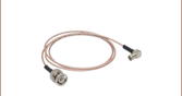
The piezo actuator features a male SMB connector; an SMB-to-BNC cable is not included. We offer the PAA236R cable with a 90° SMB connector on one end and a straight BNC connector on the other. We recommend driving this piezo actuator with the MDT693B, MDT694B, or KPZ101 piezo controller. The MDT693B and MTD394B controllers can be connected directly to the POLARIS-P20 actuator using the PAA236R SMB-to-BNC cable. The KPZ101 K-Cube™ Piezo Controller uses a male SMC connector for the voltage output, requiring additional adapters or cables to connect to the actuator.
Note: The POLARIS-P20 actuator has 3/8"-100 threads and is not compatible with the POLARIS-K05P2 mount, which incorporates 1/4"-100 adjuster screws. This actuator includes a 12 mm 3/8"-100 locking nut, which can be removed in order to install a POLARIS-LN4 locking nut. By using this 13 mm locking nut, users may take advantage of the TW13 preset torque wrench.

 Zoom
Zoom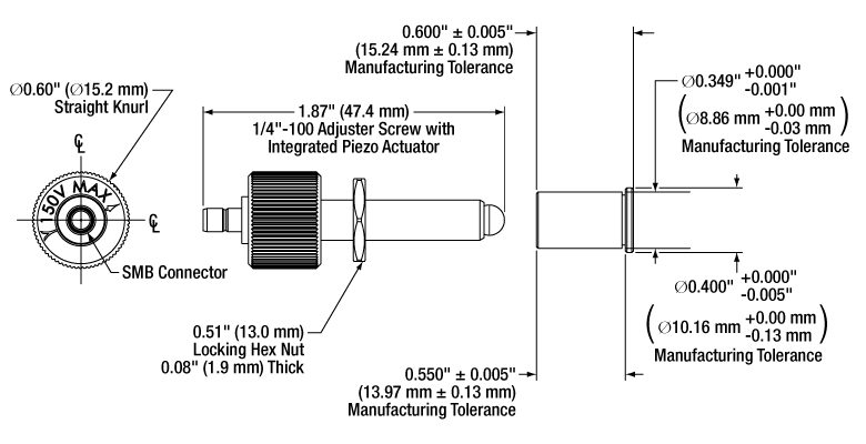
Click for Details
POLARIS-P20A Mechanical Drawing
- Manual Coarse Adjustment Range: 0.375"
- Piezoelectric Fine Adjustment Range: 17.0 µm (Min)
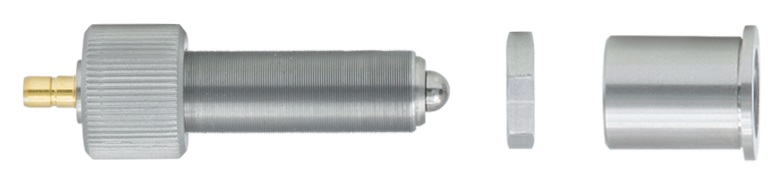
- 1/4"-100 Adjuster Mounted in Ø0.349" Stainless Steel Bushing
- Male SMB Connector (Cable Not Included)
Click to Enlarge
POLARIS-P20A Piezoelectric Actuator Shown Removed from Lock Nut and Bushing
The POLARIS-P20A Piezoelectric Actuator provides up to 0.375" of manual adjustment with a 1/4"-100 screw and piezo-controlled fine adjustment with a maximum travel range between 17.0 and 21.0 µm. It includes a Ø0.349" stainless steel bushing and POLARIS-LN1 13 mm Hex Lock Nut, which can be tightened or loosened by hand or with a TW13 Preset Torque Wrench. Holding the adjuster in place with the lock nut will not affect the piezoelectric adjustment.
The adjuster screw, lock nut, and bushing are machined from stainless steel, which has a low coefficient of thermal expansion (CTE) for stability in environments with large temperature fluctuations. When mounting the bushing into a machined bore, using components fabricated from the same material is recommended. Ensure the actuator is removed from the bushing before oven-curing the glue.
The adjuster screw is the same as that included in our POLARIS-K05P2 Polaris Piezoelectric Ø1/2" Mirror Mount and can be used as a replacement adjuster. If using the POLARIS-P20A adjuster for this application, we recommend using the 11 mm hex lock nut included with the POLARIS-K05P2 mount, as the 13 mm hex lock nut included with the POLARIS-P20A will extend beyond the outer edge of the mount.
The piezo actuator features a male SMB connector; an SMB-to-BNC cable is not included. We offer the PAA236R cable with a 90° SMB connector on one end and a straight BNC connector on the other. We recommend driving this piezo actuator with the MDT693B, MDT694B, or KPZ101 piezo controller. The MDT693B and MTD394B controllers can be connected directly to the POLARIS-P20A actuator using the PAA236R SMB-to-BNC cable. The KPZ101 K-Cube™ Piezo Controller uses a male SMC connector for the voltage output, requiring additional adapters or cables to connect to the actuator.
Note: The POLARIS-P20A actuator has 1/4"-100 threads and is not compatible with our Ø1" and Ø2" Polaris Mirror Mounts with Piezoelectric Adjusters, which incorporate 3/8"-100 adjuster screws.

 Zoom
Zoom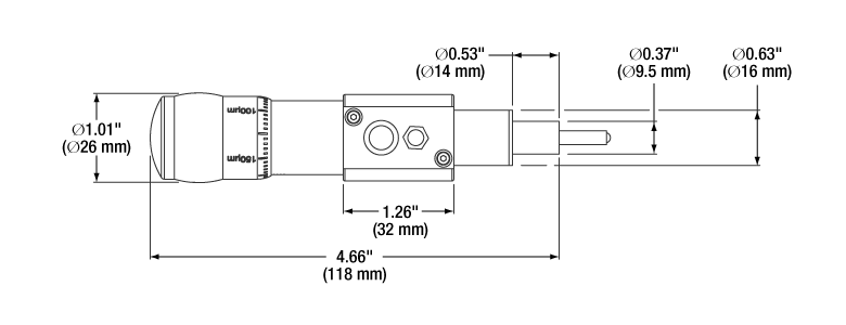
Click to Enlarge
DRV517 Mechanical Drawing
- 12.7 mm Manual Coarse Adjustment
- 30 µm Piezoelectric Fine Adjustment
- Ø3/8" (9.5 mm) Mounting Barrel
- Graduated Tick Marks for Every 5 µm of Travel
- Piezoelectric Feedback Converter Cable Included
The DRV517 is a differential micrometer with an integrated piezoelectric element. The manual adjuster is a capable of up to 1/2" of travel. The adjuster knob features graduated tick marks for every 5 µm of travel, while the main body has tick marks at every 1 mm. The piezo element is equipped with a strain gauge that is capable of providing positional feedback over the 30 μm of piezo travel with 10 nm of resolution. A PAA622 piezo control cable is also included.
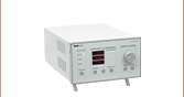
This piezo actuator can be driven by the KPZ101 K-Cube™ 150 V Piezo Controller with a KSG101 K-Cube Strain Gauge Reader for closed-loop operation. The BPC301 or BPC303 USB Closed-Loop Piezo Controllers also provide closed-loop operation.