 Products Home / Drivers & Mounts / OEM Laser Diode & TEC Systems / IC Laser Diode Controllers in SMT Packages
IC Laser Diode Controllers in SMT Packages
- Compact, Highly Integrated Laser Diode Drivers
- 14-Pin SMT Package Enables Quick Automated Assembly
- Designed for OEM, Custom, and Embedded Systems
- Volume Pricing Available
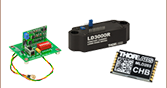
MLD203CHB
Constant Current & High Bandwidth
MLD203CLN
Constant Current & Low Noise
MLDEVAL
Evaluation Board
MLD203P1
Constant Power for Pin Codes A, B, and F
MLD203P2
Constant Power for Pin Codes C and D
17.0 mm
10.0 mm
56.0 mm
100.0 mm


Please Wait
| Feature Comparisona | ||||
|---|---|---|---|---|
| Item # | MLD203CHB | MLD203CLN | MLD203P1 | MLD203P2 |
| Key Features | Constant Current & High Bandwidth | Constant Current & Low Noise | Constant Power | Constant Power |
| Current Noise (RMS) |
12 µA | 3 µA | 3 µA | 3 µA |
| Modulation Bandwidth (3 dB) |
DC to 100 kHz | DC to 1 kHz | N/A | N/A |
| Laser Pin Codes (Click for Diagram) |
All (A through H) | All (A through H) | A, B, and F | C and D |
| Data Sheet (Click for PDF) | ||||

Volume Pricing and OEM Support
Thorlabs' production facilities are capable of manufacturing laser diode controllers in high volumes, and we pass the savings associated with planned production on to our customers. To learn more, please contact our OEM team. An OEM specialist will contact you within 24 hours or the next business day.
Features
- Maximum of 200 mA Operating Current at 3 V Compliance Voltage
- Optical Output Power can be Set by External Voltage, Fixed Resistor, or Variable Resistor
- Soft Start and Brownout Protection to Protect Laser from Current Transients
- Compact 17.0 mm × 10.0 mm × 2.8 mm Package Aids System Integration
- Evaluation Board Available for Test Applications
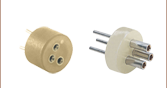
- Ideal for Small Assemblies that Use TO Can Laser Diodes, Diode Sockets, and Aspheric Lenses
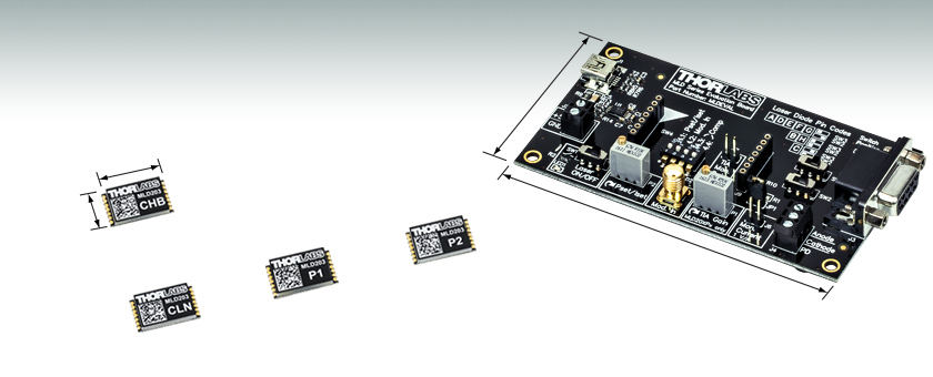
These OEM-grade laser diode drivers are surface-mount devices (SMDs) that provide stable, low-noise drive current. They support a maximum operating current of 200 mA, a maximum compliance voltage of 3 V, and modulation bandwidths up to 100 kHz (see the table to the right). Each driver is contained within a 14-pin surface-mount technology (SMT) package that uses a 5 V supply voltage for operation. The compact 17.0 mm × 10.0 mm × 2.8 mm form factor uses plated half-hole connectors to allow easy surface mounting and electrical connections.
Our highly integrated drivers include soft start and brownout protection features that prevent fast, unexpected current transients from being sent to the laser diode. The operating setpoint of the driver is controlled by an applied voltage, allowing the laser's optical output power to be fixed at the time of assembly (via an external resistor) or adjustable (via an external control voltage or a variable resistor). Independent reference voltage outputs are included for the driver and the laser diode.
These drivers are offered in constant current and constant power models. The Feature Comparison table to the right summarizes the key differences between each model. Complete specifications are available in the Specs tab.
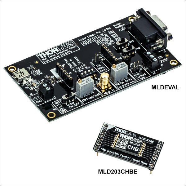
Evaluation Board
For customers interested in testing the performance characteristics of our drivers, we offer an evaluation board. This board contains a female DB9 connector and a screw terminal for laser diode connections, trimpots for selecting the operating setpoint of the driver, and a female SMA connector for modulation signals. Power is supplied via USB or an external 5 VDC source. Each of our drivers is available pre-mounted on a daughterboard that converts the 14-pin SMT layout of the driver to the mating sockets on the evaluation board.
Evaluation Board
| Item # | MLDEVAL |
|---|---|
| Supply Voltage | 5 VDC ± 5% |
| Operating Temperature | 0 °C to +40 °C |
| Storage Temperature | -40 °C to +70 °C |
| Dimensions | 105.8 mm × 56.0 mm × 14.1 mm |
| Weight | 40 g |
Absolute Maximum Ratings (All Drivers)
| Absolute Maximum Ratings | |
|---|---|
| Supply Voltage | 6 V |
| Power Dissipation | 750 mW |
| Operating Temperature | -25 °C to +90 °C |
| Storage Temperature | -40 °C to +100 °C |
Constant Current LD Drivers
| Item # | MLD203CHB(E) | MLD203CLN(E) | Notes |
|---|---|---|---|
| Operating Mode |
Constant Current | - | |
| Laser Pin Codes |
All (A through H) | See Diagram Below | |
| Supply Voltage | 4.5 V to 5.5 V | - | |
| Laser Current | |||
| Current Range | 0 mA to 200 mA | - | |
| Compliance Voltage | 3.0 V (Max) | For 5 V Supply Voltage | |
| Accuracy | ±(2% + 1 mA) [Typical] | Full Scale; After 10 Minute Warm-Up | |
| Repeatability | ±0.1% | Full Scale | |
| Noise | 12 µA (RMS) | 3 µA (RMS) | 10 Hz to 10 MHz; Measured with a 10 Ω Resistor |
| Drift | 20 µA | 30 Minutes, 0 to 10 Hz, Tamb = 25 °C | |
| Temperature Coefficient | 100 ppm/°C | - | |
| Laser Current Setpoint and Modulation | |||
| Input Impedance | 1 MΩ | - | |
| Input Voltage Range | 0 V to 2.5 V | - | |
| Input Voltage Offset | 90 mV (Typical) | - | |
| Modulation Bandwidth | DC to 100 kHz | DC to 1 kHz | 3 dB; Measured with a 10 Ω Resistor |
| Modulation Coefficient | 80 mA/V ± 5% | - | |
| Laser Current Reference Output | |||
| Laser Current Coefficient |
1 mV/mA | For 1 Ω Resistor in Series | |
| Measurement Accuracy | 1% | For ≥10 kΩ Load | |
| Physical Data | |||
| Operating Temperature | -20 °C to +70 °C | Non-Condensing | |
| Storage Temperature |
-40 °C to +100 °C | Non-Condensing | |
| Warm-Up Time for Rated Accuracy |
10 Minutes | - | |
| Dimensions of SMT Package |
17.0 mm × 10.0 mm × 2.8 mm | - | |
| Dimensions of Daughterboard with SMT Package | 38.0 mm × 19.0 mm × 12.9 mm | MLD203CHBE and MLD203CLNE Only | |
| Weight | 1.0 g | - | |
Constant Power LD Drivers
| Item # | MLD203P1(E) | MLD203P2(E) | Notes |
|---|---|---|---|
| Operating Mode |
Constant Power | - | |
| Laser Pin Codes |
A, B, and F | C and D | See Diagram Below |
| Supply Voltage | 4.5 V to 5.5 V | - | |
| Laser Current | |||
| Current Range | 0 mA to 200 mA | - | |
| Compliance Voltage | 3.0 V (Max) | For 5 V Supply Voltage | |
| Noise | 3 µA (RMS) | 10 Hz to 10 MHz Measured with 10 Ω Resistor in Series with L635P5 Laser Diode (for MLD203P1) or with L637P5 Laser Diode (for MLD203P2) |
|
| Laser Power Control | |||
| Current Range of Monitor Photodiode |
2 µA to 2 mA | - | |
| Accuracy | ±2% (Typical) | Full Scale; After 10 Minute Warm-Up | |
| Repeatability | ±0.1% | Full Scale | |
| Drift | 20 nA | 24 Hours, Tamb = 25 °C Measured at P = 4.5 mW with L635P5 Laser Diode (for MLD203P1) or with L637P5 Laser Diode (for MLD203P2) |
|
| Temperature Coefficient | 55 ppm/°C | - | |
| Laser Current Setpoint | |||
| Input Impedance | 1 MΩ | - | |
| Input Voltage Range | 0 V to 2.5 V | - | |
| Voltage Conversion Coefficient Range | 8 µA/V to 800 µA/V ± 5% | Adjustable | |
| Laser Current Reference Output | |||
| Laser Current Coefficient | 1 mV/mA | For 1 Ω Resistor in Series | |
| Measurement Accuracy | 1% | For ≥10 kΩ Load | |
| Physical Data | |||
| Operating Temperature | -20 °C to +70 °C | Non-Condensing | |
| Storage Temperature |
-40 °C to +100 °C | Non-Condensing | |
| Warm-Up Time for Rated Accuracy |
10 Minutes | - | |
| Dimensions of SMT Package |
17.0 mm × 10.0 mm × 2.8 mm | - | |
| Dimensions of Daughterboard with SMT Package | 38.0 mm × 19.0 mm × 12.9 mm | MLD203P1E and MLD203P2E Only | |
| Weight | 1.0 g | - | |
Laser Diode Pin Codes
All pin codes (A through H) are compatible with constant current operation. Pin codes A, B, C, D, and F
include monitor photodiodes, and are therefore also compatible with constant power operation.
Laser Diode Drivers
Pin Layout
These pin assignments correspond to viewing the driver from the top when the engraving on the driver is right-side up.
Land Pattern Data
| MLD203CHB & MLD203CLN Constant Current Drivers | ||
|---|---|---|
| Pin | Name | Description |
| 1 | VIN1 | Supply Voltage Input 1 |
| 2 | VIN2 | Supply Voltage Input 2 |
| 3 | GND1 | Supply Voltage Ground |
| 4 | GND2 | Return Pin (Ground) for Pin 6 |
| 5 | VREFOUT | Reference Output Voltage (+2.5 V) |
| 6 | ISET | Input Voltage for Current Setpoint |
| IMOD | Input Modulation Voltage | |
| 7 | NC | No Connection |
| 8 | NC | No Connection |
| 9 | NC | No Connection |
| 10 | NC | No Connection |
| 11 | LDC | Laser Diode Cathode |
| 12 | ISENS+ | Reference Output Voltage for Laser Diode Current |
| 13 | ISENS- | |
| 14 | LDA | Laser Diode Anode |
| MLD203P1 Constant Power Driver | ||
|---|---|---|
| Pin | Name | Description |
| 1 | VIN1 | Supply Voltage Input 1 |
| 2 | VIN2 | Supply Voltage Input 2 |
| 3 | GND1 | Supply Voltage Ground |
| 4 | GND2 | Return Pin (Ground) for Pin 6 |
| 5 | VREFOUT | Reference Output Voltage (+2.5 V) |
| 6 | PSET | Input Voltage for Power Setpoint |
| 7 | NC | No Connection |
| 8 | PDA | Photodiode Anode |
| 9 | COMP2 | Feedback Resistor; Used to Set Gain of Voltage-to-Voltage Amplifier (See Chapter 3 of the Data Sheet) |
| 10 | COMP1 | |
| 11 | GND_LD | Laser Diode Ground (Cathode) |
| 12 | ISENS+ | Reference Output Voltage for Laser Diode Current |
| 13 | ISENS- | |
| 14 | LDA | Laser Diode Anode |
| MLD203P2 Constant Power Driver | ||
|---|---|---|
| Pin | Name | Description |
| 1 | VIN1 | Supply Voltage Input 1 |
| 2 | VIN2 | Supply Voltage Input 2 |
| 3 | GND1 | Supply Voltage Ground |
| 4 | GND2 | Return Pin (Ground) for Pin 6 |
| 5 | VREFOUT | Reference Output Voltage (+2.5 V) |
| 6 | PSET | Input Voltage for Power Setpoint |
| 7 | NC | No Connection |
| 8 | PDC | Photodiode Cathode |
| 9 | COMP2 | Feedback Resistor; Used to Set Gain of Voltage-to-Voltage Amplifier (See Chapter 3 of the Data Sheet) |
| 10 | COMP1 | |
| 11 | GND_LD | Laser Diode Ground (Cathode) |
| 12 | ISENS+ | Reference Output Voltage for Laser Diode Current |
| 13 | ISENS- | |
| 14 | LDA | Laser Diode Anode |
MLDEVAL Evaluation Board
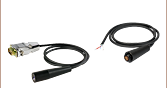
Strain Relief Cable Connector
Female DB9 Connector
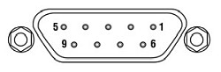
| DB9 Pina | Laser Pin Code (Click for Diagram) | |||||||
|---|---|---|---|---|---|---|---|---|
| A | B | C | D | E | F | G | H | |
| 1 | No Connection | |||||||
| 2 | - | - | PD Cathode | PD Cathode | - | - | - | - |
| 3 | LD Anode | LD Cathode | LD Cathode | LD Anode | LD Anode | LD Anode | LD Anode | LD Cathode |
| 4 | PD Anode | PD Anode | - | - | - | PD Anode | - | - |
| 5 | No Connection | |||||||
| 6 | No Connection | |||||||
| 7 | LD Cathode | - | - | LD Cathode | LD Cathode | LD Cathode | LD Cathode | - |
| 8 | - | LD Anode | LD Anode | - | - | - | - | LD Anode |
| 9 | No Connection | |||||||
Modulation Input
Female SMA Connector
Input Voltage: 0 - 2.5 V
Input Impedance: 1 MΩ
| Posted Comments: | |
ChaeWon Kim
(posted 2023-12-01 14:15:32.7) Hello. I wonder if the MLDEVAL board and L980P010 diode are compatible. When I look at the website, it says they are compatible, but when I look at the board, I can't see the part where I can plug in the diode. Can I purchase and use another adapter in this case? Or can I just plug it in and use the laser? I'll wait for the answer. thank you. dpossin
(posted 2023-12-06 05:09:30.0) Dear Chae Won Kim,
Thank you for your inquiry. The MLDEVAL board alone is not feasible to drive laser diodes. You additionally need an suitable laser mount. For the L980P010 for example, the LDM56/M would work. I´ll reach out to you to discuss your application in more detail. user
(posted 2022-07-18 12:30:55.417) Are the formulas for the relation between laser diode current and setpoint control voltage correct on the page 8 in Data sheets of Laser Drivers MLD203CLN and MLD203CHB?
If setpoint control voltage is +2.5V, laser diode current would be 0.0002A (200uA ). dpossin
(posted 2022-07-19 04:45:13.0) Dear customer,
Thank you for your feedback. Yes you are right. The formula there is not entirely correct. Instead of 12500 ohms it should read 12.5 ohms of internal resistance. We try to correct this typo in the future. Sorry for the inconvenience! Peter Johnston
(posted 2022-04-14 13:37:38.027) The MLD203 datasheet is incorrect for the set current formula. It should be I_LD = V_SET/12.5, not 12500! Please update! mdiekmann
(posted 2022-04-22 02:47:31.0) Thank you very much for your feedback! We are looking into an update of the manual. Tony Pugatschew
(posted 2022-03-28 20:42:13.233) Dear Sir/
Modulation requirement at 2 Htz.
Data sheet does not specify the method?
Modulate Voltage rail ??
Any info apprecated.
Thanks
Tony Pugatschew dpossin
(posted 2022-04-01 09:23:32.0) Dear Tony,
Thank you for your feedback. I am reaching out to you in order to provide information how to correctly set up the MLD203CHB. Manuel B.
(posted 2020-09-23 22:05:28.4) The drivers works really great but the compliance voltage is really low. Is there any way to increase the voltage up to 5V by changing VIN2 or adding an offset voltage source? I want to use these drivers with the L405P20, PL450B and possibly L520P50, which all consume less than 200mA but the operating voltage is larger than 3V. Thanks nreusch
(posted 2020-09-25 06:27:38.0) Thank you for your feedback. The current models of our MLD series are not designed to provide up to 5 V. As there have been several inquiries from customers for higher compliance voltage MLDs, we will evaluate internally whether we would be able to offer such drivers in the future. They will, however, not be available on short time scales. I will contact you directly to check your requirements and time schedule in detail. In the meanwhile, you could probably use one of the other OEM or benchtop drivers like IP250-BV or LDC202C. 寛之 遠藤
(posted 2019-10-10 16:24:06.81) 現在、MLDEVALを用いてLDを駆動させようとしておりますが、LD出力が非常に急峻に変化してしまい、正常に動作させることができません。
こちらの製品について、正常に動作させるための技術的なサポートを受けることは可能でしょうか。ご回答をお待ちしております。 wskopalik
(posted 2019-10-10 05:29:21.0) This is a response from Wolfgang at Thorlabs. Thank you for your inquiry!
We will contact you regarding your issues with the MLDEVAL. Jan Soukup
(posted 2019-04-09 17:23:00.687) How can I drive a green laser diode that needs a 5.4 to 7 Volts operating voltage from MLDEVAL with MLD203P1E.
Thanks Jan swick
(posted 2019-04-18 04:18:19.0) This is a response from Sebastian at Thorlabs. Thank you for the inquiry. The MLD203P1E is designed for driving light sources in constant-power mode by regulating electrical current so that optical output power stays stable. The signal to which the driver regulates to needs to be generated by an optical sensor. An other point is that MLD203P1E works up to 200 mA and 3V which is is not suitable for LEDs with 5.4 to 7 V. I contacted you directly to provide further assistance. seungbum-yang
(posted 2018-10-18 23:54:32.023) I am using MLDEVAL evaluation board with MLD203P1.
most of the time it is OK. but sometimes, It feels like the laser is fluctuating periodically. the period is usually in few second scale, mostly about 4 sec.
I have checked this through checking correlation from laser speckle image.
Is there any reason that you know of regarding the laser fluctuation in period? swick
(posted 2018-11-02 04:52:49.0) This is a response from Sebastian at Thorlabs. Thank you for the inquiry.
The issue you are reporting sound like a drift which might be related to a non-stable temperature of the laserdiode.
This effect could be based on many parts within the setup.
I contacted you directly for troubleshooting. dreader
(posted 2018-06-07 08:46:48.657) Hi, the comments in your feedback section suggest that some customization may be possible to achieve a higher compliance voltage. If so, can you tell me more about it? mvonsivers
(posted 2018-06-12 06:30:40.0) This is a response from Moritz at Thorlabs. Thank you for your inquiry and the interest in our products. I will contact you directly to discuss our options for customization. eileenscannelll
(posted 2018-05-27 21:26:54.873) Query re diode laser removal systems mvonsivers
(posted 2018-06-01 04:13:58.0) This is a response from Moritz at Thorlabs. Thank you for your inquiry. I will contact you directly to further discuss your application. chaowenliang
(posted 2017-10-16 03:45:53.0) The MLD 3V compliance Voltage is too low for the Blue and UV diode. If you can raise it up to 8v, what's the maximum current available? swick
(posted 2017-10-20 03:49:33.0) This is a response from Sebastian at Thorlabs. Thank you for the inquiry. We do not offer MLDs with compliance voltage of 8V. Alternatively you can use LDC202C, LDC205C or LDC210C which have compliance voltage of 10V. ludoangot
(posted 2017-04-18 16:32:11.083) Would it be possible you consider making such a driver with the same efficient design and ease of use but with higher maximum current and compliance voltage? swick
(posted 2017-04-19 03:11:04.0) This is a response from Sebastian at Thorlabs. Thank you for the feedback. We can modify our MLD modules for custom applications with different current and voltages ranges.
I will contact you directly to discuss further details. ludoangot
(posted 2016-09-23 12:14:49.8) Hello, can the drivers be used in a parallel configuration to increase the output current? And how does the circuit behaves when the compliance voltage is reached and exceeded? swick
(posted 2016-09-27 10:14:16.0) This is a response from Sebastian at Thorlabs. Thank you very much for your questions. The Constant Current Laser Drivers (MLD203CLN and MLD203CHB) can be paralleled to increase output current.
For optimal load sharing an additional load resistor can be added.
When the compliance voltage is exceeded the maximum output current will decrease. cbrideau
(posted 2016-09-14 16:33:47.54) What enclosure does the MLDEVAL fit in? swick
(posted 2016-09-15 05:41:39.0) This is a response from Sebastian at Thorlabs. Thank you very much for your feedback.
We have developed this evaluation board to offer a multifunctional tool to test products of our MLD Series before a PCB has to be designed for integrating our modules into specific applications.
Therefore the MLDEVAL is made for evaluation purposes. It provides rubber feet to ensure stable stand on a laboratory table without the need of extra housing.
For OEM customers we can offer customized application boards, which fits perfectly to customized housings. mitch
(posted 2016-08-28 07:02:00.877) Hi, this new product look extremely useful - thanks! I would like to use the constant power version with my own custom bias-T for analog modulation. Is this device compatible if I were to connect a bias-t (perhaps your one) between the LD and the GND_LD or LDA pin? I prefer to use type A laser diodes. Thanks swick
(posted 2016-08-29 04:32:32.0) This is a response from Sebastian at Thorlabs. Thank you very much for your inquiry.
Using a Bias-T with our Constant Power LD Driver (MLD203P1) will not work, because it would disturb the internal regulation of the output power. Modulation of MLD203P1 can be done by modulating P-Set(input) with approx. 1-50 kHz.
With our Constant Current Drivers (MLD203CHB and MLD203CLN) it will work to use a Bias-T for modulation.
I will contact you directly to discuss your application in more detail. ludoangot
(posted 2016-08-25 12:00:59.203) Is there any limitation to using these to drive LED (providing the LED complies with the driver's specs)? Also, I totally second the previous comment. A blank or pre-soldered PCB for fast prototyping with these drivers would be very welcome. Ideally with the option to plug said PCB into common breadboards (0.1 in pitch). swick
(posted 2016-08-25 03:11:58.0) This is a response from Sebastian at Thorlabs. Thank you very much for your inquiry.
It will work to drive LEDs with MLD203CHB or MLD203CLN if all important parameters of the LEDs are due to the controller's specification. Most limiting factor for driving LEDs with MLDCxx modules will be the compliance voltage, which is typical 3 V.
Regarding the PCB for fast prototyping, we will release an evaluation board during next weeks. Together with the evaluation board we will release the requested adapter plug with 0.1 in pitch pin headers for direct use in breadboards. cbrideau
(posted 2016-08-17 14:14:42.88) A version of these pre-soldered on a break-out PCB with protoboard tinned holes sized to fit into one of the EEB enclosures would be very helpful for DIY assembly. swick
(posted 2016-08-18 08:42:45.0) This is a response from Sebastian at Thorlabs. Thank you very much for your feedback. We will look into this, discuss your suggestion internally and contact you directly by email. |

 Zoom
Zoom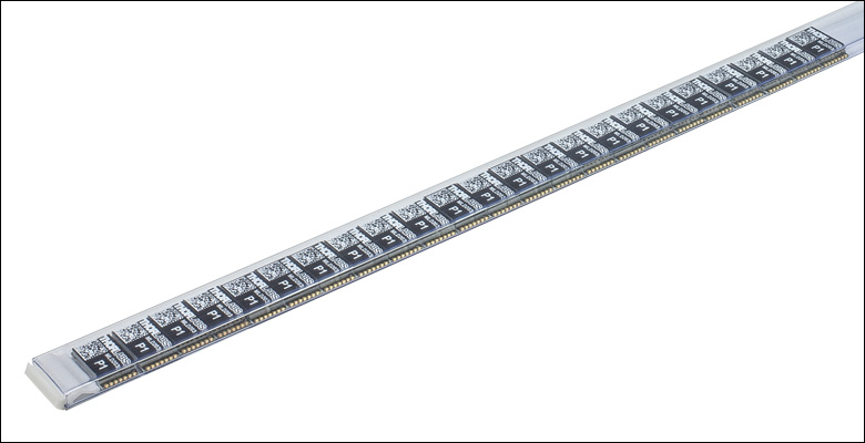
Click for Details
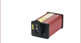
Upon request, large-quantity orders of our drivers can be delivered in an IC tube for simplified integration with assembly equipment.
- Constant Current LD Drivers for All Pin Codes (A through H)
- MLD203CHB: Optimized for High Modulation Bandwidth (Up to 100 kHz at 3 dB)
- MLD203CLN: Optimized for Low Current Noise (3 µA RMS)
- Constant Power LD Drivers
- MLD203P1: For Pin Codes A, B, and F
- MLD203P2: For Pin Codes C and D
Volume pricing is available for these laser diode drivers. To view our current price schedules, please click the "Volume Pricing" links located below.
Drivers compatible with the sockets on the MLDEVAL Evaluation Board are sold separately below.
Laser Diode Pin Codes

 Zoom
Zoom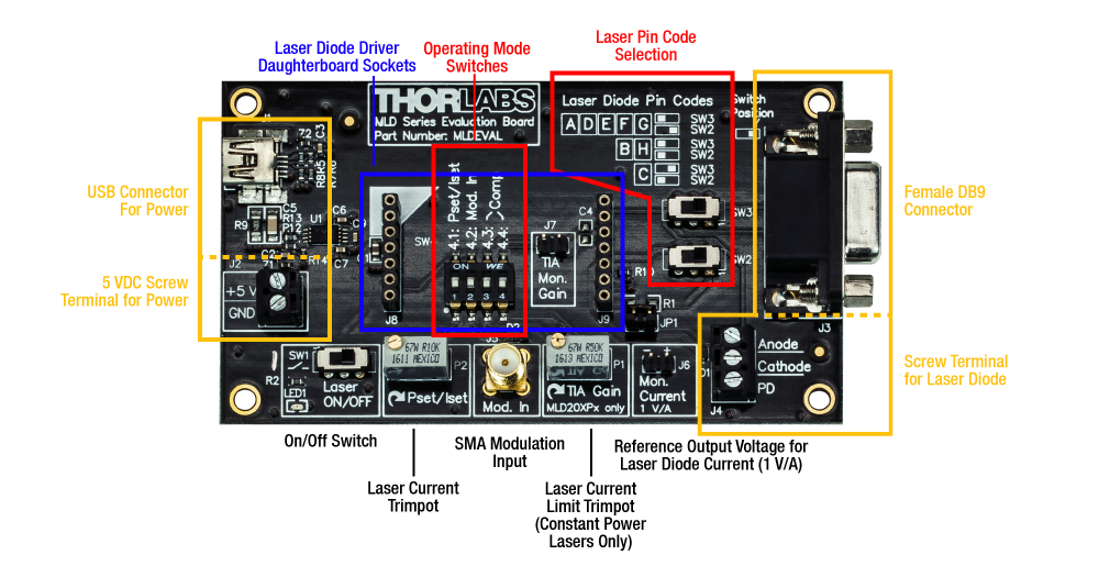
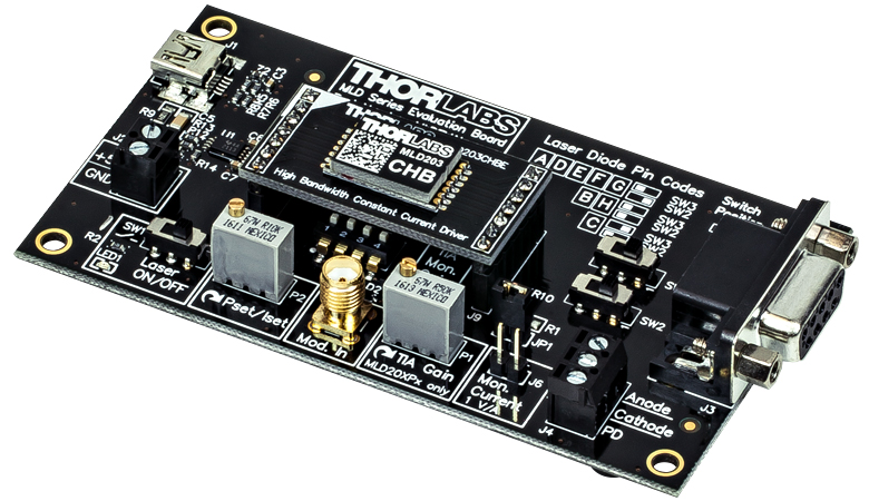
Click to Enlarge
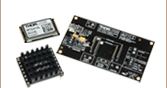
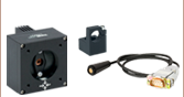
Evaluation Board with MLD203CHBE Driver Installed
- Evaluation Board for Test Applications with OEM Laser Diode Drivers
- Female DB9 Connector and Screw Terminal for a Laser Diode
- USB Connector and Screw Terminal for 5 VDC Power
- Trimpots Control Operating Setpoint of Laser Diode
- SMA Connector for Modulation Signal Input
- Laser Diode Drivers Designed to Mount onto Evaluation Board
Evaluation Board
The MLDEVAL Evaluation Board is a break-out board that interfaces our OEM-grade laser diode drivers with several common connectors. It includes a female DB9 connector that accepts laser diodes connected to a strain relief cable, as well as a screw terminal which the user may wire directly to a TO can laser diode. Power can be supplied either via USB or through a screw terminal that accepts a 5 VDC power supply.
Two trimpots control the operating setpoint of the laser diode. The Pset/Iset trimpot tunes the laser current from 0 mA to 200 mA and is used with both constant current and constant power drivers. The TIA Gain trimpot sets the limit of the monitor diode's current and is therefore only used with constant power drivers. To allow remote modulation of the laser's optical output power, a female SMA connector accepts an applied voltage (see the Specs tab for operating parameters).
The board's overall dimensions are 105.8 mm × 56.0 mm × 14.1 mm, including the female DB9 connector. Four Ø3.2 mm through holes are located at the corners for use in custom mounting.
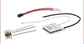
Laser Diode Drivers for use with Evaluation Board
Our OEM-grade laser diode drivers contain plated half-hole connectors that are intended for installation by automated assembly systems. For ease of installation with the MLDEVAL evaluation board, each driver is available pre-mounted on a daughterboard. This daughterboard is installed by inserting it into mating sockets on the evaluation board, allowing these drivers to be quickly deployed in laboratory and test environments.
Prior to installing the driver, several switches on the evaluation board will need to be set to the correct positions, depending upon the selected driver and the pin code of the laser. The correct positions are detailed in chapters 4 and 5 of the evaluation board's manual. Some of these switches are not to be changed once the driver is chosen, and are hence not accessible while the driver is installed.