 Products Home
Wollaston Prisms
- Two Orthogonally Polarized Outputs with a 1°, 1° 20', or 20° Separation Angle
- High Extinction Ratio
- AR-Coated Versions Available
- Available in Calcite, MgF2, Quartz, α-BBO, or YVO4
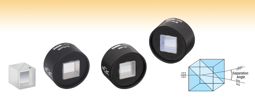
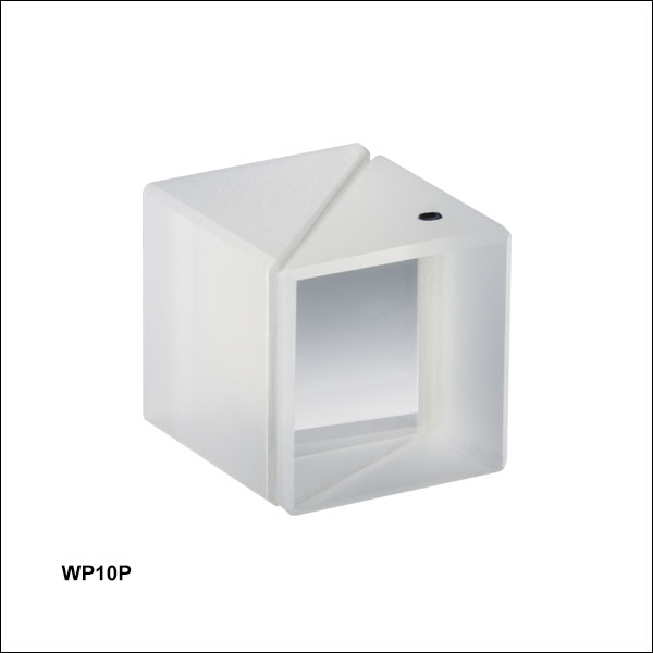
WP10P
Unmounted Calcite
Wollaston Prism
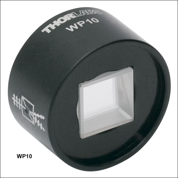
WP10
Mounted Calcite Wollaston Prism
WP10-B
Mounted, AR-Coated Calcite Wollaston Prism
1°, 1° 20', or 20° Separation Angle
WPQ10
Mounted Quartz Wollaston Prism


Please Wait
Features
- Separates Unpolarized Light into Two Orthogonally Polarized Outputs with a Small (1° or 1° 20') or Large (20°) Separation Angle
- High Extinction Ratio in Each Output
- Quartz and MgF2: >10 000:1
- α-BBO, YVO4, and Calcite: >100 000:1
- Prisms Available in Quartz, Magnesium Fluoride, α-BBO, or Calcite Substrates
- Calcite Prisms AR-Coated for 350 - 700 nm or 650 - 1050 nm
- Ø10 mm Clear Aperture
- Available Mounted in Ø1" Housing or Unmounted
Thorlabs' Wollaston Prisms split unpolarized incident light into two orthogonally polarized outputs. The quartz, calcite, and YVO4 Wollaston prisms sold here are made of two prisms cemented together. In contrast, our magnesium fluoride and α-BBO Wollaston prisms are made of two prisms that are optically contacted, allowing for a higher damage threshold compared to cemented prisms. Both output beams of these prisms are highly polarized with an extinction ratio of >10 000:1 or >100 000:1 in each output (see the tables below).
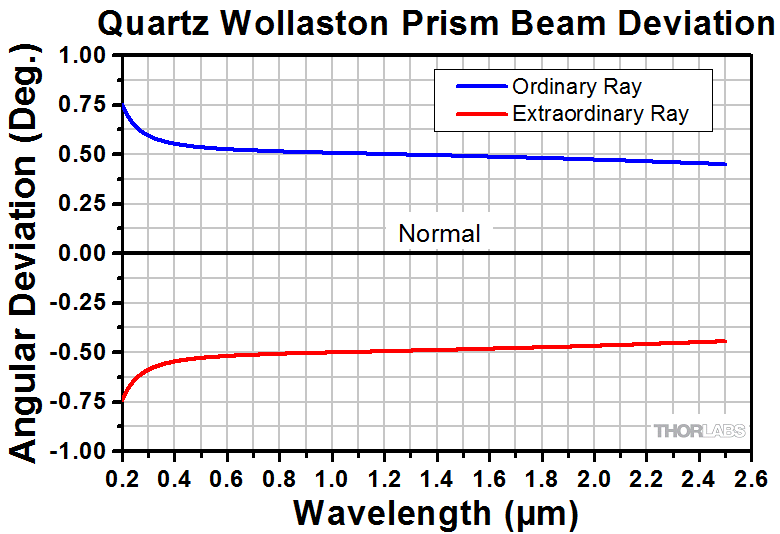
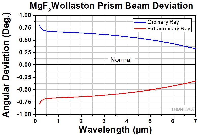
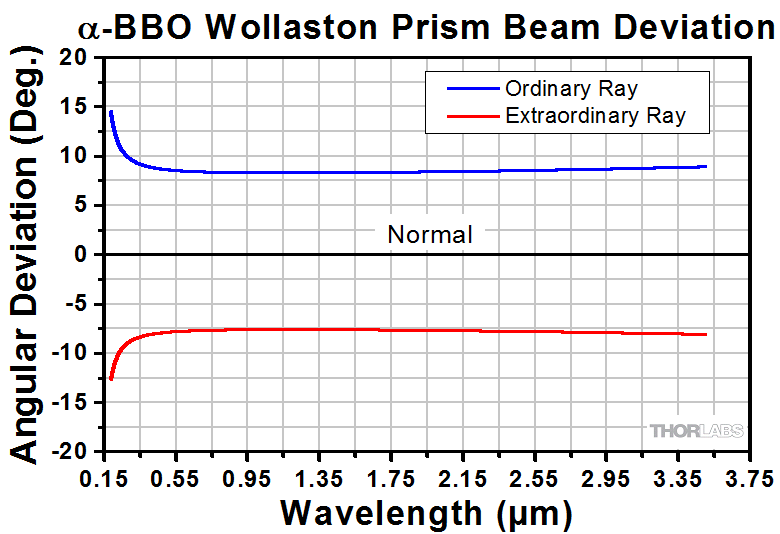
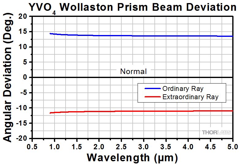
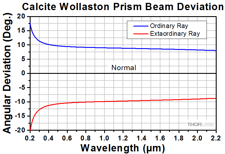
The output beams are separated by either a 1°, 1° 20', or 20° angle. The 20° separation angle versions are symmetric to each other within ~3°. Since the output deviations are wavelength dependent (see the Beam Deviation plots in the Graphs tab), Wollaston prisms have been used as polarization analyzers as well as in spectrometers.
| Birefringent Crystal Beamsplitters | ||
|---|---|---|
| Type | Ordinary Ray Anglea | Extraordinary Ray Anglea |
| Calcite Beam Displacers | Parallel | Parallel |
| YVO4 Beam Displacers | ||
| Rochon Prisms | Parallel | Deviated |
| Wollaston Prisms | Deviated | Deviated |
Our prisms have a number of substrate, mounting, and broadband anti-reflective (AR) coating options. These prisms come uncoated in substrates of quartz (400 - 2000 nm), magnesium fluoride (200 nm - 6.0 µm), YVO4 (yttrium orthovanadate, 900 nm - 3.4 µm), or calcite (350 - 2300 nm). Additionally, our α-BBO (190 - 3500 nm) prisms have a protective MgF2 coating, while calcite prisms are available in -A (350 - 700 nm) or -B (650 - 1050 nm) broadband AR coatings that have an average reflectance of <1% over their respective ranges; please see the Graphs tab for reflectance plots. Custom coatings are available, please contact Tech Support for details.
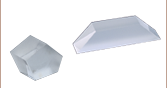
Our mounted prisms are sold in a Ø1" anodized aluminum, labeled housing. We also offer an uncoated, unmounted calcite Wollaston prism from stock for use in OEM applications. Care should be taken when handling this prism since calcite is a soft material that is easily scratched. For further information on the properties of calcite, please see the Calcite tab above. Please contact Tech Support for unmounted quartz, magnesium fluoride, or α-BBO prisms.
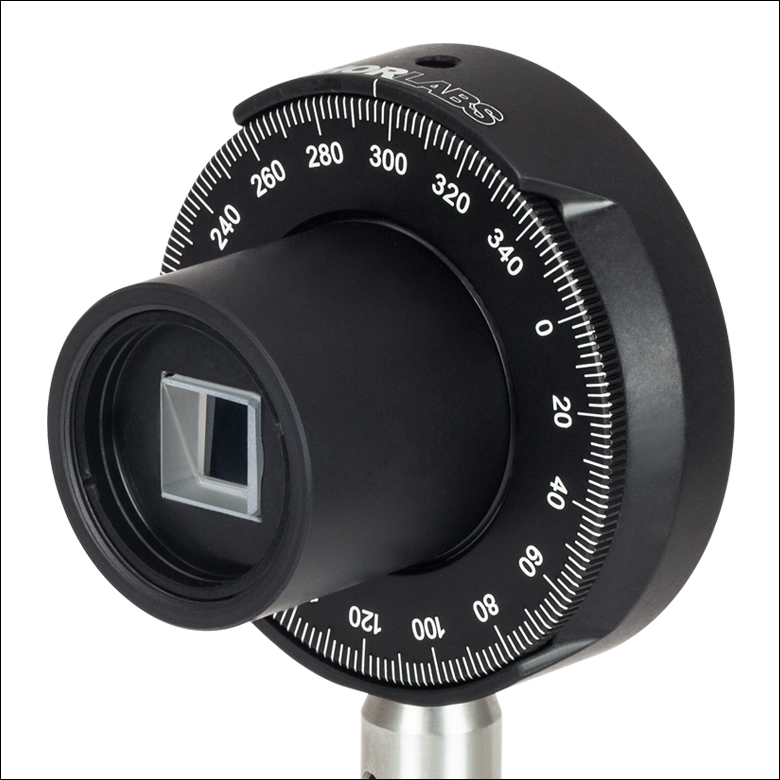
Wollaston prisms are commonly used in rotation mounts. Due to the thickness of our mounted prisms, they typically need to be mounted in an SM1 lens tube (i.e., Item # SM1L10) using an SM1RR retaining ring, which can then be threaded onto a rotation mount (see image above). The unmounted prisms can be mounted using one of our Kinematic Platform Mounts with a PM3 Clamping Arm.
Click to Enlarge
Theoretical data for the separation angle of the WPQ10 Wollaston Prism.
Click Here for Raw Data
Click to Enlarge
Theoretical data for the separation angle of the WPM10 Wollaston Prism.
Click Here for Raw Data
Click to Enlarge
Theoretical data for the separation angle of the WPA10 Wollaston Prism.
Click Here for Raw Data
Click to Enlarge
Theoretical data for the separation angle of the WPY10 Wollaston Prism.
Click Here for Raw Data
Click to Enlarge
Theoretical data for the separation angle of the WP10, WP10P, WP10-A, and WP10-B Wollaston Prisms.
Click Here for Raw Data
Click to Enlarge
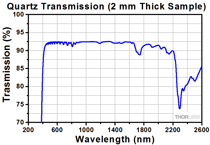
The graph above was obtained from two 1 mm thick plates of quartz, glued together with NOA68 adhesive, to best simulate the transmission through the WPQ10 Quartz Wollaston Prism.
Click Here for Raw Data
Click to Enlarge
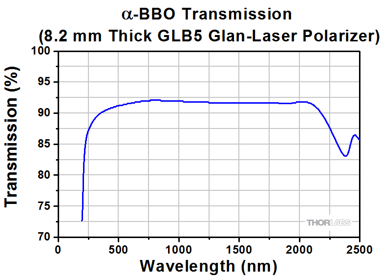
The graph above was measured for the GLB5 Glan-Laser Polarizer, which utilizes the same adhesive as the α-BBO Wollaston Prism.
Click Here for Raw Data
Click to Enlarge
The graph above was obtained from two plates of YVO4, glued together with NOA61 adhesive, to best simulate the transmission through the WPY10 prism.
Click Here for Raw Data
Click to Enlarge
The graph above was measured for the GTH10 Glan-Thompson Polarizer, which utilizes the same adhesive as the calcite Wollaston Prisms.
Click Here for Raw Data

Click to Enlarge
Theoretical data for the reflectance of the WP10-A (blue) and WP10-B (green) Wollaston Prisms.
Click Here for Raw Data
Wollaston Prism
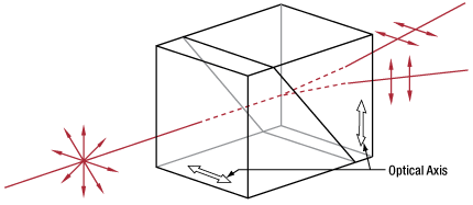
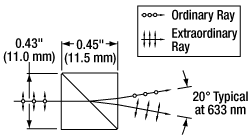
Our calcite polarizers are all based on high-grade, birefringent calcite crystals. Due to the birefringent nature of calcite, waves polarized in the direction of the optical axis propagate with a different index of refraction than waves polarized orthogonally to the optical axis. In our Wollaston prisms, this birefringence separates the two orthogonal polarization states of an incident beam. When unpolarized light is normally incident on the optic, extraordinary rays and ordinary rays exit through the opposite end of the prism at different angles, as shown in the image to the right.
A calcite polarizer can be designed as either a polarization splitter/combiner or as a polarizer element that removes the angled, orthogonally polarized component of a beam. Our calcite polarizers are typically built out of two prisms, as shown in the drawing to the right. Since calcite is a soft crystal that is easily damaged, almost all of our calcite polarizers are offered in metal housings. With convenient threadings and adapters, these housings can easily be mounted into our opto-mechanical products.
| Thorlabs' Calcite Polarizers | ||
|---|---|---|
| Glan-Laser Polarizers | Glan-Taylor Polarizers | Wollaston Polarizers |
| Mounted Glan-Thompson Polarizers Unmounted Glan-Thompson Polarizers |
Double Glan-Taylor Polarizer | Beam Displacers |
| Damage Threshold Specifications | ||
|---|---|---|
| Item # Prefix | Damage Threshold | |
| WP10 | Pulsed | 5 J/cm2 (1064 nm, 10 ns, 10 Hz, Ø0.476 mm) |
| CWa | 100 W/cm (1064 nm, Ø0.092 mm) | |
Damage Threshold Data for Thorlabs' Wollaston Prism
The specifications to the right are measured data for Thorlabs' Calcite Wollaston prisms.
Laser Induced Damage Threshold Tutorial
The following is a general overview of how laser induced damage thresholds are measured and how the values may be utilized in determining the appropriateness of an optic for a given application. When choosing optics, it is important to understand the Laser Induced Damage Threshold (LIDT) of the optics being used. The LIDT for an optic greatly depends on the type of laser you are using. Continuous wave (CW) lasers typically cause damage from thermal effects (absorption either in the coating or in the substrate). Pulsed lasers, on the other hand, often strip electrons from the lattice structure of an optic before causing thermal damage. Note that the guideline presented here assumes room temperature operation and optics in new condition (i.e., within scratch-dig spec, surface free of contamination, etc.). Because dust or other particles on the surface of an optic can cause damage at lower thresholds, we recommend keeping surfaces clean and free of debris. For more information on cleaning optics, please see our Optics Cleaning tutorial.
Testing Method
Thorlabs' LIDT testing is done in compliance with ISO/DIS 11254 and ISO 21254 specifications.
First, a low-power/energy beam is directed to the optic under test. The optic is exposed in 10 locations to this laser beam for 30 seconds (CW) or for a number of pulses (pulse repetition frequency specified). After exposure, the optic is examined by a microscope (~100X magnification) for any visible damage. The number of locations that are damaged at a particular power/energy level is recorded. Next, the power/energy is either increased or decreased and the optic is exposed at 10 new locations. This process is repeated until damage is observed. The damage threshold is then assigned to be the highest power/energy that the optic can withstand without causing damage. A histogram such as that below represents the testing of one BB1-E02 mirror.

The photograph above is a protected aluminum-coated mirror after LIDT testing. In this particular test, it handled 0.43 J/cm2 (1064 nm, 10 ns pulse, 10 Hz, Ø1.000 mm) before damage.

| Example Test Data | |||
|---|---|---|---|
| Fluence | # of Tested Locations | Locations with Damage | Locations Without Damage |
| 1.50 J/cm2 | 10 | 0 | 10 |
| 1.75 J/cm2 | 10 | 0 | 10 |
| 2.00 J/cm2 | 10 | 0 | 10 |
| 2.25 J/cm2 | 10 | 1 | 9 |
| 3.00 J/cm2 | 10 | 1 | 9 |
| 5.00 J/cm2 | 10 | 9 | 1 |
According to the test, the damage threshold of the mirror was 2.00 J/cm2 (532 nm, 10 ns pulse, 10 Hz, Ø0.803 mm). Please keep in mind that these tests are performed on clean optics, as dirt and contamination can significantly lower the damage threshold of a component. While the test results are only representative of one coating run, Thorlabs specifies damage threshold values that account for coating variances.
Continuous Wave and Long-Pulse Lasers
When an optic is damaged by a continuous wave (CW) laser, it is usually due to the melting of the surface as a result of absorbing the laser's energy or damage to the optical coating (antireflection) [1]. Pulsed lasers with pulse lengths longer than 1 µs can be treated as CW lasers for LIDT discussions.
When pulse lengths are between 1 ns and 1 µs, laser-induced damage can occur either because of absorption or a dielectric breakdown (therefore, a user must check both CW and pulsed LIDT). Absorption is either due to an intrinsic property of the optic or due to surface irregularities; thus LIDT values are only valid for optics meeting or exceeding the surface quality specifications given by a manufacturer. While many optics can handle high power CW lasers, cemented (e.g., achromatic doublets) or highly absorptive (e.g., ND filters) optics tend to have lower CW damage thresholds. These lower thresholds are due to absorption or scattering in the cement or metal coating.

LIDT in linear power density vs. pulse length and spot size. For long pulses to CW, linear power density becomes a constant with spot size. This graph was obtained from [1].

Pulsed lasers with high pulse repetition frequencies (PRF) may behave similarly to CW beams. Unfortunately, this is highly dependent on factors such as absorption and thermal diffusivity, so there is no reliable method for determining when a high PRF laser will damage an optic due to thermal effects. For beams with a high PRF both the average and peak powers must be compared to the equivalent CW power. Additionally, for highly transparent materials, there is little to no drop in the LIDT with increasing PRF.
In order to use the specified CW damage threshold of an optic, it is necessary to know the following:
- Wavelength of your laser
- Beam diameter of your beam (1/e2)
- Approximate intensity profile of your beam (e.g., Gaussian)
- Linear power density of your beam (total power divided by 1/e2 beam diameter)
Thorlabs expresses LIDT for CW lasers as a linear power density measured in W/cm. In this regime, the LIDT given as a linear power density can be applied to any beam diameter; one does not need to compute an adjusted LIDT to adjust for changes in spot size, as demonstrated by the graph to the right. Average linear power density can be calculated using the equation below.

The calculation above assumes a uniform beam intensity profile. You must now consider hotspots in the beam or other non-uniform intensity profiles and roughly calculate a maximum power density. For reference, a Gaussian beam typically has a maximum power density that is twice that of the uniform beam (see lower right).
Now compare the maximum power density to that which is specified as the LIDT for the optic. If the optic was tested at a wavelength other than your operating wavelength, the damage threshold must be scaled appropriately. A good rule of thumb is that the damage threshold has a linear relationship with wavelength such that as you move to shorter wavelengths, the damage threshold decreases (i.e., a LIDT of 10 W/cm at 1310 nm scales to 5 W/cm at 655 nm):

While this rule of thumb provides a general trend, it is not a quantitative analysis of LIDT vs wavelength. In CW applications, for instance, damage scales more strongly with absorption in the coating and substrate, which does not necessarily scale well with wavelength. While the above procedure provides a good rule of thumb for LIDT values, please contact Tech Support if your wavelength is different from the specified LIDT wavelength. If your power density is less than the adjusted LIDT of the optic, then the optic should work for your application.
Please note that we have a buffer built in between the specified damage thresholds online and the tests which we have done, which accommodates variation between batches. Upon request, we can provide individual test information and a testing certificate. The damage analysis will be carried out on a similar optic (customer's optic will not be damaged). Testing may result in additional costs or lead times. Contact Tech Support for more information.
Pulsed Lasers
As previously stated, pulsed lasers typically induce a different type of damage to the optic than CW lasers. Pulsed lasers often do not heat the optic enough to damage it; instead, pulsed lasers produce strong electric fields capable of inducing dielectric breakdown in the material. Unfortunately, it can be very difficult to compare the LIDT specification of an optic to your laser. There are multiple regimes in which a pulsed laser can damage an optic and this is based on the laser's pulse length. The highlighted columns in the table below outline the relevant pulse lengths for our specified LIDT values.
Pulses shorter than 10-9 s cannot be compared to our specified LIDT values with much reliability. In this ultra-short-pulse regime various mechanics, such as multiphoton-avalanche ionization, take over as the predominate damage mechanism [2]. In contrast, pulses between 10-7 s and 10-4 s may cause damage to an optic either because of dielectric breakdown or thermal effects. This means that both CW and pulsed damage thresholds must be compared to the laser beam to determine whether the optic is suitable for your application.
| Pulse Duration | t < 10-9 s | 10-9 < t < 10-7 s | 10-7 < t < 10-4 s | t > 10-4 s |
|---|---|---|---|---|
| Damage Mechanism | Avalanche Ionization | Dielectric Breakdown | Dielectric Breakdown or Thermal | Thermal |
| Relevant Damage Specification | No Comparison (See Above) | Pulsed | Pulsed and CW | CW |
When comparing an LIDT specified for a pulsed laser to your laser, it is essential to know the following:

LIDT in energy density vs. pulse length and spot size. For short pulses, energy density becomes a constant with spot size. This graph was obtained from [1].
- Wavelength of your laser
- Energy density of your beam (total energy divided by 1/e2 area)
- Pulse length of your laser
- Pulse repetition frequency (prf) of your laser
- Beam diameter of your laser (1/e2 )
- Approximate intensity profile of your beam (e.g., Gaussian)
The energy density of your beam should be calculated in terms of J/cm2. The graph to the right shows why expressing the LIDT as an energy density provides the best metric for short pulse sources. In this regime, the LIDT given as an energy density can be applied to any beam diameter; one does not need to compute an adjusted LIDT to adjust for changes in spot size. This calculation assumes a uniform beam intensity profile. You must now adjust this energy density to account for hotspots or other nonuniform intensity profiles and roughly calculate a maximum energy density. For reference a Gaussian beam typically has a maximum energy density that is twice that of the 1/e2 beam.
Now compare the maximum energy density to that which is specified as the LIDT for the optic. If the optic was tested at a wavelength other than your operating wavelength, the damage threshold must be scaled appropriately [3]. A good rule of thumb is that the damage threshold has an inverse square root relationship with wavelength such that as you move to shorter wavelengths, the damage threshold decreases (i.e., a LIDT of 1 J/cm2 at 1064 nm scales to 0.7 J/cm2 at 532 nm):

You now have a wavelength-adjusted energy density, which you will use in the following step.
Beam diameter is also important to know when comparing damage thresholds. While the LIDT, when expressed in units of J/cm², scales independently of spot size; large beam sizes are more likely to illuminate a larger number of defects which can lead to greater variances in the LIDT [4]. For data presented here, a <1 mm beam size was used to measure the LIDT. For beams sizes greater than 5 mm, the LIDT (J/cm2) will not scale independently of beam diameter due to the larger size beam exposing more defects.
The pulse length must now be compensated for. The longer the pulse duration, the more energy the optic can handle. For pulse widths between 1 - 100 ns, an approximation is as follows:

Use this formula to calculate the Adjusted LIDT for an optic based on your pulse length. If your maximum energy density is less than this adjusted LIDT maximum energy density, then the optic should be suitable for your application. Keep in mind that this calculation is only used for pulses between 10-9 s and 10-7 s. For pulses between 10-7 s and 10-4 s, the CW LIDT must also be checked before deeming the optic appropriate for your application.
Please note that we have a buffer built in between the specified damage thresholds online and the tests which we have done, which accommodates variation between batches. Upon request, we can provide individual test information and a testing certificate. Contact Tech Support for more information.
[1] R. M. Wood, Optics and Laser Tech. 29, 517 (1998).
[2] Roger M. Wood, Laser-Induced Damage of Optical Materials (Institute of Physics Publishing, Philadelphia, PA, 2003).
[3] C. W. Carr et al., Phys. Rev. Lett. 91, 127402 (2003).
[4] N. Bloembergen, Appl. Opt. 12, 661 (1973).

In order to illustrate the process of determining whether a given laser system will damage an optic, a number of example calculations of laser induced damage threshold are given below. For assistance with performing similar calculations, we provide a spreadsheet calculator that can be downloaded by clicking the button to the right. To use the calculator, enter the specified LIDT value of the optic under consideration and the relevant parameters of your laser system in the green boxes. The spreadsheet will then calculate a linear power density for CW and pulsed systems, as well as an energy density value for pulsed systems. These values are used to calculate adjusted, scaled LIDT values for the optics based on accepted scaling laws. This calculator assumes a Gaussian beam profile, so a correction factor must be introduced for other beam shapes (uniform, etc.). The LIDT scaling laws are determined from empirical relationships; their accuracy is not guaranteed. Remember that absorption by optics or coatings can significantly reduce LIDT in some spectral regions. These LIDT values are not valid for ultrashort pulses less than one nanosecond in duration.
A Gaussian beam profile has about twice the maximum intensity of a uniform beam profile.
CW Laser Example
Suppose that a CW laser system at 1319 nm produces a 0.5 W Gaussian beam that has a 1/e2 diameter of 10 mm. A naive calculation of the average linear power density of this beam would yield a value of 0.5 W/cm, given by the total power divided by the beam diameter:
However, the maximum power density of a Gaussian beam is about twice the maximum power density of a uniform beam, as shown in the graph to the right. Therefore, a more accurate determination of the maximum linear power density of the system is 1 W/cm.
An AC127-030-C achromatic doublet lens has a specified CW LIDT of 350 W/cm, as tested at 1550 nm. CW damage threshold values typically scale directly with the wavelength of the laser source, so this yields an adjusted LIDT value:
The adjusted LIDT value of 350 W/cm x (1319 nm / 1550 nm) = 298 W/cm is significantly higher than the calculated maximum linear power density of the laser system, so it would be safe to use this doublet lens for this application.
Pulsed Nanosecond Laser Example: Scaling for Different Pulse Durations
Suppose that a pulsed Nd:YAG laser system is frequency tripled to produce a 10 Hz output, consisting of 2 ns output pulses at 355 nm, each with 1 J of energy, in a Gaussian beam with a 1.9 cm beam diameter (1/e2). The average energy density of each pulse is found by dividing the pulse energy by the beam area:

As described above, the maximum energy density of a Gaussian beam is about twice the average energy density. So, the maximum energy density of this beam is ~0.7 J/cm2.
The energy density of the beam can be compared to the LIDT values of 1 J/cm2 and 3.5 J/cm2 for a BB1-E01 broadband dielectric mirror and an NB1-K08 Nd:YAG laser line mirror, respectively. Both of these LIDT values, while measured at 355 nm, were determined with a 10 ns pulsed laser at 10 Hz. Therefore, an adjustment must be applied for the shorter pulse duration of the system under consideration. As described on the previous tab, LIDT values in the nanosecond pulse regime scale with the square root of the laser pulse duration:
This adjustment factor results in LIDT values of 0.45 J/cm2 for the BB1-E01 broadband mirror and 1.6 J/cm2 for the Nd:YAG laser line mirror, which are to be compared with the 0.7 J/cm2 maximum energy density of the beam. While the broadband mirror would likely be damaged by the laser, the more specialized laser line mirror is appropriate for use with this system.
Pulsed Nanosecond Laser Example: Scaling for Different Wavelengths
Suppose that a pulsed laser system emits 10 ns pulses at 2.5 Hz, each with 100 mJ of energy at 1064 nm in a 16 mm diameter beam (1/e2) that must be attenuated with a neutral density filter. For a Gaussian output, these specifications result in a maximum energy density of 0.1 J/cm2. The damage threshold of an NDUV10A Ø25 mm, OD 1.0, reflective neutral density filter is 0.05 J/cm2 for 10 ns pulses at 355 nm, while the damage threshold of the similar NE10A absorptive filter is 10 J/cm2 for 10 ns pulses at 532 nm. As described on the previous tab, the LIDT value of an optic scales with the square root of the wavelength in the nanosecond pulse regime:
This scaling gives adjusted LIDT values of 0.08 J/cm2 for the reflective filter and 14 J/cm2 for the absorptive filter. In this case, the absorptive filter is the best choice in order to avoid optical damage.
Pulsed Microsecond Laser Example
Consider a laser system that produces 1 µs pulses, each containing 150 µJ of energy at a repetition rate of 50 kHz, resulting in a relatively high duty cycle of 5%. This system falls somewhere between the regimes of CW and pulsed laser induced damage, and could potentially damage an optic by mechanisms associated with either regime. As a result, both CW and pulsed LIDT values must be compared to the properties of the laser system to ensure safe operation.
If this relatively long-pulse laser emits a Gaussian 12.7 mm diameter beam (1/e2) at 980 nm, then the resulting output has a linear power density of 5.9 W/cm and an energy density of 1.2 x 10⁻⁴ J/cm2 per pulse. This can be compared to the LIDT values for a WPQ10E-980 polymer zero-order quarter-wave plate, which are 5 W/cm for CW radiation at 810 nm and 5 J/cm2 for a 10 ns pulse at 810 nm. As before, the CW LIDT of the optic scales linearly with the laser wavelength, resulting in an adjusted CW value of 6 W/cm at 980 nm. On the other hand, the pulsed LIDT scales with the square root of the laser wavelength and the square root of the pulse duration, resulting in an adjusted value of 55 J/cm2 for a 1 µs pulse at 980 nm. The pulsed LIDT of the optic is significantly greater than the energy density of the laser pulse, so individual pulses will not damage the wave plate. However, the large average linear power density of the laser system may cause thermal damage to the optic, much like a high-power CW beam.
| Posted Comments: | |
Mika C
(posted 2023-07-26 18:06:22.883) Is it possible to get a C-coated WP10 prism? Thanks! jdelia
(posted 2023-07-27 11:44:58.0) Thank you for contacting Thorlabs. I have reached out to you directly to discuss the feasibility of your custom request. Wei Liu
(posted 2022-08-11 09:59:19.453) Hi, Thorlabs Technical Team,
Our lab have bought a specified product for use in our high-power femtosecond laser system, but from your LDIT page, there is no relevant information regarding the LDIT in that regime, so here I want to know whether this product is suitable for our laser system. And here is the information of our laser system: Output Power: 4W, pulse width: ~140fs, repetition rate: 80MHz.
I am looking forward to your reply, thanks. jgreschler
(posted 2022-08-15 11:13:48.0) Thank you for reaching out to Thorlabs. Unfortunately we currently do not have femtosecond damage data for this product line. Boris Safonov
(posted 2022-01-27 04:05:29.633) Please indicate what is the angle between the entrance surface and the splitting surface for WPA10. cdolbashian
(posted 2022-02-04 03:39:31.0) Thank you for reaching out to us at Thorlabs! The angle between prism halves, for all of the Wollaston prisms, is 45 degrees. Francois Parnet
(posted 2021-02-23 10:05:27.847) What are the damage threshold for continuous and pulsed lasers for the WPA10 component ? YLohia
(posted 2021-04-14 02:36:22.0) Unfortunately, we don't have formal damage threshold specs for the WPA10 at the moment. Based on our direct discussion, we expect the high average powers (50 Watts CW / 0.5 mJ pulsed) you are going to be using might be a problem for the cement of the WPA10. user
(posted 2019-04-10 13:07:47.35) What is the error of the separation angle at 633 nm? YLohia
(posted 2019-04-29 11:09:57.0) Hello, thank you for contacting Thorlabs. I reached out to you directly at the time of this posting to gather more details regarding the specific item you are referring to and your application. Please email techsupport@thorlabs.com if you have any further questions. optel.opole
(posted 2019-01-11 13:15:32.257) Does the mounted Wollaston prism poses thread on both sides (in and out). Can it be integrated (screwed on) 1" lens tube. YLohia
(posted 2019-01-11 04:08:33.0) Hello, the mounted prisms do not have SM1 threads on any side. They are meant to be placed inside SM1 lens tubes and sandwiched between two SM1RR retaining rings. More information is given in the Overview tab of this page. christian.schmidt
(posted 2018-02-01 12:46:04.92) Dear sir or medam,
we are thinking about using the WP to separate two laser beams from each other, which travel towards each other where one is s- and one is p-polarized. (Usually a polarizing beam splitter is used for that, but due to spatial limitations we cannot use them.) Is that possible with a WP? And why is there a preferred side for the beam entrance at a WP? Thank you very much.
Best regards
Christian nbayconich
(posted 2018-03-30 03:22:19.0) Thank you for contacting Thorlabs. Yes you can use a Wollaston prism to separate two orthogonal polarization states of light from each other and you can technically combine two orthogonally polarized sources using the opposite aperture of the prism. Are you trying to combine or separate your polarization states?
Birefringent crystals such as these can be used in the opposite direction but that's assuming to combine two orthogonal polarization states. Launching a randomly polarized source into the opposite direction of the prism (vertically cut optical axis) will not result in the same two orthogonally polarized states as shown in our Calcite tutorial diagram. a11111a4210
(posted 2017-07-12 13:06:07.543) is there a Wollaston Prisms which can emit parallel light in your product? tcampbell
(posted 2017-07-21 11:37:57.0) Hello, thank you for contacting Thorlabs. You may be interested in our Calcite Beam Displacers, which can be found here:
https://www.thorlabs.com/newgrouppage9.cfm?objectgroup_id=745
We have added a Birefringent Crystal Beamsplitters selection guide to aid in distinguishing these items. plauria
(posted 2016-08-02 11:14:20.567) We have a couple of these prisms for their high extinction ratio. But our beam overfills the wollostan aperture. I was wondering if the extinction ratio degrades if you sent converging light through it (e.g. focusing using a lens)? Or does it not matter? tholste
(posted 2012-07-27 17:09:00.0) A response from Tor at Thorlabs to A.J.H.: Thank you for your inquiry! Unfortunately we do not have transmission data for our Wollaston prisms at this time. The transmission should be very close to that of our Glan-Laser Polarizers, as they are both composed of calcite and use the same coatings. You can find the transmission for these here: http://www.thorlabs.com/NewGroupPage9.cfm?ObjectGroup_ID=917. I hope this helps - please do not hesitate to contact techsupport@thorlabs.com if you have further inquiries. a.j.h.meskers
(posted 2012-07-25 08:51:02.0) Dear Sir/Madam,
For this product you display a graph showing the reflectance of the AR coating, I would also like to see how the tranmissivity of this crystal vs the wavelength. Do you have data regarding this?
Kind regards,
Arjan Meskers
PhD-researcher
Delft University of Technology
Faculty: Mechanical, Maritime and Materials Engineering (3mE)
Department: Precision and Microsystems Engineering (PME)
Section: Mechatronic System Design (MSD), Metrology
Mekelweg 2, 2628 CD Delft, The Netherlands
Room 5A-2-28
Phone (+31) 15 27 83905
Email A.J.H.Meskers@TUDelft.nl
Webpage www.PME.tudelft.nl Thorlabs
(posted 2010-11-02 17:12:17.0) Response from Javier at Thorlabs to kjsong: Thank you for your feedback. We will work on specifying temperature specs for this prism. I will contact you directly to discuss your application. kjsong
(posted 2010-11-02 11:50:09.0) It would be very helpful if Thorlabs put in the overview that WP10 (I bought two pieces recently) is temperature variation sensitive and easily "cracks". Also it should warn potential users that due to lack of AR coating, the two reflections are quite strong. Since the other calcite polarizers are not sensitive to temperature variation, I wonder whats so special about WP?
KJS user
(posted 2009-03-21 15:26:38.0) the drawing on the tab named drawing is low res and hard to read Tyler
(posted 2008-05-12 11:57:39.0) Response from Tyler at Thorlabs to j.d.ellis: The beam deviation angle as a function of wavelength can be found under the "Graphs" tab. Typical index of refraction data was used to make the plot of the deviation angle as a function of wavelength. Since we use natural calcite to make our Wollaston prisms we cannot provide specific index of refraction data. The angle between the entrance face of the Wollaston prism and the splitting surface is 45 degrees +/- 3 arcmin. Thank you for you interest in our product and if you still have questions regarding the suitability of our product for your application please contact our technical support department or leave some additional questions and information about your application in our feedback forum. j.d.ellis
(posted 2008-05-07 05:47:08.0) The output beam diameter is quoted as 20 degrees. Should I assume thats at 633 nm? Also, What is the difference between the ordinary refractive index and the extraordinary refractive index (at 633 nm)? "Heighest grade optical calcite" isnt specific enough to determine these values. What is the angle between the entrance face and the splitting surface? These are all things that should be listed under the "specs" section. Laurie
(posted 2008-04-09 16:44:41.0) Response from Laurie at Throlabs to surajdsp: Someone from our techsupport staff will be contacting you via email to discuss your application and possible solutions. Thank you for your interest in our products! surajdsp
(posted 2008-04-09 07:09:11.0) Dear Sir,
we are working on current measurement using faraday effect. We are in need of integrated wollastom prism with fiber connector at each end. We have already a laser source 630nm PM fiber 60 meter. So we want to connect wollastom prism at the output of the fiber. You are kindly requested to send the quotation for the same. Intergated wollastam prism with fiber connectors at each end.
Suraj Pardeshi
Sr.Engineer
ERDA
Vadodara
INDIA
M:099908299184
fax:091-0265-2638382
surajdsp@gmail.com |
Polarizer Selection Guide
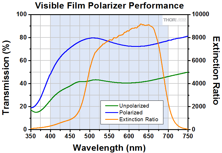
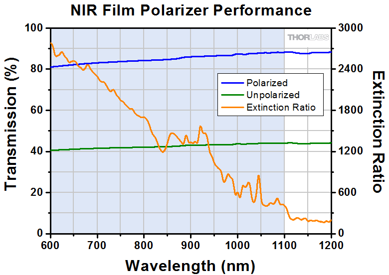
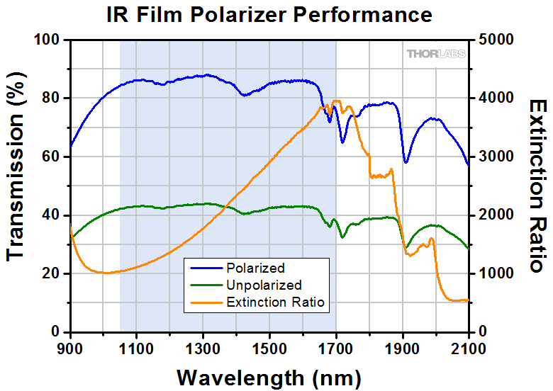
Thorlabs offers a diverse range of polarizers, including wire grid, film, calcite, alpha-BBO, rutile, and beamsplitting polarizers. Collectively, our line of wire grid polarizers offers coverage from the visible range to the beginning of the Far-IR range. Our nanoparticle linear film polarizers provide extinction ratios as high as 100 000:1. Alternatively, our other film polarizers offer an affordable solution for polarizing light from the visible to the Near-IR. Next, our beamsplitting polarizers allow for use of the reflected beam, as well as the more completely polarized transmitted beam. Finally, our alpha-BBO (UV), calcite (visible to Near-IR), rutile (Near-IR to Mid-IR), and yttrium orthovanadate (YVO4) (Near-IR to Mid-IR) polarizers each offer an exceptional extinction ratio of 100 000:1 within their respective wavelength ranges.
To explore the available types, wavelength ranges, extinction ratios, transmission, and available sizes for each polarizer category, click More [+] in the appropriate row below.
| Wire Grid Polarizers |
|---|

| Film Polarizers |
|---|


| Beamsplitting Polarizers |
|---|
| Polarizer Type | Wavelength Range | Extinction Ratio | Transmissiona | Available Sizes |
| Polarizing Plate Beamsplitters | 405 nm | >10 000:1 | Ø1" and 25 mm x 36 mm | |
| 532 nm | ||||
| 633 nm | ||||
| 780 nm | ||||
| 808 nm | ||||
| 1030 nm | ||||
| 1064 nm | ||||
| 1310 nm | ||||
| 1550 nm | ||||
| Polarizing Bandpass Filters | 355 nm +6 nm / -9 nm | 1 000 000:1 | 25.2 mm x 35.6 mm | |
| Broadband Polarizing Beamsplitter Cubes (Unmounted, 16 mm Cage Cube, or 30 mm Cage Cube) |
420 nm - 680 nm | 1000:1e |  |
5 mm, 10 mm, 1/2", 20 mmf, 1"f, and 2" |
| 620 nm - 1000 nm |  |
|||
| 700 nm - 1300 nm | 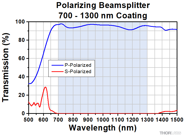 |
|||
| 900 nm - 1300 nm | 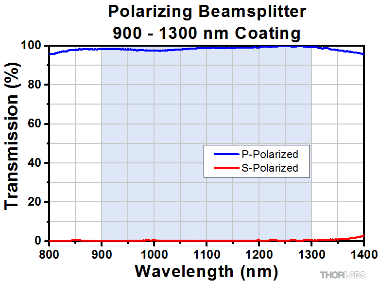 |
|||
| 1200 nm - 1600 nm |  |
|||
| Wire Grid Polarizing Beamsplitter Cubes (Unmounted or 30 mm Cage Cube) |
400 nm - 700 nm | >1 000:1 (AOI: 0° - 5°) >100:1 (AOI: 0° - 25°) |
 P-Pol. S-Pol. |
1"f |
| Laser-Line Polarizing Beamsplitter Cubes (Unmounted or 30 mm Cage Cube) |
532 nm | 3000:1 |  |
10 mm, 1/2", 1"f |
| 633 nm |  |
|||
| 780 nm |  |
|||
| 980 nm | 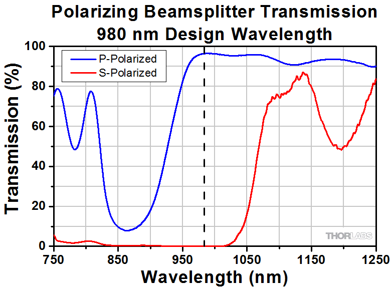 |
1"f | ||
| 1064 nm | 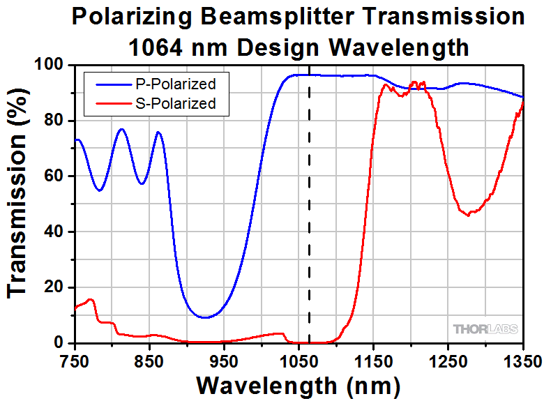 |
10 mm, 1/2", 1"f | ||
| 1550 nm | 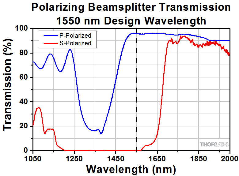 |
|||
| High-Power Laser-Line Polarizing Beamsplitter Cubes (Unmounted or 30 mm Cage Cube) | 355 nm | 2000:1 | 1/2" and 1"f | |
| 405 nm | 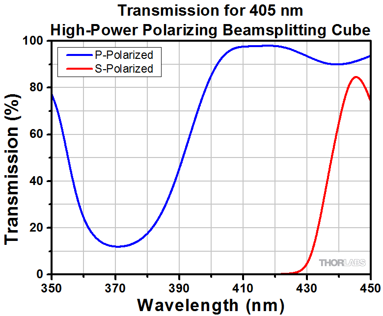 |
|||
| 532 nm | ||||
| 633 nm | ||||
| 780 - 808 nm |  |
|||
| 1064 nm | ||||
| High-Power, Broadband, High Extinction Ratio Polarizers | 700 nm - 1100 nm | > 1000:1 (700 - 1100 nm) > 5000:1 (750 - 1000 nm) > 10 000:1 (800 - 900 nm) |
12.7 mm (Input/Output Face, Square) |
|
| 900 nm - 1300 nm | >1000:1 (900 - 1300 nm) >10 000:1 (900 - 1250 nm) >100 000:1 (980 - 1080 nm) |
10 mm and 5 mm (Input/Output Face, Square) |
||
| Calcite Beam Displacers | 350 nmg - 2.3 µm (Uncoated) | - | 10 mmb (Clear Aperture, Square) |
|
| Yttrium Orthovanadate (YVO4) Beam Displacers | 488 nm - 3.4 µm (Uncoated) | - | >3 mm x 5 mm Ellipseh (Clear Aperture) |
|
| 2000 nm (V Coated) |
| alpha-BBO Polarizers |
|---|
| Calcite Polarizers |
|---|
| Quartz Polarizers |
|---|
| Magnesium Fluoride Polarizers |
|---|
| Yttrium Orthovanadate (YVO4) Polarizers |
|---|
| Rutile Polarizers |
|---|

 Zoom
Zoom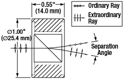
Schematic and Ray Diagram for Our Mounted Wollaston Polarizers
- Four Substrate Options Available
- Quartz: 400 nm - 2.0 µm
- Magnesium Fluoride: 200 nm - 6.0 µm
- α-BBO: 190 nm - 3.5 µm
- Calcite: 350 nm - 2.3 µm
- YVO4 (Yttrium Orthovanadate): 900 nm to 3.4 µm
- Ø1" Aluminum Housing Protects Prisms from Damage
- Options for 1°, 1° 20', or 20° Separation Angle
- Calcite Prisms Available with Two AR Coatings
- WP10-A: 350 nm - 700 nm
- WP10-B: 650 nm - 1050 nm
These Wollaston Prisms are mounted in a Ø1" anodized aluminum housing to protect the prism from damage. They are available uncoated in four materials (quartz, magnesium fluoride, calcite, or YVO4). The α-BBO prism is coated with a protective MgF2 coating while the calcite prisms are coated with one of two AR coatings. The quartz and magnesium fluoride prisms provide 1° or 1° 20' angle separation, respectively, while the α-BBO, calcite, and YVO4 prisms provide a larger, 20° angle separation (see the Beam Deviation plots in the table below or in the Graphs tab). The WPA10 features a MgF2 coating on the substrate, which serves as a protective layer that prevents the hygroscopic α-BBO substrate from interacting with moisture in the environment. This coating does not affect the optical properties of the prism.
The calcite prisms are also offered in two options for AR coatings on the input and output faces. The WP10-A is AR-coated for 350 - 700 nm, while the WP10-B is AR-coated for 650 - 1050 nm.
Please note that the Wollaston prism is adhered to the housing and cannot be removed. An unmounted calcite prism is available below for OEM applications. Contact Tech Support for custom coatings or unmounted prisms of any substrate type.
| Item # | WPQ10 | WPM10 | WPA10 | WP10 | WP10-A | WP10-B | WPY10 |
|---|---|---|---|---|---|---|---|
| Extinction Ratioa | >10 000:1 | >100 000:1 | |||||
| Substrate Wavelength Range |
400 nm to 2.0 μm | 200 nm to 6.0 μm | 190 nm to 3.5 μm | 350 nm to 2.3 μmb | 900 nm - 3.4 µm | ||
| Beam Separation Angle (Typical) | 1° at 633 nm | 1° 20' at 633 nm | 20° at 250 nm | 20° at 633 nm | |||
| Beam Deviation Graphc (Click to Enlarge) |
|
|
|
|
|
||
| Coating | Uncoated | Uncoated | Protective MgF2 | Uncoated | AR Coated | Uncoated | |
| AR Coating Wavelength Range |
N/A | 350 - 700 nm | 650 - 1050 nm | N/A | |||
| Clear Aperture | Ø10.0 mm | ||||||
| Transmitted Wavefront Error | <λ/4 at 632.8 nm | ||||||
| Surface Quality | 20-10 Scratch-Dig | ||||||
| Substrate | Crystal Quartz | Magnesium Fluorided | α-BBOd | Scatter-Free Calcited | YVO4d | ||

 Zoom
Zoom| Item # | WP10P |
|---|---|
| Extinction Ratioa | >100 000:1 |
| Substrate Wavelength Range | 350 nm to 2.3 μmb |
| Beam Separation Angle (Typical) | 20° at 633 nm |
| Beam Deviation Graphc (Click to Enlarge) |
|
| Clear Aperture | Ø10.0 mm |
| Transmitted Wavefront Error | <λ/4 at 632.8 nm |
| Surface Quality | 20-10 Scratch-Dig |
| Substrate | Scatter-Free Calcited |
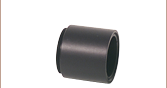
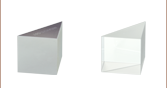
- Unmounted Calcite Wollaston Prism
- Ideal for OEM Applications
- Provides a 20° Separation Angle
This calcite Wollaston Prism is sold unmounted and is ideal for use in OEM applications. The dot on the polarizer indicates which prism should be used for the entrance beam. The transmittance of calcite near 350 nm is typically around 75%; for applications in the UV, we suggest using the α-BBO prism (sold above) as it offer superior UV transmittance.
Schematic and Ray Diagram for Our Unmounted Wollaston Polarizers