 Products Home
Scanning-Slit Optical Beam Profilers
- Wavelength Ranges from 200 to 2700 nm
- For Near-Gaussian Beams from Ø2.5 µm to Ø9 mm
- Scanning-Slit and Knife-Edge Operating Modes
BP209-VIS
Post and Post Holder
Sold Separately
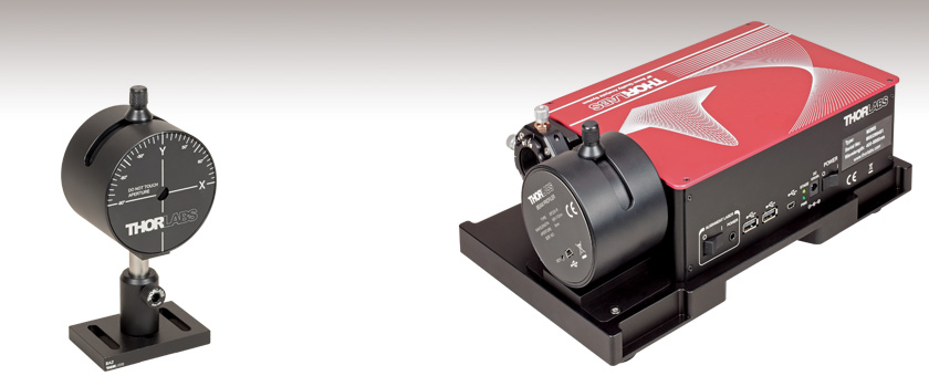
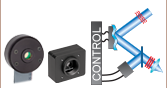
Application Idea
For a complete beam quality measurement system, integrate a beam profiler with an M2 measurement extension set. (Shown: BP209-IR2 and M2MS)


Please Wait
Click to Enlarge
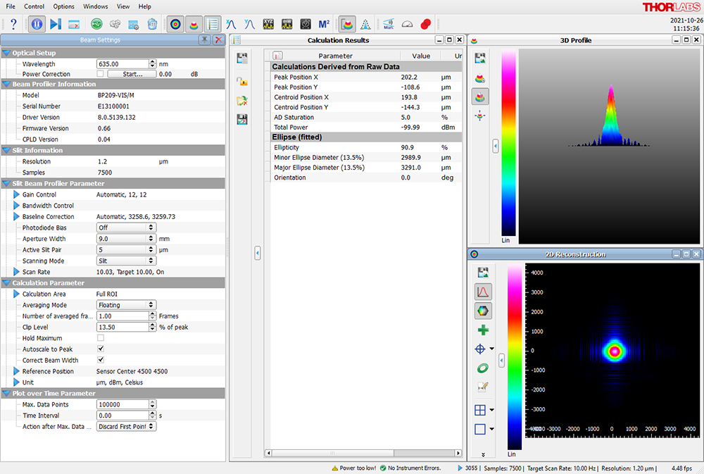
One Possible Configuration of the Beam Software GUI Showing Beam Settings, Calculation Results, 2D Reconstruction, and 3D Profile
Features
- Three Dual Scanning Slit Beam Profiler Models
- Item # BP209-VIS(/M) for 200 nm - 1100 nm
- Item # BP209IR1(/M) for 500 nm - 1700 nm
- Item # BP209-IR2(/M) for 900 nm - 2700 nm
- High-Precision Analysis of Near-Gaussian Beam Quality
- Reconstructs 2D and Pseudo 3D Spatial Power Distribution
- Single Stand-Alone Measurement Head
- Characterizes Continuous Wave or ≥10 Hz Pulsed Laser Emission
- Scanning Speeds from 2 to 20 Hz
- User-Calibratable Power Readout (See Manual for User-Calibration Procedure)
- Dynamic Range of 78 dB
- Low-Noise Amplifier
- High-Speed USB 2.0 Interface to PC
- Mounting Adapter Enables Compatibility with a 30 mm Cage System
Thorlabs' Dual Scanning Slit Beam Profilers are ideal for analyzing cross sectional profiles of near-Gaussian laser beams. Measurements of the intensity profiles along the user-specified X and Y axes of the beam's cross section are acquired at scan rates between 2 Hz and 20 Hz, which can be set using the software. The fast 20 Hz scan rate enables real-time optical system alignment. While these beam profilers are primarily intended for CW laser beams, ≥10 Hz pulsed beams can also be measured using an averaging technique (see the Operation tab for more information). These measurements can be used for beam quality evaluation, examination of the reconstructed beam profile, and monitoring long-term stability.
All three Dual Scanning Slit Beam Profiler Models have a Ø9 mm physical input aperture and make measurements by sequentially scanning two slits with the same width and orthogonal orientations across the input laser beam. The software enables users to switch between pairs of 5 µm or 25 µm width slits, select scanning-slit or knife-edge mode operation, and set a range of scan options. For information about the functionality and the usage of the different slit widths and operating modes, please see the Operation tab.
These scanning slit beam profilers are equipped with low-noise electronics, have a high dynamic range of 78 dB, and are capable of measuring beams with diameters between 2.5 µm and 9 mm. The beam diameter is measured in accordance with the ISO 11146 standard and can be displayed using a number of industry-standard clip levels, such as 1/e2 (13.5%), 50%, or an arbitrary clip level set by the user. When the beam of interest does not have a near-Gaussian beam shape, or when single-shot measurements of pulsed beams are required, we recommend our CMOS Camera Beam Profilers.
Thorlabs' Beam software offers complete control over the operation of these beam profilers, providing a broad range of user-adjustable settings as well as display and data logging options. The software can be downloaded from the Software tab and installed on a user-supplied PC. When the beam profiler is connected to a PC running the Beam software, no additional hardware or power supply is required. Thorlabs utilizes a high-speed USB 2.0 interface to connect the measurement head with the PC, and the required USB cable is included with the BP209 package. Flexible data export options as well as a data interface for National Instruments® software ease the integration of these profilers into customized data processing environments. Information about installing drivers, file locations, and reference notes for interfacing with our beam profilers using LabVIEW™, C, Visual C#, and Python are available in the user manual, which can be found by clicking on the red Docs icon (![]() ) next to the item number. Please see the User Interface tab or the user manual for more details on the functionality of the software.
) next to the item number. Please see the User Interface tab or the user manual for more details on the functionality of the software.
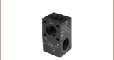
To mount a scanning slit optical beam profiler in a 30 mm cage system, the BPS209CSA(/M) mounting adapter (available below) can be used. Four Ø6 mm bores provide compatibiltiy with our Ø6 mm cage rods (not included).
M2 Measurement Systems
A complete M2 measurement system based on a BP209 beam profiler can be built by integrating the profiler with a wavelength-compatible extension set, available below. Information about all of Thorlabs' M2 measurement systems, as well as the option to configure and purchase a system with the BP209 beam profiler of your choice, can be found on the
| Item # | BP209-VIS | BP209-VIS/M | BP209IR1 | BP209IR1/M | BP209-IR2 | BP209-IR2/M |
|---|---|---|---|---|---|---|
| Beam Profiler Specifications | ||||||
| Wavelength Range | 200 - 1100 nm | 500 - 1700 nm | 900 - 2700 nm | |||
| Detector Material | UV-Enhanced Si | InGaAs | Extended InGaAs | |||
| Aperture Diameter | 9 mm | |||||
| Scan Methods | Scanning Slits, Knife Edge | |||||
| Slit Size | 5 µm and 25 µm | |||||
| Minimum Beam Diameter | 2.5 µm | |||||
| Maximum Beam Diameter | 9 mma | |||||
| Scan Rate | 2.0 - 20.0 Hz (Continuously Variable) | |||||
| Sampling Resolution | 0.12 - 1.24 µm (Depending on Scan Rate) | |||||
| Power Range | 1 µW - 10 W (Depending on Beam Diameter and Model; See Plot Below Right) | |||||
| Amplifier Bandwidth | 16 to 1000 kHz in 11 Steps (@ -1 dB) | |||||
| Sample Frequency | 0.2872 - 2.0 MHz | |||||
| Dynamic Range | 78 dB (Amplifier Switchable) | |||||
| PD Reverse Bias Voltage | 0 / -1.5 V (Switchable) | 0 V | ||||
| Signal Digitization | 15 Bit | |||||
| Dimensionsb | Ø79.5 mm x 60.0 mm (Ø3.13" x 2.36") Including Rotation Mount | |||||
| Minimum Pulse Rate | 10 Hzc | |||||
| Warm-Up Time for Rated Accuracy | 15 min | |||||
| Software | ||||||
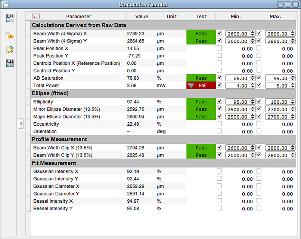
| Displayed Parameters/Features | X-Y-Profile, Centroid Position, Peak Position, Pseudo 3D Profile, Beam Width Clip Level/Second Moment (4σ), Gaussian Fit Applicable, Pass/Fail Test with Color-Coded Results |
|||||
| Compliant to Norm | ISO 11146 (Beam Widths, Divergence Angle and Beam Propagation Factor) | |||||
| Minimum System Requirements | Windows® 8.1 or Later, USB 2.0 High Speed Port, 4.0 GB RAM | |||||
| M² Analysis System (M2 Extension Set Available Separately) | ||||||
| Compatible M² Extension Set(s)d | M2MS or M2MS-AL | M2MS | ||||
| Compliant to Norm | ISO 11146 | |||||
| Measured Parameterse | M², Waist Width, Waist Position, Rayleigh Length, Divergence, Beam Pointing, Waist Asymmetry, Astigmatism | |||||
| Environmental | ||||||
| Operating Temperature | 5 °C to 35 °C | |||||
| Storage Temperature | -40 °C to 70 °C | |||||
All technical data are valid at 23 °C ± 5 °C and 45 ± 15% relative humidity.
Click to Enlarge
These maximum and minimum beam power limits are provided as functions of 1/e2 beam diameter for knife-edge and scanning-slit measurements and may not apply to measurements of total power. Please see the Operation tab for more information. To prevent thermal damage to the measurement head, do not operate for longer than 5 s with input powers exceeding 1 W.

Slit and Photodiode Position
Accurate measurements require a ≤Ø9 mm beam to be centered in the entrance aperture, the slits to scan the entire beam, and all transmitted power to be incident on the photosensitive surface of the photodetector. The drawings below show the distances of the slit location and the position of the photosensitive surface of the photodiode from the front face of the entrance aperature. These dimensions are provided to help the user ensure that the optical input, especially in the case of a highly diverent beam, is not clipped by the entrance pupil and does not overfill the photosensitive surface of the photodetector.

Click to Enlarge
An example of operation in Knife-Edge Mode, when the beam diameter is less than the slit width, is shown above.
Scanning-Slit and Knife-Edge Techniques
The BP209 series of Scanning Slit Beam Profilers analyze near-Gaussian, elliptical (or circular) free-space optical beams using either the scanning-slit or the knife-edge technique, depending on the diameter of the beam. These approaches scan two slits, one after the other, across the full cross section of the beam. One slit is scanned along the X axis of the beam, and the other slit is scanned along the Y axis, where the X and Y axes are defined by the user and frequently correspond to the major and minor axes of the ellipse. The light transmitted by the slit is incident on a photodetector. Optical intensity measurements, which are referenced to the position of the slit, are acquired as the slit scans across the beam.
The scanning-slit mode is appropriate for beams whose diameters are at least four times the width of the slits. In this mode, when the beam overlaps with the slit, a sliver of the beam with a width equal to that of the slit is transmitted. As the slit scans across the beam, the optical intensity of the sampled beam segments is measured by the photodetector. Knife-edge mode should be used when the beam diameter is smaller than the slit width. In knife-edge mode, the scanning slit transmits fractions of the beam, from zero to 100%. The scanning slit first overlaps with and transmits little of, then more of, and eventually all of the beam. The amount of overlap between the slit and the beam, and therefore the transmitted optical intensity, decreases and becomes zero again as the slit continues to scan across the beam.
These measurements are used to determine the beam intensity profiles along the X and Y axes of the beam. Using these data, peak power and beam centroid locations with respect to each axis are found, as well as beam diameter and ellipticity. By assuming the beam has a near-Gaussian profile, the measured X and Y beam profiles can also be used to reconstruct the intensity profile of the full beam cross section and plot the results in either 2D or 3D formats.
Operational Overview of the BP209 Series Beam Profilers
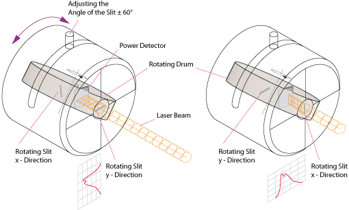
Internal to the BP209 series measurement heads is a rotating drum, whose axis of rotation is adjusted using a manual knob. Slits in the drum are scanned across the X and the Y axes of the beam as the drum rotates, and transmitted intensity is detected by an integrated photodetector.
Click to Enlarge
These maximum and minimum beam power limits are provided as functions of 1/e2 beam diameter for knife-edge and scanning-slit measurements and may not apply to measurements of total power. To prevent thermal damage to the measurement head, do not operate for longer than 5 s with input powers exceeding 1 W.
Thorlabs' Beam Software
Thorlabs' Beam software, which was developed to control and acquire measurements using our beam profilers and related M2 measurement systems, can be downloaded from the Software tab. The software includes a GUI and enables detailed control over the scan and measurement settings, including selecting the active slit pair, scanning mode, gain, averaging mode, and scan rate. The configuration and appearance of the displayed windows, which include X Profile, Y Profile, 2D Reconstruction, 3D Profile, Position vs. Time, Power vs. Time, and Calculation Results, can be adjusted as desired. The software enables M2 beam quality and convergence/divergence measurements to be made and also includes tools to assist with the task of overlapping two different laser beams. The user can select which measurement and calculation results to save to a file, and data accquired during long-term measurements can be sequentially saved. For an introduction to the software and representative screenshots, please see the User Interface tab. For detailed information describing the software's functionality, please see the manual.
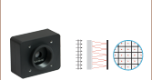
Perform Measurements with 5 µm or 25 µm Slits
The diagram to the right illustrates the configuration of the measurement head, which includes an input aperture and a rotating drum with slits in it. The beam enters the Ø9 mm input aperture perpendicular to the front plane of the measurement head and is incident on the rotating drum. The slits in the drum are spaced at intervals, and each slit spans the full width of the input aperture. There are two pairs of slits in the drum, and each pair includes one oriented at +45° with respect to the axis of rotation and the other oriented at -45°. Both slits in one pair are 5 µm wide, while those in the other pair are 25 µm wide. Including two slit width options in each measurement head and offering two operating modes enables beams with an extended range of diameters and powers to be profiled.
If the beam diameter is equal to or less than 20 µm, use the 25 µm slits and operate in Knife-Edge mode. Beams with diameters as small as 2.5 µm can be measured using this approach.
The Scanning-Slit mode can be used to measure beams with diameters between 20 µm and 9 mm. As a general rule, choose slits with widths at least four times smaller than the beam diameter to make the measurement. When this condition is met by both slit widths, the choice of scanning slit pair is influenced by the beam power and application requirements.
Measure Beams with a Wide Range of Powers
The maximum and minimum beam powers accommodated by the scanning-slit beam profilers are shown as function of the 1/e2 beam diameter in the plot at the right. The vertical black line at 20 µm marks the beam diameter at which it is necessary to switch between knife-edge and scanning-slit operating modes. In scanning-slit mode, the maximum beam power limits correspond to operation with the 5 µm slits. By transmitting a smaller portion of the beam than the 25 µm slits, using the 5 µm slits allows beams with higher power to be measured. The minimum beam power limits were determined in scanning-slit mode using the 5 µm slits for beams with diameters between approximately 20 µm and 100 µm, while the 25 µm slits were used for beams with larger diameters. Switching between the slits when the beam diameter exceeds 100 µm maximizes the amount of beam power reaching the photodetector while also maintaining an adequate ratio between slit width and beam size.
As discussed below, reduced maximum and/or increased minimum beam power limits may apply when the beam profiler is used to measure total power (see below). If the Total Power measurement falls outside of the applicable limits, an error message will be displayed in the status box in the software GUI. However, beam shape measurements using the slits can still be made, assuming the power transmitted by the slits falls within the limits plotted in the diagram.
Acquire Total Power Measurements (Power Meter Readings)
In addition to the two pairs of slits, the rotating drum contains an aperture fitted with a neutral density (ND) filter. Once per rotation, the full beam passes through this aperture, and its attenuated total intensity is measured by the photodetector. This Total Power measurement is used as a reference value for the beam profile measurements, and it can also be measured and plotted with respect to time in a GUI window. The Total Power measurement is corrected using the typical wavelength-dependent responsivity, but it is not a calibrated value. To obtain absolute optical power measurements, the user can use the software to record a calibration measurement at the wavelength of interest.
The ranges of maximum and minimum beam powers for which Total Power measurements can be acquired may not reach the limits plotted above. The limits in the graph were determined for knife-edge and scanning-slit mode operation. Scanning-slit mode transmits a fraction of the beam power to the photodetector, and during knife-edge mode the un-attenuated, ≤Ø20 µm, full beam is transmitted to the photodetector. The power in the attenuated full beam that reaches the photodetector during Total Power measurements may need to fall within reduced maximum and/or increased minimum limits than the beam powers accommodated when operating with the slits.
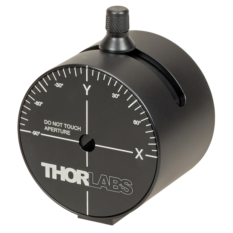
Click to Enlarge
The laser-engravings on the front face show the orientation of the X and Y axes when the knob is vertical and can be used to estimate the axes' orientation when the knob is rotated.
Choose the X and Y Scan Axes' Orientation
The knob at the top of the measurement head, which is shown in the image at right, is used to manually adjust the drum’s axis of rotation by ±60°. Adjusting the drum’s axis of rotation changes the orientation of the X and Y scan axes with respect to the beam cross section. This allows the beam profile to be measured with the scan axes defined as desired, and it enables a series of measurements to be acquired in which the orientation of the scan axes are different in each. The drum is located internally to the measurement head, and rotating the knob does not rotate the measurement head.
This functionality is of particular importance when the input beam has an elliptical cross section, as the scan axes must be aligned with the major and minor axes of a given beam in order to measure the real ellipticity. To achieve the most accurate alignment for an ellipticity measurement, rotate the knob while observing the X and Y intensity profiles plotted in the software. When the profile width in one axis is a minimum and the other is a maximum, the rotation angle is optimal.
Measure the Beam Profile of Pulsed Laser Beams
The BP209 series can be used to measure the beam profiles of pulsed laser beams with repetition rates greater than or equal to 10 Hz; however, Thorlabs' camera beam profilers are a better choice for applications that require single-shot measurements.
There is no difference between analyzing a CW signal and a pulsed signal when the pulse repetition rate is high and the duration is short, as is the case with a femtosecond laser with 100 MHz repetition rates and pulse durations lower than 100 fs. This is due to the limited bandwidth of the photodiode’s current amplifier, which cannot resolve the individual pulses and instead effectively averages the input pulse train to produce a CW signal.
When pulse rates are lower, on the order of 50 kHz or less, configure the Scan Rate setting in the software to achieve optimal measurements. As the scan rate can be set between 1.5 Hz and 20 Hz, it is frequently not possible to set the scan rate to be as fast as the pulse rate. Set the scan rate so that an integer multiple of the scan rate is slightly different than the pulse rate. Then, perform the measurement with the Hold Maximum function enabled. A set of scans are performed, and the software accumulates and averages the measured peak intensities in the scan set. When the pulse rate is fast enough for more than one pulse to be measured during a single scan, the software will accumulate and average the peak intensities of all the measured pulse segments. The reported beam profile is the final average of the set of measurements. Setting the integer multiple of the scan rate to differ slightly from the pulse rate ensures that each scan measures a different portion of the beam profile; the set of scans should include measurements of all segments of the beam profile.
Main Window

Click to Enlarge
The main window of the GUI includes the menu bar, tool bar, status bar, and a frame where several windows can be displayed. This screenshot shows several panels: Beam Settings, Calculation Results, 2D Reconstruction, and 3D Profile. The Beam Settings Panel displays all important information in a single location; this panel can be unpinned from the main window and moved to a second location, such as another monitor.
Thorlabs Beam Software for the BP209 Beam Profilers
- GUI with Adjustable Layout: Windows with Different Measurement Results
can be Rearranged and Resized within the Workspace - 2D and 3D Views of the Beam Profile
- Selectable Overlays such as Peak, Centroid, and Cut Profiles
- 3D View is Fully Rotatable
- M² and Divergence Measurements Compliant with ISO 11146
- Data Export:
- Results can be Exported from Windows in Different Formats
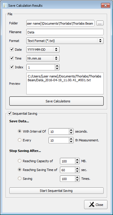
- Sequential Saving of Long Term Test Data
- Pass/Fail Tests with Customizable, Lockable and Saveable Pass/Fail Parameters
- Power Correction Available for Absolute Power Measurements
- Supports TSP01 for Temperature Logging During Long-Term Measurements
Thorlabs' Scanning Slit Beam Profilers, Camera Beam Profilers, and M² Measurement Systems all use the Thorlabs Beam software package. The screenshots below highlight key features and measurement modes that can be used with our scanning slit beam profilers, including 2D reconstructions of the beam profile and measurements of the beam stability and position. If an M² Extension Set (available below) is added to the system, the software also enables M² and beam divergence measurements.
The latest version of the Beam software package can be downloaded from the Software tab.
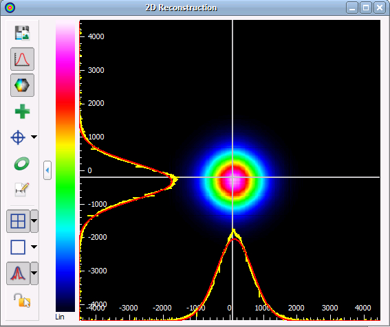
2D Reconstruction of the Beam Profile
Click to Enlarge
Slit beam profilers only measure two real orthogonal cross sections of the beam (i.e., the beam profile in X and Y). Assuming a Gaussian-like beam profile, the Beam software package can create a 2D reconstruction of the beam profile from the two cross sections, seen in the screenshot above. Buttons along the side allow users to save the image, show or hide the x and y scales, mark the centroid or peak position, and display an approximated Beam Ellipse superimposed on the image.
Calculation Results
Beam Stability

Click to Enlarge
The Beam Stability Window allows the stability versus time to be recorded and viewed. Display options include the Centroid Positions, Latest Plotted Centroid, Rolling Centroid Positions, Reference Positions, and Smallest Enclosing Circle.
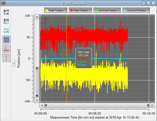
Plot Centroid and Peak Positions
Click to Enlarge
The positions of the X and Y peak and X and Y centroid positions can be displayed as a function of time in this window.
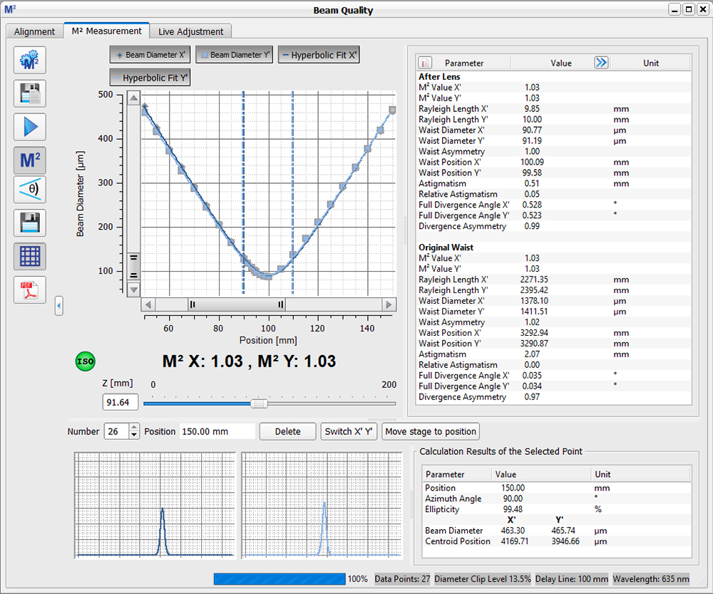
M2 Measurements
Click to Enlarge
The beam diameter and location of the beam waist are shown after an M² analysis has been performed. Note: This functionality is only enabled when using a beam profiler with one of the M² systems.
Convergence / Divergence Measurements
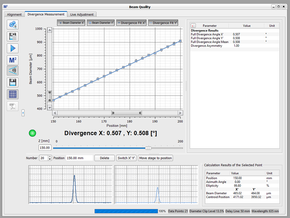
Click to Enlarge
The divergence of the beam is shown after an M² analysis has been performed. Note: This functionality is only enabled when using a beam profiler with one of the M² systems.
Software Packages for Thorlabs' Beam Profilers
The Beam software package can be downloaded by clicking on the Software button below. Please refer to the manual's programming references for interfacing with our beam profilers using LabVIEW™, C, Visual C#, and Python.
| System Requirements | ||
|---|---|---|
| Operating System | Windows® 8.1 (32 Bit or 64 Bit), 10 (32 Bit or 64 Bit), or 11 (for Beam Version 9.0 or Higher) |
|
| Connectivity | Scanning-Slit | USB 2.0 High Speed Port |
| Camera | USB 3.0 High Speed Port | |
| Monitor Resolution | 1024 x 758 Pixel (Min), ≥16 Bit Color Depth | |
| Processor (CPU) | Minimum | ≥3.0 GHz Intel Core (i5 or Higher)a |
| Recommended | Intel Core 2 i5 or AMD Ryzen 5 (3.0 GHz Min) | |
| Memory (RAM) | Minimum | 4.0 GB RAM |
| Recommended | 8.0 GB RAM | |
| Graphics Adapter | Required | OpenGL (Specification GLX 1.3 Up) |
| Minimum | Radeon: X100 Series ≥X850, X1000 Series ≥X1600, HD Series ≥2400; Geforce: 7 Series ≥7600, 8 Series ≥ 8500, 9 Series ≥9600; Quadro: FX Series ≥FX770M |
|
| Recommended | Radeon: HD Series ≥7000; Geforce: GTX Series ≥500; |
|
| Hard Drive | Minimum | 2 GB of Available Disk Space |
Features
- Settings Panel Displays All Important Parameters in a Central Location
- Customizable Calculation Results
- Measured Parameters can be Individually Hidden
- Adjustable Row Heights
- Enhanced Beam Stability Window Measures and Displays the
Smallest Enclosing Circle Around the Centroid Point Cloud
- Alignment Wizard to Aid in Correctly Aligning the M2MS M2 Measurement Systems
- Language Settings of English, German, or Chinese
Software
Version 9.1.5787.615 (February 19, 2024)
Standard full version of software package for 32-bit and 64-bit Windows with driver and graphical user interface for operating the device in standard applications.

Firmware Update for Scanning Slit Beam Profilers
Below is a link to a firmware update for Thorlabs scanning slit beam profilers to correct an error regarding hardware and firmware compatibility.
Firmware Update
Version 1.3 (September 29, 2020)
Click on the link below to download the latest firmware. The link includes instructions for installing the firmware update and necessary drivers.

Each Beam Profiler Comes with the Following Parts:
- BP209 Series Beam Profiler Head with Dust Cover
- High-Speed USB 2.0 A to Mini-B Connection Cable, 3.0 m
- Quick Start Guide
| Posted Comments: | |
Yihuan SHI
(posted 2024-03-09 10:14:37.937) 你好,
我们的激光波长为2790nm,请问你们这款BP209-IR2/M能测光斑吗?
祝好!!!! dpossin
(posted 2024-03-11 05:09:57.0) Dear Yihuan Shi,
Thank you for your feedback. I checked the responsivity of the diode used in BP209-IR2. Unfortunately the responsivity is not sufficient to still perform measurements @ 1790nm. I am reaching out to you to discuss this in more detail. Yao Jiali
(posted 2024-02-04 14:43:41.35) Hello, We used BP209-VIS/M and M2MS to measure the beam characteristics of the laser pulse focusing spot (Laser: 532nm,100Hz, 10ns). We would like to ask the following two questions:
1. Can BP209-VIS/M synchronize with the frequency of the laser through external trigger mode?
2. What is the range of beam fluence of pulsed laser that BP209-VIS/M can tolerate?Because when I keep increasing the laser fluence, it always indicates that the energy is low.
Thanks. dpossin
(posted 2024-02-07 08:59:15.0) Dear Yao,
Thank you for your feedback.
1.) The BP209-VIS does not provide an external trigger input. However pulsed lasers can be measured through the max hold function. There the software accumulates the peak intensities over a number of subsequent pulses leading to an averaged profile. Additionally the bandwidth needs to be adapted to the pulses and beam diameter.
2.) The max beam power is given for CW sources only. As a rule of thumb I would recommend to set the gain to max and attenuate the laser such that peak power is just below the max cw power we give according to the beam diameter. If there is no signal, the laser power should be gradually increased until a signal can be seen. ByeongHak Ha
(posted 2023-12-27 07:11:05.73) I purchased this beam profiler for 1543 nm laser (5 ns, 0.1 Hz, 4mJ)
This beam profiler can detect this laser?
I cannot access the manual of this model
Can you send me one manual pdf?
Thanks fmortaheb
(posted 2023-12-29 07:52:40.0) Thank you very much for contacting us. I will reach out to you directly to discuss your application. Karolina Stefańska
(posted 2023-11-16 11:35:53.557) Hello,
I wanted to share an issue I encountered with the Thorlabs Beam software version 9.0. When using the camera BC106N-VIS/M, I am not able to save the 2D image of the beam. Using any format (bmp/jpg/png/tiff), all that is saved is black rectangle. The 3D image of the beam can be saved. The previous version, 8.2, works with no problems for me with all image formats, so I use that one instead.
Perhaps this is just the problem on my laptop, but maybe it is more general...
Best regards,
Karolina Stefańska GBoedecker
(posted 2023-11-17 07:22:22.0) Thank you for your feedback! This bug has been fixed in the next software version, that will soon be released on the website. I will contact you directly to send you the installer. Andrew Chew
(posted 2023-09-06 19:12:29.323) Hi, are there 64bit versions of the LabView VIs/drivers? The 64bit LabView I have doesn't function with 32bit drivers. Thanks GBoedecker
(posted 2023-09-08 09:17:40.0) Thank you for your feedback! I tested the Labview VIs and they were working fine. I will contact you directly for further assistance. Conner Phillips
(posted 2023-09-01 11:45:15.24) Greetings,
Does the Extended InGaAs detector have a non-zero response below 800nm? The nomina is 900nm but the graph shows it going down to about 800nm, but can it be pushed even lower to say 650nm at the cost of SNR/integration time? dpossin
(posted 2023-09-06 05:50:45.0) Dear Conner,
Thank you for your feedback. In general goes on the expense of SNR, thats right. I´ll check that internally and get back to you directly via mail. Ryoichi Shibayama
(posted 2023-07-27 09:59:52.797) 同製品を使用させて頂いております。
20um以下のスポット光を測定したいと考えております。
説明書ではナイフエッジモードの使用が推奨されていると思うのですが、ナイフエッジモードでは Base Line Modeをマニュアルに設定するよう記載があります(英語取説 p75)。マニュアル設定にした場合、x/yスリットごとの補正値はどのように決める必要がありますでしょうか?
スポット光の構成
[波長905nm, CW光源, 光量250uW程度] hkarpenko
(posted 2023-07-31 04:58:26.0) Dear customer,
thank you for your feedback.
Indeed, it is recommended to use the knife edge mode to measure small beams <20µm and the baseline correction has to be adjusted, if it is not set correctly. In the software you can see the baseline in the X and Y profile. According to that you can adjust the baseline correction. I will contact you directly to discuss this further with you. Siobhan Ellzey
(posted 2023-07-21 05:51:48.277) Dear thorlabs.com owner, Thanks for the well-presented post! dpossin
(posted 2023-07-24 09:46:46.0) Dear Siobhan,
Thank you for your positive Feedback! user
(posted 2023-07-14 15:43:17.383) Hello, we are trying to create a program in python to control the BP209IR1. The goal is to collect beam data while scanning the beam (and beam profiler) across a preset area using motorized stages. The issue is that when attempting to build on the provided example code, specifically to use the provided functions get_slit_beam_width and get_slit_gaussian_fit, we are getting the error "Name Error: b'The given session or object reference is invalid." Everything was set up according to the manual and we are unable to find the cause of the error with the available resources. Please contact and thank you in advance for any additional assistance. GBoedecker
(posted 2023-07-19 04:51:04.0) Thank you for your feedback! I will contact you directly for detailed troubleshooting. jiayu wang
(posted 2023-06-29 12:10:17.613) There is no immediate indication of the changing beam as to stay in default mode of beam shape when used in the way of USB connection. This is a sudden change cause of
the previous use was normal. dpossin
(posted 2023-07-04 06:32:13.0) Dear Jiayu,
Thank you for your feedback. I am reaching out to you in order to provide further insights. 青向 许
(posted 2023-03-28 20:11:31.247) 公制与英制有啥区别 user
(posted 2023-03-12 21:37:09.133) Hello,
We are trying to use the BP209-VIS/M to track the location of one continuous wave laser beam as it is displaced laterally over a small distance (~several microns). We notice that the calculated centroid and peak positions of the beam fluctuate too much to take the displacement measurement, and are wondering if this fluctuation is intrinsic to the beam profiler. Furthermore, we noticed that when we displace the beam quickly, the calculated positions do not seem to update as expected, even though the image in the 2D reconstruction has moved by tens of microns. We'd greatly appreciate any insight on these issues! hkarpenko
(posted 2023-03-15 11:33:33.0) Dear customer,
thank you for your feedback. I will contact you directly to discuss this in more detail with you. Jeffry Pendergrass
(posted 2023-02-23 14:51:01.227) Hi thorlabs.com owner, You always provide clear explanations and step-by-step instructions. wskopalik
(posted 2023-02-24 05:37:46.0) Thank you very much for your friendly feedback!
We are happy that you like our website and that the explanations and instructions are helpful for you. Lalith Kumara
(posted 2023-02-21 02:06:19.127) Hi, I need to know the working distance from the beam profiler head,.. do we consider the inside sensor distance in 5 ~ 9mm. hkarpenko
(posted 2023-02-22 08:01:17.0) Dear customer,
thank you very much for your feedback.
If I understood it correctly, you are looking for the distance of the photodiode to the scanning slit/focusing lens. This is shown in the manual chapter 11.8. I will contact you directly to discuss this more detailed with you. Anlan Shen
(posted 2023-02-12 11:14:12.373) Hi, I was wondering if this beam profiler model is suitable for the following beam: wavelength: 1064nm, pulse duration: 10ps, repetition rate: 200kHz, spot size: 200um, power: 60mw? Thanks in advance. hkarpenko
(posted 2023-02-13 10:21:22.0) Dear customer,
thank you for your feedback. Unfortunately we did not test our beam profiler with pulsed lasers regarding the damage threshold, we can only give you an approach on how to savely use the beam profiler. I will contact you directly to discuss this further with you. Ana Torrento
(posted 2023-01-27 11:27:34.24) Hello,
I have a beam profiler model BP109-IR. I can perfectly run it with the Thorlabs Beam software.
However, I would like to drive it from a Linux PC (OS Linux Mint 20) using a Python script.
Would you have a TLBP2 driver compatible with this configuration?
Thanks a lot in advance.
Best Regards. hkarpenko
(posted 2023-01-27 10:52:57.0) Dear customer,
thank you very much for your feedback. I will contact you directly to discuss this issue further with you. ys wang
(posted 2022-12-23 17:38:39.167) Hi, I have a BP209IR-M beam profiler, and I want to get some measurement result(such as power, beam width, beam picture) through my own c++ program just as the GUI program you provided.
I found a c sample program and programing manuel about TLBP2 interface, but the logic is hard to understand, can I only get one slit measurement once? If so, how can I get the whole beam?
Best regards. GBoedecker
(posted 2023-01-04 11:52:23.0) Thank you for your feedback! The C example takes ten measurements and outputs the peak position and the centroid position of each. If you want to get a 2D reconstruction, you have to calculate for each point:
Amplitude (x,y) = PowerIntensity_X(x) * PowerIntensity_Y(y) * GaussianFitIntensity_X(x) * GaussianFitIntensity_Y(y). user
(posted 2022-12-14 10:30:44.377) Hi,
we are having a problem with our slit beam profiler:
a round beam (single mode fibre output) is measured (gauss width) to be elliptical when using the 5 um slits whereas it is round when using the 25 um slits. Power and beam size are adequate (10 mW, e.g. 700 um beam width). With the 5 um slits the beam is 5 % smaller in the one direction and 5 % bigger in the other compared to the 25 um slits. roating the beam profiler does not change the measurement.
Best regards wskopalik
(posted 2022-12-15 04:41:51.0) Thank you for your feedback!
If rotating the beam profiler does not change the elliptical beam shape of the measured profile and the 25 µm slits show the expected round beam, then there is most likely an issue with the 5 µm slits.
I will contact you directly so we can arrange an RMA for inspection and repair. Carlos Perez
(posted 2022-12-06 11:40:18.013) Hello,
What is the distance between the entrance of the beam profiler and the detector?
Regards,
Carlos Perez wskopalik
(posted 2022-12-07 03:21:46.0) Thank you very much for your feedback!
The distance between the front surface of the housing and the photodiode is 7.58 mm on the BP209-VIS(/M). The slits are a bit recessed inside the housing, so from the slits to the photodiode the distance is only 5.51 mm.
I will contact you directly to provide further assistance. 叶 先生
(posted 2022-08-05 16:43:43.023) 请问,这款可以用来测量脉冲激光器出射的光斑吗(脉冲能量300mJ、脉宽7ns、波长1064nm、重复频率30Hz)。谢谢 user
(posted 2022-07-28 10:35:55.45) Dear Thorlabs team,
I have a BC106-UV beam profiler and it works fine with the Thorlabs Beam software. However, I would like to be able to collect data from Matlab. As far as I understand, it can be done using .NET interface. I tried to write a wrapper, but I got stuck.
Could you please provide me with a Matlab code for some basic functionality of the camera? By basic I mean connect, take a picture (and send it to Matlab), correct exposure (or switch on an autoexposure) and disconnect.
Thank you in advance. dpossin
(posted 2022-08-02 04:28:16.0) Dear customer,
Thank you for your feedback. I am reaching out to you directly in order to discuss this in detail. dpossin
(posted 2022-08-02 04:28:16.0) Dear customer,
Thank you for your feedback. I am reaching out to you directly in order to discuss this in detail. haison Chen
(posted 2022-07-11 18:18:27.96) I want to test a lens beam at 2mm distance ,is the result right if I put the lens at the front of slit and distance 2mm? hkarpenko
(posted 2022-07-14 08:57:46.0) Dear Haison Chen,
thank you for your feedback.
I contact you directly to elaborate this issue with you. user
(posted 2022-07-06 07:00:35.67) Hi, is there a version of the Thorlabs Beam software for Ubuntu (20.04) available? GBoedecker
(posted 2022-07-11 12:28:29.0) Thank you for your feedback! We do not have a version of the Beam software for Ubuntu 20.04. I will contact you directly to discuss possible solutions. 成诚 刘
(posted 2022-06-15 18:17:35.88) I have a BP109-IR. After using the BP109 firmware downloaded from the website to update the software yesterday, I cannot connect to the computer, and the BP109 device cannot operate normally after powering on. I would like to ask how to flash the BP-109 software back to the original firmware? Currently unable to find BP109 related firmware information on the official website, looking forward to your reply fmortaheb
(posted 2022-06-28 10:43:31.0) Thank you for contacting us. I will contact you directly to discuss this issue and possible solutions. user
(posted 2022-06-06 16:14:03.143) Dear Sir or Madam,
I have a similar problem than the one presented in a previous feedback:
"""
user (posted 2021-03-10 13:23:31.843)
Hi, We are having a problem with our device. the program (Thorlabs Bean 7.0) does not recognize the device suddenly (before 3 days ago, it was properly works). both Refresh the Device List and Refresh Stage List has no effect. When connect the device with laptop, the RDY LED is blinking in green. The manual say that it need to update the firmware, but the Firmware updater 1.3 does not recognize device, and un-active left window. I also checked it with my desktop, which installed the program from the beginning, following the manual. At that time, the RDY LED lights up green, no blinking. But it still not recognize in the program (Thorlabs Bean 7.0). In Firmware updater 1.3, it is recognized (activate left status window), but there are error at update progress in 30% with error message: The data can not be transferred to the device. Please let me know the troubleshoot in this case.
"""
Could we get in touch please?
Thanks fmortaheb
(posted 2022-06-09 04:55:56.0) Thank you very much for contacting us! I will reach out to you directly to troubleshoot. Jens Kießling
(posted 2022-05-06 06:54:00.993) Dear Thorlabs team,
we have a BC106-VIS, which is only specified down to 350 nm. We need to measure down to 300 nm and the beam profiler is working well, but the software blocks setting the analysis wavelength to below 350 nm. Is there any option to remove this software restriction?
many thanks in advance
Jens dpossin
(posted 2022-05-10 04:17:13.0) Dear Jens,
Thank you for your feedback. I am reaching out to you directly to discuss your application. suhong cai
(posted 2022-01-27 15:48:11.597) 请问怎么联系技术支持 Monique Wiertsema
(posted 2021-12-23 08:46:21.233) Hi,
Earlier I could connect the BP209IR to my PC, and also the software worked well. However, without changing anything, now I cannot change anything in the beam settings panel, because then the program fails and shuts down automatically. I do not know why. Previously, I could change the wavelength and scan rate without any problem.
I already uninstalled the software, and re-installed it from your website. The beam profiler is listed in the device manager NI-VISA USB Device, having the name "Thorlabs BP2 Multi-Slit Beam Profiler".
How can i fix this issue? Thank you for any help wskopalik
(posted 2021-12-29 09:08:11.0) Thank you for contacting us!
It is unfortunately hard to tell what causes this issue without further troubleshooting. I will therefore contact you directly so we can find a solution for this issue. Rodrigo Vicencio
(posted 2021-12-15 15:39:45.417) Hi, I have three beam profilers (visible range) and we are quite curious about the codification of images. We need to know more information about the B&W images, which are exported in linear scale. Do they represent the amplitude or the intensity of the light field? We have this doubt due to an analysis we did which show that they could represent the amplitude of the electric field instead of intensity. A clarification of this is very welcome for us.
Best regards, Rodrigo fmortaheb
(posted 2021-12-23 08:57:47.0) Dear Rodrigo, thank you for your feedback. I will contact you directly to discuss your questions in more detail. Sudhir Ingle
(posted 2021-06-12 13:47:14.003) Hello,
Do you have a patent publication number for this product - Scanning-Slit Optical Beam Profiler?
Can you please send us the number?
Thanks and Regards
Sudhir mdiekmann
(posted 2021-06-17 02:51:43.0) Thank you for contacting us. We do not have a patent for this device. user
(posted 2021-03-24 05:23:13.72) Hi, I would like to use the BP209-VIS for a highly non-Gaussian beam with a diameter of roughly 5micron. Is it possible to use the beam profiler for such an application and extract the profile for fitting and processing externally? mdiekmann
(posted 2021-04-01 11:03:01.0) Thank you for contacting us! The BP209-series is best suited for Gaussian or near Gaussian beams, most importantly, the beam needs to symmetric. As you opted not to be contacted, please reach out at europe@thorlabs.com to discuss your application in detail. Hoseong Song
(posted 2021-03-17 11:09:18.66) I am using your beam profiler.
After firmware update(version Thorlabs firmware updater 1.3), No Beam Profiler recognized.
Before firmware update, the device worked normally.
What do I need to do to solve the problem? MKiess
(posted 2021-03-23 07:17:46.0) Dear Hoseong Song, thank you very much for your inquiry. Possibly the data was not written correctly to the EPROM during the update.
For the firmware update, please use the Firmware Updater, which you can find under the following link:
https://www.thorlabs.de/software_pages/ViewSoftwarePage.cfm?Code=Beam&viewtab=1
In the "Read me" file available for download under this link, there is a step-by-step manual on how to proceed so that no errors occur. user
(posted 2021-03-10 16:37:20.707) Hello, I am the same person as the person who asked the question a below (posted 2021-03-10 13:23:31.843). There are few updates.
First, I updated the firmware. When I changed the USB cable, it proceeded normally, and I updated it to the latest version, version 0.60.
The problem is still not recognized by the Program (Thorlabs Beam 7.0).
Also, there was a loud noise on device when updating the firmware.
Please let me know the troubleshoot in this case. MKiess
(posted 2021-03-15 10:40:13.0) Thank you very much for your inquiry. The current firmware is the version 1.3. The latest firmware version for our Beam Profiler, can be found under the follwoing link: https://www.thorlabs.de/software_pages/ViewSoftwarePage.cfm?Code=Beam&viewtab=1.
For the best performance, if you want to use the Beam Profiler with the latest Beam software version, I recommend to use the latest firmware version. user
(posted 2021-03-10 13:23:31.843) Hi, We are having a problem with our device. the program (Thorlabs Bean 7.0) does not recognize the device suddenly (before 3 days ago, it was properly works). both Refresh the Device List and Refresh Stage List has no effect.
When connect the device with laptop, the RDY LED is blinking in green. The manual say that it need to update the firmware, but the Firmware updater 1.3 does not recognize device, and un-active left window.
I also checked it with my desktop, which installed the program from the beginning, following the manual. At that time, the RDY LED lights up green, no blinking. But it still not recognize in the program (Thorlabs Bean 7.0). In Firmware updater 1.3, it is recognized (activate left status window), but there are error at update progress in 30% with error message: The data can not be transferred to the device.
Please let me know the troubleshoot in this case. MKiess
(posted 2021-03-15 10:46:44.0) Thank you very much for the inquiry. I have contacted you directly to discuss the details and to find a solution together with you. Bénédicte Gaudron
(posted 2021-03-03 00:21:43.933) Bonjour,
J‘aimerai avoir un devis pour cet analyseur de faisceau Laser. Je vous en remercie par avance. Cordialement. B. Gaudron soswald
(posted 2021-03-04 06:49:11.0) Dear Bénédicte,
thank you for your enquiry. Our sales team will reach out to you directly with the requested quotation. Jiawei Chen
(posted 2020-11-19 13:16:33.7) LabVIEW Examples soswald
(posted 2020-11-19 08:00:11.0) Dear Jiawei,
thank you for your feedback. You can find a step-by-step guide on how to create a LabView VI for our beam profilers in the programming references:
https://www.thorlabs.de/software_pages/ViewSoftwarePage.cfm?Code=Beam&viewtab=2 ------>
Programming Reference ------>
Camera and Scanning-Slit Beam Profilers
I have reached out to you directly in case you need further assistance. OHOSUNG KWON
(posted 2020-11-09 03:58:07.187) To connect to PC, I have a connection problem.
I'm using NI-VISA 20.0.
Is that problem? MKiess
(posted 2020-11-09 11:15:24.0) Thank you very much for your inquiry.
This is no problem. What you need in additional software is National Instruments® VISA Runtime Engine 5.2 or higher. Version 5.4 is Included in the Software Package. Kevan Bell
(posted 2020-10-19 11:54:20.093) Hello,
I have a question regarding your BP209-VIS scanning slit profiler. How well does it operate with nanosecond and picosecond pulsed lasers? You mention a minimum rep rate, does it still operate with these pulsewidths in the 50 kHz+ rep. rate regime?
Kevan MKiess
(posted 2020-10-20 10:17:10.0) Dear Kevan, thank you very much for your inquiry. In general, camera beam profilers are better suited for measuring pulsed laser sources, but you can also use the BP209 for nanosecond pulses at fast repetition rates.
At 50kHz, the scan rates have to be adjusted in the software to get the best results. To do this, you have to set the scan rate so that an integer multiple of the scan rate is slightly different than the pulse rate. Because, setting the integer multiple of the scan rate to differ slightly from the pulse rate ensures that each scan measures a different portion of the beam profile; the set of scans should include measurements of all segments of the beam profile. user
(posted 2020-10-09 14:38:06.287) Hello, I am using the Thorlabs Beam 7.0 software to measure the 2-D profile of our laser spot. When selecting "Profile X" or "Profile Y" to show the measured intensity profiles along the axes, I found the software only shows the profiles along the peak position. Is it possible to define which line to show (ie. centroid position) by users? nreusch
(posted 2020-10-13 10:39:49.0) Thank you for your feedback. While the x and y profile data are displayed in the windows named “Profile X” and “Profile Y”, the centroid position can be tracked in the window named “Plot Positions”. The plot positions window can be activated next to the x and y profile windows in the software menu bar and you can choose to show the centroid positions as well as the peak positions for x and y respectively. mk mk
(posted 2020-08-04 07:32:05.837) Hi,
could you please indicate the damage thresholds for ultrashort pulsed lasers?
Let's say we have:
-50 fs
-50 um beam radius
-100 MHz
-2400 nm cental wavelength
Then what would be the max. average power that can be incident on the extended beam profiler?
Thank you for your help
Best
Maciej dpossin
(posted 2020-08-04 09:54:50.0) Dear Maciej,
Thank you for your feedback. At an beam diameter of 50µm you can apply a maximum average power of 0.01 mW. See the corresponding graph here: https://www.thorlabs.com/newgrouppage9.cfm?objectgroup_id=804&Tabname=Specs. I am reaching out to you in order to provide further help. Xiaoxian Guo
(posted 2019-11-29 12:53:21.657) Hello,
Is it possible to allow external software to obtain data directly from the beam profiler for further data processing ? MKiess
(posted 2019-12-02 09:05:58.0) This is a response from Michael at Thorlabs. Thank you for the inquiry. You can save the calculations in *.txt, *.csv or *.xls format in the corresponding beam software available for download on our webpage.
Furthermore it is possible to write your own program for data acquisition. For this purpose we provide the instrument drivers, some tools for programming, as well as programmer references for the programming languages LabVIEW, C++, C# and Visual Basic, included with the software download.
I've contacted you directly for further assistance user
(posted 2019-10-29 23:04:16.937) On the manual AD Saturation mean Displays the current saturation of the Beam Profiler's AD converter.
I want to ask what is current mean? dpossin
(posted 2019-11-01 06:02:33.0) Dear Customer,
Thank you for your feedback. Current in this context does not mean a physical value. For instance you could also use an expression like "present". david.grant
(posted 2019-03-05 10:45:46.107) I am intersted in a beam profiler at focus for a 7um spot at 1340nm and 0.5-10kHz repetition rate. Could you give advice whether this would be suitable. MKiess
(posted 2019-03-12 04:44:40.0) This is a response from Michael at Thorlabs. Thank you for the inquiry. With the BP209 series the beam profile of a beam with a diameter of 7µm and a wavelength of 1340nm can be measured. Pulsed laser beams can be measured at repetition rates greater than 10Hz. If the pulse frequencies are in the range of 50 kHz and less, the beam profiler does not analyze the beam as a CW signal, as is the case with very fast frequencies. Therefore, the scan rate settings must be configured in the software to achieve optimal measurements. This is done by setting the sampling rate so that an integer multiple of the sampling rate is slightly different from the pulse rate. When the Hold Maximum function is enabled, series of scans are performed and the software accumulates and averages the measured peak intensities in the scan set.
I will contact you directly to discuss detailed software settings and whether the better choice for this application would be a Thorlabs' Camera Beam Profiler. e.jaegle
(posted 2017-10-06 08:50:37.043) I'm confused about the plane of measurement - the drawing in the manual says that it is located 2.1mm inside the profiler, but when we compare the distance at which our focused beam has its minimum diameter as measured by the profiler and by other means there seems to be a 2mm offset, as if the plane of measurement was actually at the profiler surface. swick
(posted 2017-10-11 03:43:26.0) This is a response from Sebastian at Thorlabs. Thank you for the inquiry.
The position where the rotating slit scans the beam is the measurement plane.
It is located 2.1mm behind the aperture.
I have contacted you directly for assistance. user
(posted 2017-08-09 21:30:01.457) Whenever I connect the beam profiler, everything else connected through USB automatically gets disconnected, and their softwares (including Thorlabs' very own Kinesis, which I could only think is just a joke). I thought my computer is out dated, I'm using a brand new high performance desktop, and many others in the lab are experiencing it. Thorlabs softwares are very unreliable and chat personnel not very helpful. tschalk
(posted 2017-08-10 05:58:52.0) This is a response from Thomas at Thorlabs. I am really sorry that you have experienced difficulties with our Software. I would recommend that you contact me at europe@thorlabs.com to discuss this issue in detail. I am sure that we can provide assistance in this case. dengyang
(posted 2016-11-15 16:42:35.017) Do you have a combined version of beam profiler which is able to cover wavelength range from 200nm to 1700nm? It is ok to switch the slits and detectors. swick
(posted 2016-11-16 03:11:19.0) This is a response from Sebastian at Thorlabs. Thank you very much for your feedback.
We will evaluate if we can offer a combined version with Si- and InGaAs photodiodes in the future. At the time our Scanning Slit Beam Profilers are covering operating wavelength ranges of 200 - 1100 nm (BP209-VIS) or 900 - 1700 nm (BP209-IR).
For measuring beams at 200-1700nm both the BP209-VIS and the BP209-IR have to be used. We will contact you directly to provide assistance. jari.nikkinen
(posted 2016-11-03 14:03:35.743) We bought M2-measurent system with BP209, and separately later bought BC106 for it. We are now missing the mounting adapter for BC106. How do we get one? swick
(posted 2016-11-04 04:22:57.0) This is a response from Sebastian at Thorlabs. Thank you very much for your inquiry.
I will contact you directly to provide a quotation for the BC106 mounting adapter. janis.golubeckis
(posted 2016-10-28 16:51:19.71) It appears that centroid is drifting around and it seems to be related to profilers internal vibration. Do you have a measurement stability spec? swick
(posted 2016-10-31 06:17:26.0) This is a response from Sebastian at Thorlabs. Thank you very much for your inquiry.
We do not officially specify the stability of centroid detection but we are testing each device during quality control. The stability of the centroid is related to the Clip-Level, which should be set accordingly.
I have contacted you directly for assistance and troubleshooting. milankie
(posted 2016-08-23 13:36:56.767) Can you provide the raw VISA commands for interacting with this device? swick
(posted 2016-08-24 03:51:43.0) This is a response from Sebastian at Thorlabs. Thank you very much for your inquiry.
After installing the software of the Beam-Profiler, you can find a list with detailed information for all VISA commands at folder:
C:\Program Files (x86)\IVI Foundation\VISA\WinNT\TLBP2\Manual\TLBP2
I have contacted you directly to provide further assistance. miljenko.suljic
(posted 2016-05-20 10:15:30.043) Hi, I'm interested if this product would be suitable to characterise the following beam:
Wavelength? 1060 nm; Spot size? 15-20 um; Laser power: max 1mW; Pulsed, frequency < 1 kHz; Pulse length: ~15 ns;
Thank you in advance shallwig
(posted 2016-05-23 03:16:21.0) This is a response from Stefan at Thorlabs. Thank you very much for your interest in our products. I have contacted you directly to check if your beam features a Gaußian shape and is suitable to get measured by our slit beam profilers and to discuss if a camera beam profiler would be a better option. hawthorne
(posted 2016-05-03 09:06:16.783) What is the return policy on this device if we are unable to use it for a diagnostic in our lab? shallwig
(posted 2016-05-04 03:12:04.0) This is a response from Stefan at Thorlabs. Thank you very much for your interest in our beam profilers. If the device is not suitable for your application we can take it back. I will contact you to discuss your application and check if a LOAN unit is an option before you buy the device. isabelle.riou
(posted 2016-04-20 11:08:46.15) We are having the same problem as patrick.ledingham. The device is no longer recognised by the computer and the green LED no longer lights up. Did you found a solution? shallwig
(posted 2016-04-20 07:23:09.0) This is a response from Stefan at Thorlabs. I am really sorry for the problem you have with our beam profiler. I will contact you directly to check if this can be solved remotely or if we have to take the unit back for repair. patrick.ledingham
(posted 2016-03-21 13:58:57.59) We are having a problem with our device. Computers are no longer recognising it. The green LED labelled 'RDY' no longer lights up. Before this issue, the software was throwing an error that the firmware needed to be updated. tschalk
(posted 2016-03-22 07:33:07.0) This is a response from Thomas at Thorlabs. I am really sorry that you have experienced difficulties with our device. From my point of view it sounds like the profiler is defective. I will contact you directly with more detailed information. cyj5595
(posted 2015-12-11 12:43:03.357) I found that the R6030 runtime error can be resolved by changing Microsoft IME in some computer, however, another computer cannot. For this case, please uncheck "image protect service" at windows - start - msconfig - service tab shallwig
(posted 2015-12-11 02:41:23.0) This is a response from Stefan at Thorlabs. Thank you very much for your valuable feedback . This solution hopefully also helps other customers who face this problem. hcn
(posted 2015-08-16 23:39:01.363) My device keeps showing runtime error message even after changing Microsoft IME. How to resolve it in my case shallwig
(posted 2015-08-17 09:29:53.0) This is a response from Stefan at Thorlabs. Thank you very much for your inquiry and pleas apologize the problems you face with the beam profiler software. The runtime error r6030 can occur on Japanese and Chinese operating systems when Microsoft office is installed. This error is caused by changing the input method editor (IME) after installation of MSOffice 2010. In the manual on page 126 http://www.thorlabs.de/thorcat/21400/BP209-VIS-Manual.pdf you can find a screenshot showing how to resolve this by setting the IME back to standard Microsoft IME. I will contact you directly to troubleshoot this in more detail. patrick.lu
(posted 2015-05-15 20:56:25.763) I have a question about the optical measurement plane. In your CAD drawing it is 2.1mm inside the device, but I cannot tell if that is measured from the front or rear surface. We are producing a 4 micron diameter spot size using an objective lens. The working distance is pretty small, so I would like to know if it will be possible to position the lens close enough to the device to place the focal point at the plane of beam measurement. Also, will the device work if it is not placed upright? Our beam propagation is in the upwards vertical direction, so we would have to lay the BP209 face down on some kind of fixturing to allow the beam to be captured. tschalk
(posted 2015-05-18 09:53:48.0) This is a response from Thomas at Thorlabs. Thank you very much for your inquiry. The measurement plane is located 2,1mm inside the device measured from the front surface. For beam diameters below 20µm the knife edge mode has to be used. Detailed information about that mode can be found in the manual at section 4.3.8 Knife Edge Mode. The device can also be used in a horizontal position but you have to take care that you dont affect the rotating drum in order to avoid a damage of slits. I will contact you directly with more detailed information. spreemanm
(posted 2015-04-07 10:45:46.69) Is it possible to get a trigger out signal, or real time photodetector reading for synchronization of the measurements to other events? shallwig
(posted 2015-04-13 03:23:40.0) This is a response from Stefan at Thorlabs. Thank you very much for your inquiry. At the moment it is unfortunately not possible to offer this device with a trigger output. We cannot offer a software trigger as a very precise determination of the slit position is not possible with our software. From the beam profilers housing design there is not enough space for integrating a hardware trigger. The built in encoders only have a limited accuracy in position determination thus the internal feedback circuit readjusts the rotation speed all the time. Therefore it is difficult to get out a trigger signal very precisely each time the slit crosses the beam.
We have contacted you directly to discuss your application in more detail and to check if there is a possibility to implement a trigger in the future. y.s.yong
(posted 2015-03-13 15:33:25.343) I would like to program the beam profiler to switch to knife-edge mode while scanning it along the beam propagation direction. Could you please publish the necessary Labview routine needed to get the Gaussian beam widths read-out under knife-edge mode, as well as the routine needed to switch it back to scanning-slit mode? shallwig
(posted 2015-03-16 07:56:31.0) This is a response from Stefan at Thorlabs. Thank you very much for your inquiry. With the current driver version on our homepage it is not possible to switch between knife-edge and scanning-slit method. We are working on a Beta version of a new driver where these features will be implemented. This version is supposed to go online in about 3-4 weeks. I will send you by mail a Labview example for the knife edge mode which will also allow you to create an application to switch between knife edge and scanning slit method. I will contact you directly to discuss your project in more detail. user
(posted 2015-03-02 15:07:14.1) I downloaded the ThorlabsBeam_v6.0.783.2494, try to run ThorlabsBeamviewLabviewSample.vi, but said Qtcore4.dll is missing. where to find this file? tschalk
(posted 2015-03-04 06:23:39.0) This is a response from Thomas at Thorlabs. Thank you very much for your inquiry. The Qtcore4.dll should be located in the following folder: C:\Program Files (x86)\Thorlabs\Beam - Beta. Please contact europe@thorlabs.com if you dont find it there or if you have any additional questions. user
(posted 2015-02-12 14:16:38.29) Where can I find the Labview vi for BP209-IR? tschalk
(posted 2015-02-13 04:27:44.0) This is a response from Thomas at Thorlabs. After the installation of the Beam Software you can find the LabVIEW VIs at the following location on your computer: C:\Program Files\National Instruments\LabVIEW 2012\instr.lib\TLBP2. I will contact you directly with further details. tebeech
(posted 2014-11-25 16:08:40.06) Hello, I would like to separately purchase the mounting adapters for the BP209 that come as part of the M2MS purchase. Is this possible?
Thank you,
thomas shallwig
(posted 2014-11-26 06:42:47.0) This is a response from Stefan at Thorlabs. Thank you very much for your inquiry. We will contact you directly and provide you with a quote for this part. acb
(posted 2014-11-25 09:50:25.183) The LabVIEW files does not contain an example of a M^2 measurement. I can see that Stefan from ThorLabs are working on a M^2 driver - for LabVIEW perhaps? I would very much appreciate this feature. shallwig
(posted 2014-11-25 06:13:55.0) This is a response from Stefan at Thorlabs. Thank you very much for your inquiry. We are still working on programming an M2 driver which will also include a Labview example of an M2 measurement. We will be able to provide this driver in the first quarter next year. I will contact you directly and inform you as soon as this update is available. johanna.tragardh
(posted 2014-10-08 18:11:20.103) Hi,
1) Is there example code available for the BP104 for labview? The installed files seems to be only for BP2xx (I can find the subvi:s for BP104, no problem, but not the sample code).
2) Could you consider in the next release of the software to include the possibility of plotting a time trace of the beam width along with the position, power etc. ?
Thanks! shallwig
(posted 2014-10-09 06:15:26.0) This is a response from Stefan at Thorlabs. Thank you very much for your inquiry. For the discontinued BP104 we unfortunately have no Labview example code available, only for the BP2xx series. At the moment we are programming a new M2 driver which will also have an example code for the BP1xx beam profilers.
To your second question. With our latest Beam software version (6.0) you can already plot the power, position and beam stability versus time. In one of our next versions we will also implement the possibility to plot a time trace of the beam widths.
I will contact you directly and provide you with information about when both, a new software and the M2 driver will be available. borisinstereo
(posted 2014-09-10 16:43:41.92) Please consider shipping this product with a 90-degree elbow USB connector. This reduces the depth of the instrument by a couple of inches, making it a lot easier to insert into a setup. shallwig
(posted 2014-09-11 06:14:19.0) This is a response from Stefan at Thorlabs. Thank you very much for your feedback. We will discuss internally with the responsible product engineers which connectors we could offer here. I will contact you directly to discuss the needs for you application in detail. kuw4214
(posted 2014-05-20 09:44:56.54) I need the beamprofiler for the below laser spec.
1) Current power : 200~240VAC, 50/60Hz
2) Consumption power : 2.3KVA
3) Crystal material : Nd:YAG
4) Wavelength : 532?, 1064?
5) Pulse width(Pulse Duration)
?) 532?/1064?(Q-Switched) : 5?
?) 1064?(Non-Q) : 330?
6) Output energy (Beam)
?) 532? : 50~900mJ
(50mJ ~ 200mJ?? 10mJ increment, 200mJ ~ 900mJ 25mJ increment)
?) 1064? (Normal) : 100~2000mJ
(100mJ ~ 500mJ 25mJ increment, 500mJ ~ 2000mJ 50mJ increment)
?) 1064? (Long) : 100~3200mJ
(100mJ ~ 500mJ 25mJ increment, 500mJ ~ 3200mJ 50mJ increment)
?) Laser grade : Class 4
7) OPTIC POWER
?) 532? : 900mJ
?) 1064? (Normal) : 2000mJ
?) 1064? (Long) : 3200mJ
8) PEAK POWER : 400 ?/?
9) Frequency : 1? ~ 10?
10) Spot size : 2? ~ 10?(1? increment)
Please check this inquiry and let me have the quotaiton and products information.
Best regards.
Paul Kim. tschalk
(posted 2014-05-21 09:36:39.0) This is a response from Thomas at Thorlabs. Thank you very much for your inquiry. Because of the low rep rate of your laser source a slit beam profiler is not suited for your application. We can offer a CCD camera beam profiler BC106N-VIS which is also able to determine the profile of a single pulse. Please note that damage threshold data is currently not available for our beam profilers. For use with pulsed lasers, we recommend the following procedure as a guideline for determining a safe upper limit: Set the beam profiler to the maximum integration time (i.e., set the exposure to 1 s). Slowly increase the power until your signal reaches approximately 50% of the intensity as shown in the Profile window of the Beam software package. Multiply this power by a factor of 10. This is the safe upper limit of the mean pulse power for the beam profiler. I will contact you directly to discuss your application. user
(posted 2013-11-22 15:52:26.423) I am measuring the profile of a diode laser. It has a lot of secondary lobes that are wrecking the fit. Can I threshold the fit to get a better reading? tschalk
(posted 2013-12-02 03:45:51.0) This is a response from Thomas at Thorlabs. Thank you very much for your inquiry. In this case, it could be helpful to use the Baseline Correction. It would be great if you could contact me at europe@thorlabs.com to discuss your application. xgsun
(posted 2013-07-25 09:13:00.407) I am trying to measure the beam profile of the out of a optical fiber. the waist is located ~1mm from the fiber tip. I tried to put the fiber tip as close to the drum surface as possible. But I can get to the wasit. Is the slit located behind the drum surface ~2mm? tschalk
(posted 2013-07-26 08:16:00.0) This is a response from Thomas at Thorlabs. Thank you very much for your inquiry. You can find the detailed information about the dimensions in the manual (https://www.thorlabs.de/Thorcat/21400/BP209-VIS-Manual.pdf) in section 7.2.5.2: Slit and Photodiode Position. There you can see that the slit is located 2.07mm behind the surface of the beam diameter. I will contact you with more detailed information. jvigroux
(posted 2013-02-26 04:17:00.0) A response from Julien at Thorlabs: Thank you for your inquiry. The reading values depends on the parameters setting of the beam profiler, so that based on the setting used in your program, it might be that the software will give different results. I will contact you dircetly to help with the troubleshooting. jlow
(posted 2012-10-05 09:12:00.0) Response from Jeremy at Thorlabs: The distance from front surface to the photodiode is 7.40mm for the BP104-IR and 6.90mm for the BP109-IR. The tolerance is about 0.20mm. You can also find out more about the slit and photodiode position for our BP series beam profilers in Section 7.4.5.2 of the manual. minseog
(posted 2012-10-05 06:35:40.0) I have BP104-IR and BP109-IR. In M2 measurement the the waist position is displayed as the result. But how can we know the exact focal length of the beam propagated? I think I need to know the exact Ge sensor position or distance from the front surface of the BP109-IR. Waiting for your quick reply. jlow
(posted 2012-08-16 09:16:00.0) Response from Jeremy at Thorlabs: You should be able to use the drivers with Visual Basic (VB). Unfortunately we do not offer a VB example program and we would not be able to provide support for this. You can use more than one beam profiler in the same computer but you would need to run two instances of the software (if you use our software). ux7516
(posted 2012-08-13 11:02:42.0) I want to use BP109.
I has the questions.
1) Can I use Visual Basic6?
2) Can I use two BP109 in a computer? jvigroux
(posted 2012-06-14 07:46:00.0) A response from Julien at Thorlabs: Thank you for your inquiry. There is a priori no absolute time interval within which the beam profiler necessarily needs to be calibrated. This will largely depends on the use that is made of it and the environment within which it is used. We recommend however sending the device about once year to ensure the best possible functionality. ebrud
(posted 2012-06-12 13:01:12.0) Hi, we had BP-109-IR, could you inform me as soon as possible does this device need regular factory calibration after some usage period or no? If yes, in which period does it need calibration and do you calibrate when we sent it to you? Thanks in advance. jvigroux
(posted 2012-04-27 09:44:00.0) a response from Julien at Thorlabs: Thank you for your inquiry! This problem might be related to the fact that the NI runtime engine is not installed on your computer. I will contact you to troubleshoot this issue. danielle.wuchenich
(posted 2012-04-26 18:41:06.0) Just bought a BP109-IR profiler. The Thorlabs Beam Application (4.0, Build 128, Qt 4.7.1) works fine, although the "Start NI Network Variables" option under the Control drop-down menu is greyed out. When running the included sample VI from Labview, cannot connect to the profiler. Running Labview 2009. Please advise if you need more details and how to fix Profiler/LabVIEW error. jvigroux
(posted 2012-03-20 08:06:00.0) A response form Julien at Thorlabs: This error is very surprising. I suspect that the problem is related to the higher power that is being used. I will contact you directly as some further information would be required in order to find out what the exact origin of the problem is. hbal9604
(posted 2012-03-19 20:15:15.0) Our lab has purchased the following laser beam profiler from Thorlabs:
BP104-IR
We are trying to use this item to profile a laser beam with a wavelength of 1550 nm. The unit we are using to produce the laser beam is an amplifier from NP Photonics, which enables us to output powers ranging from 40 mW to about 5 W.
I have been attempting to use the BP104-IR to perform this profiling. However it seems that the beam computer software 'crashes' when I attempt to use the BP104-IR for powers greater than 65 mW.
The profiler does work for powers below 65 mW, however if we exceed this threshold, the following error occurs:
"The Beam Profiler device has been removed. Please reconnect the Beam Profiler, refresh the device and select the device again"
I have been unable to resolve this issue by consulting the operation manual, and there fore am seeking technical support and advise to overcome this issue. Please get back to me ASAP regarding this issue
Thank you bdada
(posted 2011-12-26 09:19:00.0) Response from Buki at Thorlabs:
I am sorry to hear about the problem you experienced with the BP104-IR2 beam profiler. We will contact you to set up the return and replacement of the unit. ppa.jacquet
(posted 2011-12-22 16:24:19.0) We just bought an 104-IR2. We got a warning for too high power even without any beam reaching the profiler. The power is below 10 mW with a beam of ~1 mm diameter at around 900 nm. jvigroux
(posted 2011-12-06 12:41:00.0) A response from Julien at Thorlabs: this type of measurement is in principle possible but there will be several points to carefully consider in order to ensure the best possible measurement accuracy. For instance, you will need to ensure that the beam power is strongly reduced to avoid damage. Also, due to the large tuning range of this system, you will only be able to measure a portion of the spectral range with a given beam profiler. Finally, the fact that the laser is pulsed will tend to increase the measurement time for a given profile. We would be happy to further discuss all those points and help you in your choice of beam profiler. Please feel free to contact us any time at techsupport@thorlabs.com user
(posted 2011-12-06 10:11:16.0) Hi, we have a Ekspla NT242 pulsed laser (7ns pulse, 1kHz). Can the focus shape be measured with this scanner? jvigroux
(posted 2011-05-12 11:46:00.0) A response form Julien at Thorlabs: The slit is used as a mask and the intensity going through this mask is measured by the photodiode. The measurement results thus provides the beam profile along the two scanning axes at the position of the slit. xiaokangs
(posted 2011-05-11 13:50:25.0) Is the beam size measured at the slit position or at the photodiode? tor
(posted 2011-01-04 15:16:05.0) Response from Tor at Thorlabs to v-nr: 1) Power density of pulses is too high; this may cause damage to the slit. We recommend using wedge filters to attenuate excessive power.
2) BP10x series is not recommended for such asymmetric beam profiles; however, please be guided by the minimum width for power density reasons. v-nr
(posted 2010-12-13 16:31:05.0) 1). How should I determine the allowed input power in case of pulsed lasers? We use 1.06 µm 45-100 kHz source with 150-200 ns pulse duration, so the peak power is 50-150 times higher then the average power. The beam diameter is usually 600 µm. Should I keep the peak power below 1 W, or it is safe to use any source with average power less then 1 W ? Is it safe to refer to the profiler’s readings when analyzing the usable power level?
2). How should I use the power ranges diagram in case of extremely elliptic beam, e.g. 8:1? Which upper power limit should I take – the one that corresponds to the minimum width, or the one that corresponds to the maximum width?
Thank you in advance. n.andermahr
(posted 2010-10-25 12:58:35.0) Do you have a demo.vi for LabView customization? Thorlabs
(posted 2010-10-26 03:42:45.0) Response from Javier at Thorlabs to n.andemahr: A small example program is included in the drivers download of the BP beam profilers. You can find it in the functions palette > Intrument I/O > Instrument drivers > BP1. You can also find more information on page 88 of the manual (http://www.thorlabs.com/Thorcat/13500/13571-D02.pdf) Thorlabs
(posted 2010-09-20 17:28:05.0) Response from Javier at Thorlabs to last poster: Thank you very much for submitting your feedback. We are currently implementing correct measures to improve the performance of our slit scanning beam profilers. Please contact us at techsupport@thorlabs.com for more details. user
(posted 2010-09-20 12:12:56.0) Useful product for its price but the Rotation Mount is not firm enough. The Scanning Head can move too much inside the Rotation Mount. We have had to set our rotational position and then glue the Head in the Mount, which is not optimal but works. Otherwise values vary by too much for beams that diverge quickly. klee
(posted 2009-12-14 16:37:36.0) A response from Ken at Thorlabs to aditya.suresh: The beam profiler itself does not measure the M2 values. You should take a look at our Complete M2 Analysis Sets (M2SET-VIS or M2SET-IR) instead. You can click on the "Beam Quality Analyzer" under the Related Products above. aditya.suresh
(posted 2009-12-10 18:31:48.0) can you let us know if we can use this system to measure M2 values for beam outputs from a fibre?
Thanks,
A kenlee
(posted 2009-12-10 11:58:30.0) A response from Juergen from Thorlabs to bear020121212:
1) You ask, if rotation speed of the drum with slits is influencing the m² result? No, it should not, if the BP10x device settings were made correct. Please explain more detailed, why you are asking that.
2)No, in the SW you can observe either 2D profiles (in real time) or you can watch the virtual (calculated) 3D profile - a slit scanning beam profiler cannot deliver a genuine 3D profile, becaúse the slits are scanning the beam under +45° and -45° angle simultaneously. bear020121212
(posted 2009-12-10 10:13:51.0) Is the rotating of slit influence the measurement result of the M square factor of the laser? Could I use this beam profile to observe the 3D or 2D beam distribution simultaneously? jhartmann
(posted 2009-11-12 17:46:20.0) A response from Juergen from Thorlabs to c.j.lee:
The BP10X beam profilers are based on a rotating drum with scanning slits. The source of electrical signal is a photodiode, locate behind the slits inside the drum.
As for this, X and Y 2D profiles are real time profiles, as they represent the photodiode current vs. time. The X and Y scans can be saved, which make sense of course only for Gaussian or close to Gaussian beam profiles.
A beam profile in 3D in this case can be calculated only, its not a real picture, but just a virtual image - this is the reason why 3D profile cannot be exported as a number or array of data: There is only 1 value changing in time, and this time is formed by human eye to a consistent picture while its actually only a sequence of dots. Analogy: old CRT TV images...
"quite messy beams" is clearly NOT a suitable application for any scanning slit beam profiler (not only made by Thorlabs). We offer a camera beam profiler, where the beam profile is represented in a real 3D picture, based on a CCD camera - pixel coordinate and its intensity.
The item # is BC106-VIS or -UV. Unfortunately, there is no IR version available due to a lack of IR sensitive CCD image sensors (Si is becoming transparent above 1000nm)
So, in order to resolve your issue, Id like to ask you about details on your laser:
- type of laser
- CW or pulsed?
- wavelength
- power?
- beam diameter?
- expected beam shape?
- what beam parameters you want to characterize? c.j.lee
(posted 2009-11-12 09:27:43.0) We have already purchased the IR version of the beam profiler, but the software has disappointed us somewhat. It appears to be impossible to extract a complete image as an array of values (or as an image, for that matter) from the program. Instead, the program produces a screen shot of the window.
I have read the manual and found nothing that looks appropriate. That is, to put it mildly, absolutely pathetic for any use other than generating publicity for Thorlabs.
It is especially useless if you are dealing with beams that are quite messy, because you cannot adequately control how the beam parameters are analyzed and the x-y center cuts might not be appropriate.
Is there someway to extract this data? Other than to cut out the appropriate part of each screen shot and run them through an image analysis program? jens
(posted 2009-06-02 20:27:02.0) A reply from Jens at Thorlabs: the issue here is that your repetition rate is in the same range as the drum scanning frequency. The example in the manual describes repetition rates of the light srouce in the kHz range. With that the drum will see several pulses while it is scanning which will allow it to calculate the beam shape. In your case a CCD based profiler will be the better option. I will contact you directly to discuss next steps and ask our development to add more details regarding the lower limit repition rate to the manual. stcpe
(posted 2009-06-02 10:22:11.0) Please, advise, how to synchronize BP109-UV with 10 Hz 18 ns laser. Reading users manual doesnt help, as its imposible to reach necessary parameters using provided software. Tyler
(posted 2009-04-13 14:46:46.0) A response from Tyler at Thorlabs to lok.eg: The beam profiler can be used to measure 60 fs pulses for repetition rates above 10 Hz. The damage threshold is dependent on the beam diameter. Because of the short pulse duration, the amplifier will only be sensitive to the average power of the beam, which should be kept below 1 W. Please see the specs tab for how the operating power range is dependent on the beam diameter. Thank you for considering the BP109-UV beam expander. As an alternative you may wish to consider our camera based beam profiler (BC106-UV). lok.eg
(posted 2009-04-03 05:11:13.0) Is it possible to use BP109-UV with 60 fs pulses? (10 Hz or single pulse; 266, 400, 800 nm; 4 mm) Whats the highest power allowed then? |

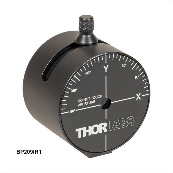 Zoom
Zoom| Key Specifications | ||||||
|---|---|---|---|---|---|---|
| Item #a | ||||||
| Wavelength Range | 200 - 1100 nm | 500 - 1700 nm | 900 - 2700 nm | |||
| Detector Material | UV-Enhanced Si | InGaAs | Extended InGaAs | |||
| Aperture Diameter | 9 mm | |||||
| Scan Methods | Scanning Slits, Knife Edge | |||||
| Slit Sizes | 5 µm and 25 µm | |||||
| 2.5 µm - 9 mm | ||||||

 Zoom
Zoom| Item # | M2MS-AL | M2MS | |
|---|---|---|---|
| Wavelength Range | 250 - 600 nma | 400 - 2700 nma | |
| Beam Profiler Compatibilityb | BC207UV(/M)c BP209-VIS(/M) BC210CU(/M)c |
BC207VIS(/M)d BP209-VIS(/M) BP209IR1(/M) BP209-IR2(/M) BC210CV(/M)d |
|
| Internal Translation Stage | Travel Range | 100 mm | |
| Velocity (Max) | 500 mm/s | ||
| Effective Translation Range | 200 mm (Total) ±100 mm (from Focal Point) |
||
| Lens Focal Length | 250 mm | ||
| Optical Axis Height | 70 mm (Without Additional Feet) |
||
| M² Measurement Range | ≥1.0 (No Upper Limit) | ||
| Typical M² Accuracy | ±5% (Depends on Optics and Alignment) |
||
| Minimum Detectable Divergence Angle | <0.1 mrad | ||
| Applicable Light Sources | CW, Pulseda | ||
| Typical Measurement Time | 15 - 30 s |
||
| General Specifications | |||
| Size | 300 mm x 175 mm x 109 mm (Without Beam Profiler) |
||
| Weight | 4.2 kg (Without Beam Profiler) |
||
- Combine with BP209 Scanning Slit Beam Profilers to Build
Complete M2 Measurement System - Mirrors for the 250 - 600 nm or 400 - 2700 nm Range
- Mounting Adapters for BC207 and BC210C* Series Camera Beam Profilers and BP209 Series Scanning Slit Beam Profilers
- Includes an Alignment Laser
These extension sets are designed to convert Thorlabs' Camera or Scanning Slit Beam Profilers into a fully automated, motorized M² measurement system. The
The beam profiler and focusing lens remain in a fixed position. For M2 measurements, the beam path length is varied using a movable retroreflector mounted on a translation stage, which has a translation range of 200 mm and a maximum velocity of 500 mm/s.
 Each extension kit ships with a Class 1 alignment laser.
The side of the M² measurement system features an integrated USB 2.0 hub, which has ports for the slit beam profiler, one other device such as the TSP01 USB temperature and humidity controller, and a mini USB output connection to a PC. The translation stage inside of the system also communicates with the computer through this hub. As the BC207 and BC210C series beam profilers use USB 3.0 ports, they should be connected directly to a PC using their included USB 3.0 cables when used with the M2MS(-AL) system. The M2 measurement system extension set is controlled via the Thorlabs Beam software package, which is also use to control our beam profilers (see the Software tab) and enables accurate measurements of a variety of beam-related parameters.
The housing of the M2 measurement rests on four feet at the corners created by a 0.5 mm deep relief cut in the base. A set of RDF1 rubber damping feet are included. Five M6 taps allow for the installion of four damping feet with one near each corner or in a configuration using three damping feet.
More information about these complete M² measurement systems can be found here.
*Users who purchased an M2 measurement system extension set before August 8, 2023 and wish to use a BC210C Series Camera Beam Profiler may receive the appropriate adapter by contacting Tech Sales.
Lenses Included with M2MS-AL*
Lenses with f = 250 mm Mounted in CXY1QF Quick Release Plate:
*Additional lenses for shorter UV wavelengths and the CXY1QF quick release front plate are available separately to enable further customization of the M2 measurement system.
Lenses Included with M2MS*
Lenses with f = 250 mm Mounted in CXY1QF Quick Release Plate:
- LA1461-A (AR Coated for 350 - 700 nm)
- LA1461-B (AR Coated for 650 - 1050 nm)
- LA1461-C (AR Coated for 1050 - 1700 nm)
- LA5255-D (AR Coated for 1650 - 3000 nm)
*Additional lenses for longer IR wavelengths and the CXY1QF quick release front plate are available separately to enable further customization of the M2 measurement system.
Accessories Included with M2MS-AL and M2MS
- Alignment Laser
- USB 2.0 to Mini B Cable, 3 m
- USB 2.0 to Mini B (Angled), 0.5 m
- 15 V, 3.0 A Power Supply
- 0.05" Hex Key
- 3 mm Balldriver
- 4 Rail Clamps
- 6 M4 Cap Screws

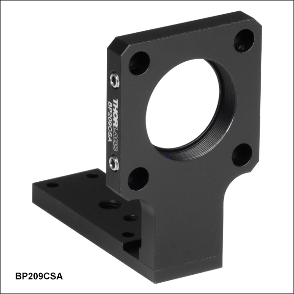 Zoom
Zoom- Adapts the BP209 Series Scanning Slit Beam Profilers to a 30 mm Cage System
- SM1 (1.035"-40) Threaded Bore
The BP209CSA(/M) Adapter can connect a Thorlabs' BP209 Series Scanning Slit Beam Profiler to a 30 mm cage system. An SM1 (1.035"-40) threaded bore in the adapter allows for compatibility with our Ø1" lens tubes or a Ø1" optic up to 3.6 mm (0.14") thick, when secured with a SM1RR retaining ring (not included). Four blind holes with 5/64" (2.0 mm) hex locking setscrews accept Ø6.0 mm cage rods (not included).
To mount the BP209CSA(/M) to a scanning slit beam profiler, first rotate the Y scan axis of the beam profiler to +60° or -60°, then turn the unit upside down, allowing access to the bottom mounting plate. Use the 2.0 mm (5/64") hex key included with the BP209CSA(/M) adapter to remove the four 5 mm long, M3 x 0.5 hex socket head screws*. Fully remove the bottom plate on the beam profiler, and mount the BP209CSA(/M) adapter in its place using the screws removed from the beam profiler.
*For BP209 Series Dual Scanning Slit Beam Profilers made prior to July 2022, the bottom plate is secured via four 5 mm long, M3 x 0.5 Phillips head screws. A #1 Phillips screwdriver (not included) is required to remove these screws.