 Products Home
Compact 5-Axis Pitch, Yaw, and Translation Stage
- X, Y, and Z Linear Translation Plus Pitch and Yaw Adjustment
- Compact Footprint: 2.36" x 2.15" (59.9 mm x 54.7 mm)
- Kit for Use with 3-Axis Flexure Stages
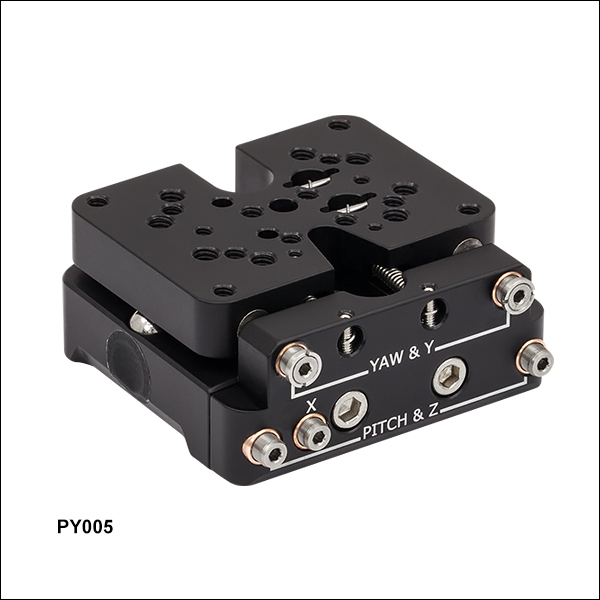
PY005
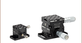
Back
Front
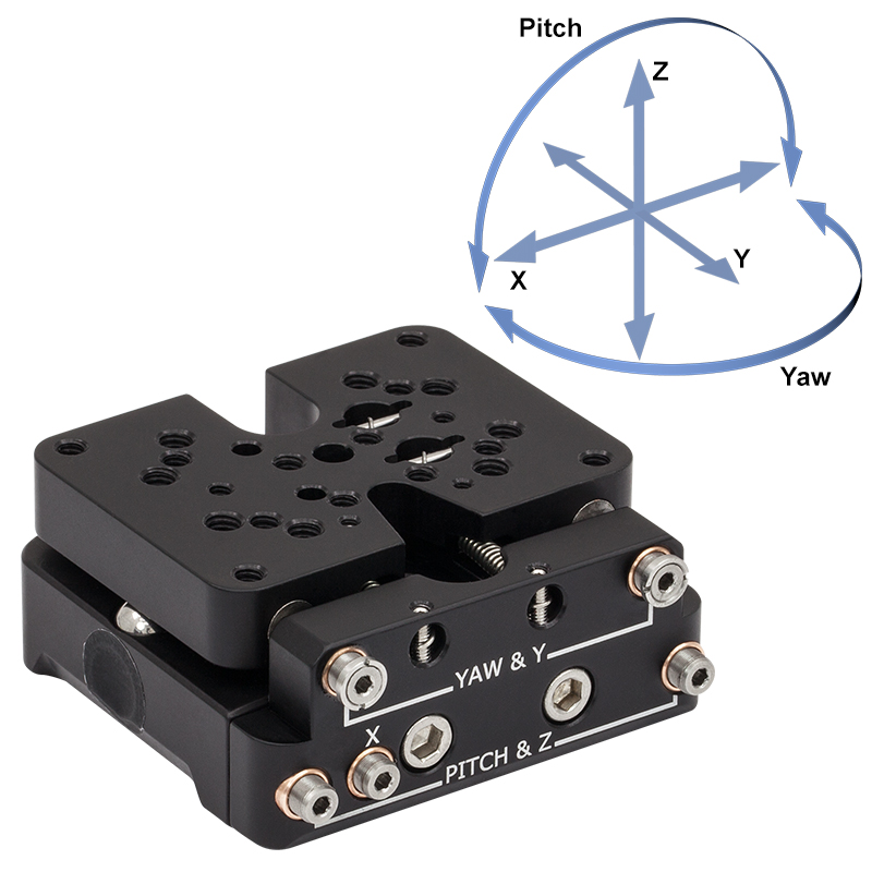
5 Degrees of Freedom
PY005 Translation
Platform Shown with
a PY005A1 Base Plate,
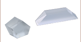
PM4 Clamping Arm, and Prism


Please Wait
| PY005(/M) Specifications | ||
|---|---|---|
| Travel Ranges | ||
| X, Y, and Z | 0.12" (3.0 mm) | |
| Yaw | ±5° | |
| Pitch | ±3.5° | |
| Resolution | ||
| X | 146.5 µm/rev | |
| Y | 254.0 µm/rev | |
| Z | 146.5 µm/rev | |
| Pitch | 2.90 mrad/rev | |
| Yaw | 6.25 mrad/rev | |
| Maximum Load | ||
| Platform Mounted Horizontally |
0.5 lb (0.23 kg) | |
| General Specifications | ||
| Dimensions | 2.36" x 2.15" x 1.08"a (59.9 mm x 54.7 mm x 27.3 mma) |
|
| Actuators | 5 x 100 TPI | |
Features
- Pitch, Yaw, X, Y, and Z Adjustment
- Compact 2.36" x 2.15" (59.9 mm x 54.7 mm) Footprint
- Assortment of Top Platform Mounting Holes
- Two 4-40 (M4) Tapped Holes
- Twelve 6-32 (Four M3 & Eight M4) Tapped Holes
- Eight 8-32 (M4) Tapped Holes
- One #8 (M4) Counterbore
- Kit and Accessories Sold Below for Compatibility with our 3-Axis Flexure Stages and Free-Space EO Modulators
The PY005 stage provides five axes of adjustment in an compact package measuring 2.36" x 2.15" x 1.08" (59.9 mm x 54.7 mm x 27.3 mm). It has five 100 TPI actuators for adjusting the top platform's pitch, yaw, X, Y, and Z positions. Two actuators together control the yaw and Y-axis position, two actuators together control the pitch and Z-axis position, and a single actuator controls the X-axis position. The actuators have a 5/64" (2 mm) hex for adjustments with a hex key or our HKTS-5/64 hex key thumbscrews. The base of the PY005 has two counterbored 1/4" (M6) slots, as shown in the photographs below, for mounting the stage to an optical table or to the mounting accessories sold below.
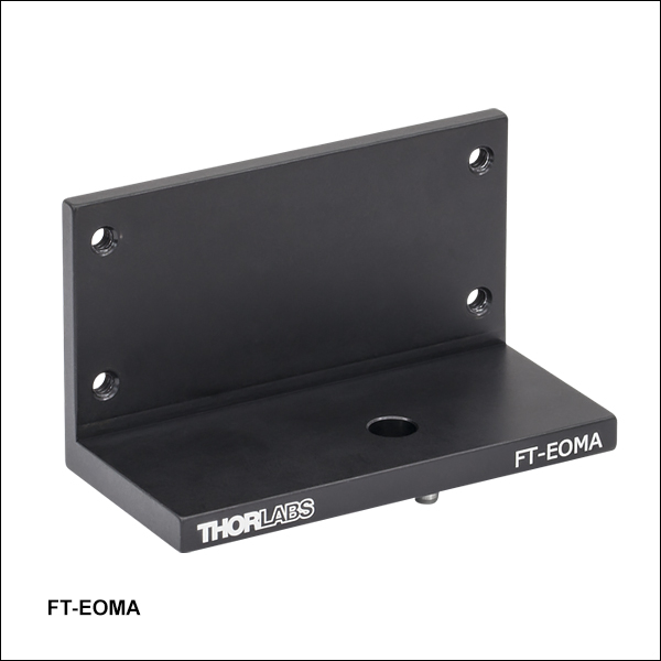
The translating top platform of the PY005 has a variety of mounting holes and taps that can be seen by clicking on the ![]() info icons in the tables below. These holes allow the platform to be used for many different applications. For instance, the eight 8-32 (M4) tapped holes and the #8 (M4) counterbore on the underside of the top platform, accessible from the bottom of the stage, allow optic mounts and other optomechanical components to be mounted on the platform, as well as the PM5(/M) stainless steel clamping arm. The eight 6-32 (M4) tapped holes are compatible with our PM3 and PM4 clamping arms (sold below). The holes are positioned so that the setscrew of the clamping arm is centered over the top platform. The two 4-40 (M4) tapped holes allow Ø1" optics to be mounted in our 30 mm cage optic mounts (Item # B5C1, B5CT1, or B5CT2). Additional 6-32 (M3) holes make the platform compatible with our FT-EOMA bracket (sold below) for compatibility with our EO modulators.
info icons in the tables below. These holes allow the platform to be used for many different applications. For instance, the eight 8-32 (M4) tapped holes and the #8 (M4) counterbore on the underside of the top platform, accessible from the bottom of the stage, allow optic mounts and other optomechanical components to be mounted on the platform, as well as the PM5(/M) stainless steel clamping arm. The eight 6-32 (M4) tapped holes are compatible with our PM3 and PM4 clamping arms (sold below). The holes are positioned so that the setscrew of the clamping arm is centered over the top platform. The two 4-40 (M4) tapped holes allow Ø1" optics to be mounted in our 30 mm cage optic mounts (Item # B5C1, B5CT1, or B5CT2). Additional 6-32 (M3) holes make the platform compatible with our FT-EOMA bracket (sold below) for compatibility with our EO modulators.
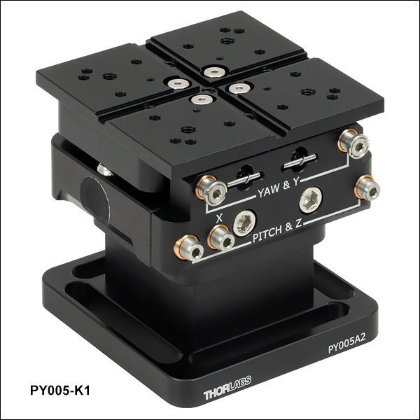
For use with our 3-Axis Flexure Stages, we offer the PY005-K1(/M) adapter kit that includes a pedestal base and flexure top plate. This kit has an overall deck height of 2.46" (62.5 mm) to match the deck height of the stages.
We also offer mounting bases to mount the PY005(/M) onto optical tables or breadboards.
| Posted Comments: | |
Geoff Heberle
(posted 2023-12-07 13:06:05.667) Are there any locking features for any of the adjusters? ksosnowski
(posted 2023-12-11 10:21:42.0) Hello Geoff, thanks for reaching out to Thorlabs. PY005 does not have any locking mechanism for the adjusters. The rings seen on the pitch/yaw axis adjusters are fixed hard-stops to prevent overtravel. user
(posted 2022-11-14 15:36:40.553) Dear Thorlabs Team,
you state a nominal height of 27.3mm. Does the travel range along z start from there going only upwards or does it also extend downwards? How is it split in the two directions? cdolbashian
(posted 2022-11-16 12:10:19.0) Thank you for reaching out to us with this inquiry. You raise a good point. To test this I measured the platform height in both the minimum and maximum positions. The minimum was ~25.1mm, while the max was ~28.3mm. Based on this, it seems like the 27.3 is the nominal middle point, but shouldn't be taken as an absolute mid-point Matthew Feldman
(posted 2022-08-19 09:23:26.997) I need to know the mechanical stability of this stage. You should provide data like you do with your Polaris mounts. jdelia
(posted 2022-08-23 03:16:06.0) Thank you for contacting Thorlabs. We unfortunately do not have this data on-hand at the moment. However, I can certainly pass your suggestion along to our internal team of engineers. Cristina Amaya
(posted 2022-06-10 17:07:21.407) Dear Thorlabs team,
I would like to know what is the precision to adjust the position of the PY005/M. I see you mentioned the resolution but that value is for a complete revolution of the knob. For a small increment (the minimum rotation a human hand can do), how much would this be. I've seen other manufacturers specify this precision for other products but I couldn't find it here in the specs of the stage.
Kind regards,
Cristina Amaya jdelia
(posted 2022-06-14 08:12:58.0) Thank you for contacting Thorlabs. We unfortunately do not specify this. We spec the minimum for 1 turn. It is very feasible, in a laboratory setting, to rotate the adjusters a single degree or less. In this case the minimum motion is limited to how small of a movement you can confidently achieve. Eric Lentz
(posted 2021-09-29 14:29:58.48) Hello,
I agree with an earlier comment that this product should have at least a basic manual.
What are the two, large center screws for and should they be tight? When I tighten them they move everything and then I run out of travel pretty quickly; when I loosen them the stage moves inconsistently and does not always return to its position.
And, is there a way to center the range of motion of the Y, Z, and their rotational components? The X is fine because you can center the top half (dynamic) on the botton half (static) pretty easily.
Thank you, Eric. cdolbashian
(posted 2021-10-11 03:16:29.0) Thank you for contacting us at Thorlabs and thank you for the feedback. Understandably, it can be a bit confusing selecting which of the hex screws to adjust for this part, since there are so many on the same face. The largest two should not be adjusted, as they function hold the device together. Loosening them will affect all of the tensions in different manners as this will allow space to form between the adjusters and the springs in which they tension. In future revisions of this product, we are looking at ways to make this clearer for the customers. I have reached out to you directly to discuss a possible solution for you! Ernesto Vasquez
(posted 2021-05-28 14:48:28.58) What is angular and linear sensitivity of PY005? YLohia
(posted 2021-06-04 10:12:25.0) Hello, the sensitivity of a purely manual mechanical device such as the PY005 is entirely dependent on the dexterity of the user. Phuc Nguyen
(posted 2020-11-11 21:12:37.707) What is the maximum weight load of PY005 in z-axis? What is the mass of PY005? Thanks. YLohia
(posted 2020-11-12 10:00:08.0) Hello, thank you for contacting Thorlabs. We do not recommend exceeding the torque on the center of the plate to be more than 3 in*lbs when used in a vertical orientation. Please also note that, when using in a vertical setting, the orientation should be set such that the X-Axis spring is being assisted by gravity, eliminating the X-Axis springs from the equation. The mass of the stage is 0.18 kg. Young Ho Yun
(posted 2020-07-06 01:39:56.337) Hello, the question is one.
= um / rev
Does rev mean 360 degrees in product specifications? YLohia
(posted 2020-07-06 01:39:33.0) Hello, thank you for contacting Thorlabs. Yes, one full revolution adjustment is equal to 360 degrees for this product. Jakub Chołodowski
(posted 2020-05-27 05:17:53.16) Dear Sir or Madame,
I have a few questions pertaining to the PY005 stage. Since the upper body of the stage (I mean the one where optical instruments are typically mounted) is connected to the base plate with some springs I would like to ask the following questions:
- Can the stage be oriented upside down during operation with no adverse influence on positioning accuracy? Is it possible that when the stage is oriented upside down, the upper body of the stage will lose contact with the balls underneath?
- Is the upper body susceptible to vibrations induced from the outside?
- Does the stage have some built in mechanism for "freezing" it after adjusting position and orientation of the upper body so that pottential oscillations of the upper body with respect to the base plate were avoided?
- Is there any chance to replace default springs embodied in the stage with some stiffer ones with no risk of excessive wear of the positioning screws?
Looking forward to hearing from you.
With best regards
Jakub Chołodowski llamb
(posted 2020-05-28 10:08:17.0) Hello Jakub, thank you for your feedback. For future technical application inquiries, please email your local Thorlabs Tech Support team (techsupport.se@thorlabs.com) directly. The PY005 stage is not designed for inverted usage, so we do not have specifications in this orientation as the springs would be working against gravity, either linearly or by a torque on the mounting platform. If you must use the stage in this configuration, it should only be with very light loads, such as our LRM1 lens mount and a singlet lens. The body is susceptible to external vibrations and does not feature a locking mechanism. Spring replacement may be possible but would require some further discussion of customization. I have reached out to you directly in this case to discuss your application further. Larry Siegel
(posted 2020-03-23 15:30:03.233) Can this be motorized? With piezo inertia actuators or others? Thx YLohia
(posted 2020-03-24 02:11:48.0) Hello, thank you for contacting Thorlabs. Unfortunately, these stages cannot be motorized since they utilize 3/16"-100 threads, which we currently do not have motorized (or piezo) actuators for. A motorization redesign for these was looked at in the past, but the screws are extremely close to each other which does not allow the X-axis motor to fit in. user
(posted 2018-12-07 16:24:20.98) Why does this separate product (PY005A1) even exist? The translation platform (PY005) itself should already come with something like this integrated. The fact that the underside of the translation platform is not flat presents a lot of problem mounting it on a 1 inch post for instance. Had to resort to homemade hack to get stable mounting on a post. Very bad design from Thorlabs. llamb
(posted 2018-12-10 10:36:22.0) Thank you for your feedback. The PY005 was designed to have a very compact footprint that can still be mounted to a table using the two counterbored holes, accessible from the top of the stage. The PY005A1 base adapter is sold separately for those that need more versatility when mounting to a table, but not necessarily the compact footprint. Table mounting was our main consideration when designing this product, as opposed to post-mounting. I have added this idea for a more centered Ø1" post adapter into our internal product forum for future discussion. I also see you did not leave a contact email, so feel free to reach out to techsupport@thorlabs.com with any further comments or questions. Thank you! cojoc
(posted 2018-08-10 12:28:36.253) We aquired 5 PY005/M stages assuming the 5-axis control is independent but it is not, i.e. to have Y translation both Y and yaw actuators should be adjusted, the same for pitch and Z. If this can be managed somehow (moving the actuators the same amount), the situation is much worse for yaw and pitch without translation. It would be useful to know where the rotation axes are for pitch and yaw. There is no manual avaialbe for this product. Please make it available, otherwhise what seems to be a nice product is just of little usefulness. llamb
(posted 2018-08-24 03:02:10.0) Thank you for contacting Thorlabs. Only the X-axis adjustment is decoupled in the PY005. The rotation axes for pitch and yaw depend on the other actuators as well since these are coupled together. These rotation axes are best seen in comparison to the ball locations as well as the springs inside this mount. These can be seen in the 3D model files more easily. I will reach out to you directly for further explanation. thorsten.fuehrer
(posted 2016-05-11 11:11:19.347) What's the maximum load if mounted vertically, i.e. with the adjustment screws pointing upwards? besembeson
(posted 2016-05-12 03:08:37.0) Response from Bweh at Thorlabs USA: We don't have specifications for this configuration. We don't also recommend using the stage in this orientation as the springs are working against gravity either linearly or by a torque on the mounting platform. If you have to use in this way, it should only be with light loads such as a LMR1 with an optic at most. couturier
(posted 2014-10-14 03:29:07.01) Is there a way to get PY005A2 with a custom height?
I would like to use the PY005 for aligning an AOM whose aperture should be at 3". I couldn't find a way to achieve this height.
Is there some way to do that? jlow
(posted 2014-10-22 02:40:50.0) Response from Jeremy at Thorlabs: We can possibly do this as a custom. However, there might be other options available. I will contact you directly to discuss about your requirement. |
 Deck Height")
 Zoom
Zoom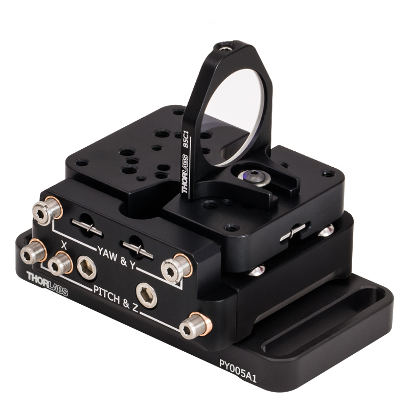
| Top Plate Mounting Holes | |
|---|---|
| PY005 |  |
| PY005/M |  |
- 27.4 mm (1.08") Deck Height
- Compact Stage with Five Degrees of Freedom
- 100 TPI Adjusters
- ±3.5° Pitch Adjustment, ±5° Yaw Adjustment, 3 mm Linear Translation (X, Y, and Z)
The PY005 is a compact stage with five degrees of freedom. Two actuators adjust the yaw and Y-axis, two actuators adjust the pitch and Z-axis, and a single actuator adjusts the X-axis. A variety of mounting holes are provided on the stage's top mounting platform for compatibility with many of our optomechanical components, including the mounting adapters sold below. A diagram of the mounting holes can be accessed by clicking on the info icon in the table above.
 Deck Height")
 Zoom
Zoom| Top Plate Mounting Holes | |
|---|---|
| PY005-K1 |  |
| PY005-K1/M |  |
Click to Enlarge
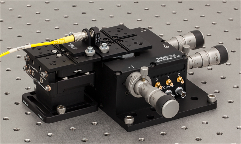
The PY005-K1 Used with a 3-Axis Flexure Stage for Fiber Coupling
- 62.5 mm (2.46") Deck Height Compatible with 3-Axis Flexure Stages
- Alignment Groove for Accessories (See Table Below)
- 8-32 (M4), 6-32 (M3), and 4-40 (M2) Taps
The PY005-K1(/M) includes a PY005(/M) stage, a PY005A2(/M) pedestal base (available separately below) and a top plate that give the PY005 a 62.5 mm (2.46") deck height. The top plate features 8-32,


 Zoom
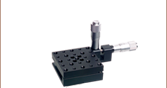
Zoom- Mounts the PY005(/M) onto an Optical Table or Breadboard
- PY005A1(/M) Gives PY005(/M) 1.44" Deck Height
- PY005A2(/M) Gives PY005(/M) 2.31" Deck Height
The PY005A1(/M) and PY005A2(/M) mounting bases allow the PY005(/M) stage to be mounted onto optical tables or breadboards. Both bases include 1/4"-20 (M6) cap screws for mounting the stage onto the base.
The PY005A1(/M) has two slots for 1/4"-20 (M6) cap screws for mounting onto breadboards. Additionally, instead of using the slots, the base can be clamped onto the table using CL5 table clamps. The PY005(/M) can be mounted with the adjusters facing either the long or short sides of the base. When the PY005(/M) is mounted onto the PY005A1(/M), it has a deck height of 1.44" (36.6 mm).
The PY005A2(/M) has four slots for 1/4"-20 (M6) cap screws. When the PY005(/M) is mounted onto the PY005A2(/M), it has a deck height of 2.31" (58.7 mm).

 Zoom
Zoom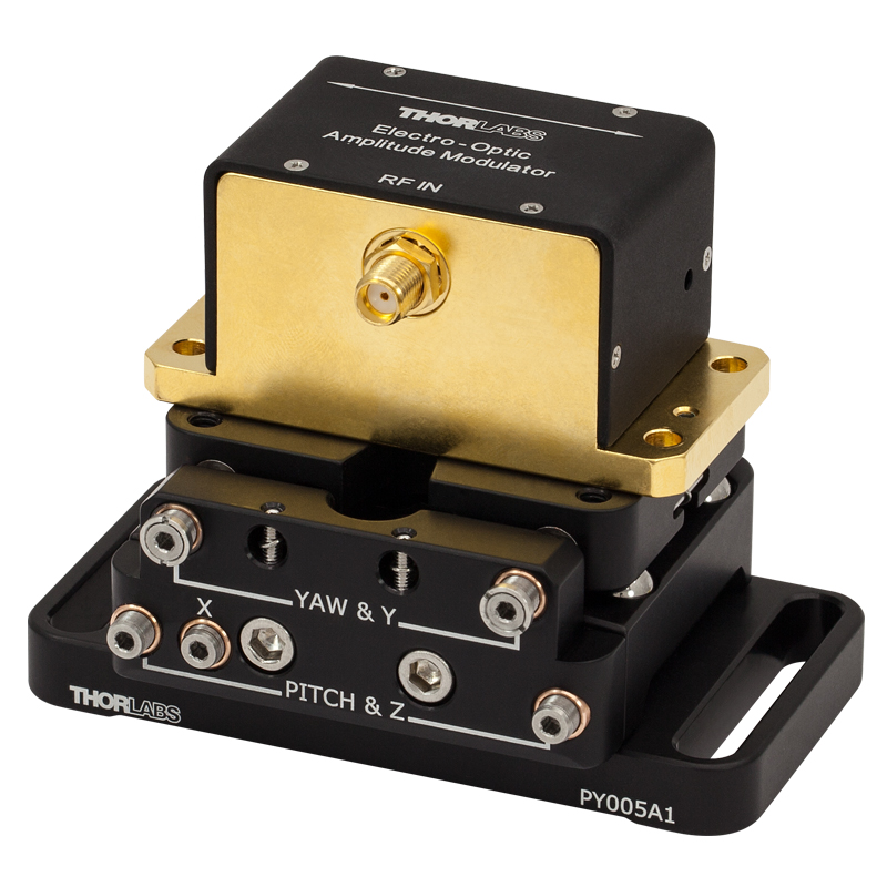
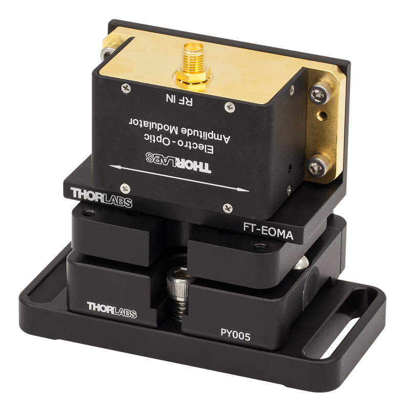
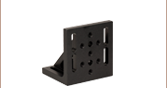
Our EO Modulators Can Be Mounted Using the FT-EOMA Bracket and PY005A1 Base (Left) for a 2" (50.8 mm) Beam Height or Directly to the PY005 (Right)
- Mounts our Free-Space EO Modulators onto the PY005(/M)
- PY005A1(/M) and FT-EOMA Used Together Mount EO Modulators with a 2" (50.8 mm) Nominal Beam Height
- Includes 6-32 (M3) Screws for Mounting
The FT-EOMA adapter allows our free-space electro-optic (EO) modulators to be mounted to the stage. When the PY005A1(/M) and FT-EOMA are used together, the optical axis of the EO modulator is positioned at a height of 2" (50.8 mm) from the optical table. The adapter allows the modulator to easily be taken off the stage without unmounting the stage from the optical table. An EO modulator can also be mounted directly to the PY005(/M) using the #8 (M4) counterbore accessible from the bottom of the stage. This counterbore is accessible even when the PY005A1(/M) is mounted to the bottom of the stage.

 Zoom
Zoom
Click for Details
Mechanical Drawings
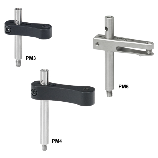
- Provide Clamping Force for Our Platform Mounts
- Threaded Hole on Top and Threaded Stud on Bottom of Post
- 6-32 Threads on PM3 and PM4
- 8-32 Threads on PM5
- M4 x 0.7 Threads on All Metric Versions
- Maximum Optic Heights from 0.97" to 1.65" (24.6 mm to 41.8 mm)
- Extension Posts Available to Increase Max Optic Height
- PM3SP(/M) with PM3(/M): Hold Optics up to 2.21" (56.1 mm) Tall
- PM4SP(/M) with PM4(/M): Hold Optics up to 3.61" (91.7 mm) Tall
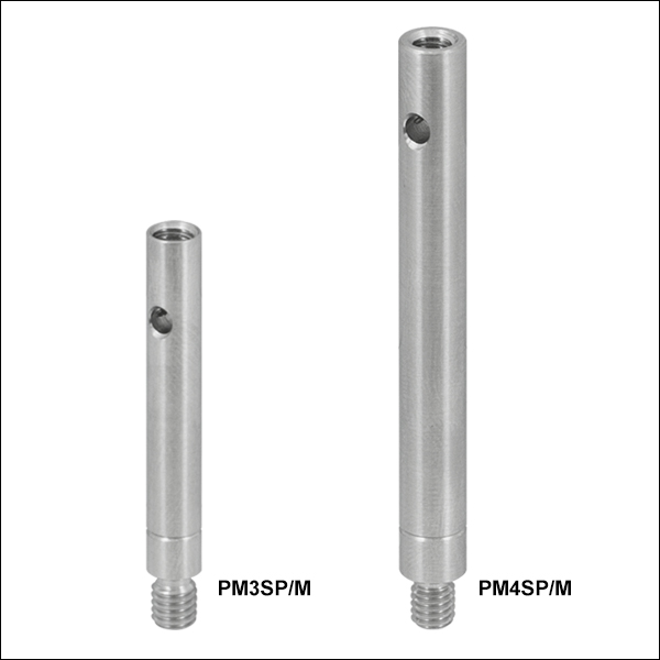
Click to Enlarge
Clamping Arm Extension Posts with Metric Indicator Groove
Thorlabs' Clamping Arms provide clamping force to secure optics to our kinematic platform mounts, stages, and V-clamps. The PM3(/M) accommodates optics up to 0.97" tall and features a 0.69" center-to-center distance between the post and the nylon-tipped setscrew that holds the optic. The PM4(/M) accommodates optics up to 1.61" and features a 1.16" center-to-center distance between the post and the nylon-tipped setscrew. The maximum optic height of the PM3(/M) or PM4(/M) Clamping Arms can be extended using our PM3SP(/M) or PM4SP(/M) Extension Posts, respectively. These extension posts are identical to the posts included in each complete clamping arm. Each clamping arm features 6-32 (M4 x 0.7) threads. The PM3 and PM4 can be mounted in 8-32 tapped holes by using the AS6E8E thread adapter, which features internal 6-32 threads and external 8-32 threads. This thread adapter has an outer diameter of 0.24", which is the same as the PM4SP extension post and the post included with the PM4 clamping arm. This allows the clamping arm to be adjusted across the seam between either post and the adapter. The smaller diameters of the included post for the PM3 clamping arm and the PM3SP extension post cause the thread adapter to act as a stop for the clamping arm.
The PM5(/M) clamping arm is made entirely from heat-treated stainless steel, which helps maintain stability in fluctuating temperatures and provides vacuum compatibility. This clamping arm is recommended for use with the POLARIS-K1M4(/M), but it can be used with any platform mount or stage that has one or more 8-32 (M4 x 0.7) tapped holes. The PM5(/M) can hold optics up to 1.65" tall, and the distance from the post center to the contact point that holds the optic is 0.90".
Each clamping arm is attached to its post using a flexure mechanism that locks with a 5/64" (2.0 mm) balldriver or hex key. The setscrew on top of the clamping arm also accepts a 5/64" (2.0 mm) balldriver or hex key in order to clamp down on the optic. The post includes a through hole which can be leveraged for added torque when tightening down the post. Please see the diagram above for additional information.