 Products Home / Optical Fiber & Fiber Patch Cables / Multimode Fiber Bundles / Fiber Optic Reflection/Backscatter Probe Bundles
Fiber Optic Reflection/Backscatter Probe Bundles
- Fiber Y-Bundles for Reflection and Backscatter Spectroscopy
- Legs for Light Source, Sample, and Spectrometer
- Sample Leg Options: SMA Connector or Ø1/4" Probe
- Ø200 µm Core Low-OH, High-OH, or ZBLAN Multimode Fiber
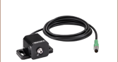
Sample End
RP24
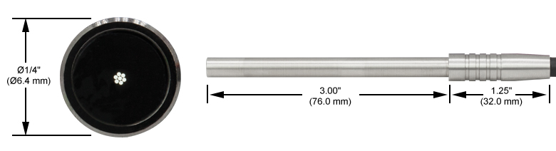
Reflection Probe with Ø1/4" Probe
Sample Leg to SMA Connectors,
Linear Configuration Spectrometer Leg
Light Source End
Linear
Spectrometer End
Spectrometer
End
Round Light
Source End
Sample End
RP20
Reflection Probe with SMA Connectors
and Round Configuration Light Source Leg


Please Wait
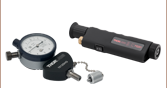
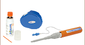
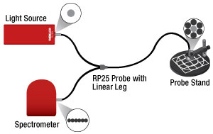
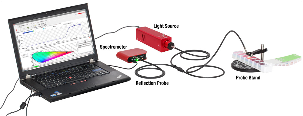
Typical Reflection Spectroscopy Setup

Click to Enlarge
Typical reflection spectroscopy setup using Thorlabs' reflection probe with SMA connectors, reflection probe holder, CCD spectrometer, and broadband fiber-coupled light source. Note: The positioning of the fibers in the light source end is not guaranteed to match the schematic.
Click to Enlarge
Low- and high-OH silica fibers provide better attenution at visible wavelengths, while the ZBLAN fiber provides low, relatively flat attenuation for wavelengths from 2.0 - 3.6 µm.
Features
- Fiber Optic Y-Cables for Reflection and Fluorescence Spectroscopy
- Three Wavelength Ranges Available
- 250 - 1200 nm
- 400 - 2400 nm
- 285 - 4500 nm
- Sample Leg Available with SMA905 Connector or Ø1/4" Probe
- Light Source End Illuminates Sample End for Sample Viewing
- Spectrometer End Carries Reflected Light from Sample
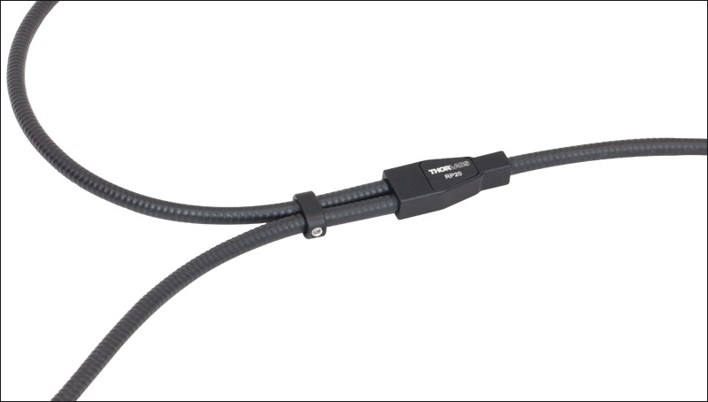
- Reinforced Stainless Steel Tubing and Steel Strain Relief Sleeves for Durability
- Y-Joint with Adjustable Fiber Clamp
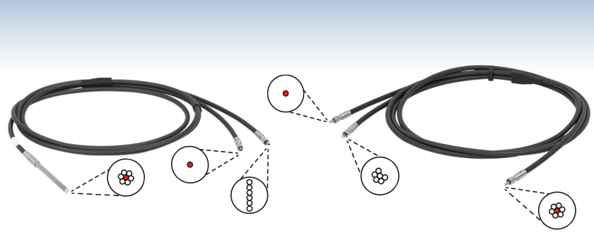
Thorlabs' Fiber Bundle Probes are optimized for measuring diffuse and specular reflectance, color, fluorescence, and backscattering of solid, liquid, and powder samples. They are bifurcated fiber cables with a leg to carry light from a source to a sample and a leg to carry light reflected by the sample to a spectrometer. Each bundle uses Ø200 µm core multimode fiber. Silica fiber bundles with either a high or low hydroxyl ion (OH) content are for use in the 250 - 1200 nm or 400 - 2400 nm range, respectively. Bundles using ZBLAN† fiber can be used in the 285 - 4500 nm range, but are specifically designed for use in the mid-IR. See the plot to the lower right for a comparison of the attenuation for each fiber type used in these bundles.
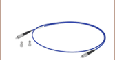
These fiber bundles each have a sample leg with either an SMA905 connector for ease of integration into existing fiber systems or a Ø1/4" (Ø6.35 mm) probe for manual applications. Both types of fiber bundles have light source and spectrometer legs with SMA905 connectors for compatibility with most spectrometers and light sources (see the Application tab for details).
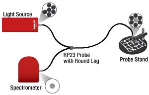
Reflection probes with Ø1/4" probe sample legs are available with two different configurations. Probes with a round bundle light source leg and a single-fiber spectrometer leg are ideal for maximizing light delivered to the sample and are suitable for general applications. Bundles with a single-fiber light source leg and a linear bundle spectrometer leg are intended for samples that are sensitive to light exposure or heating caused by absorption (see the Round vs Linear Leg tab for more information).
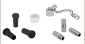
The low- and high-OH fiber patch cables include three rubber protective caps that shield the connector ends from dust and other hazards. For increased durability, these cables incorporate plastic-covered stainless steel protective tubing (FT061PS) and have reinforced metal strain relief boots. The ZBLAN patch cables include threaded metal protective caps for the SMA connector ends, and the RP31 ZBLAN cable also includes one rubber protective cap for the Ø1/4" probe sample end. If additional caps are needed for the SMA-terminated ends, the CAPSM Metal-Threaded Fiber Caps are available separately. These ZBLAN patch cables also incorporate stainless steel protective tubing and have reinforced metal strain relief boots.
Thorlabs also offers reflection/backscatter probes with an added reference leg. These probe bundles are ideal for use in applications where fluctuations in the source have a negative impact on spectral data.
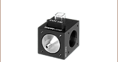
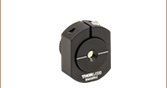
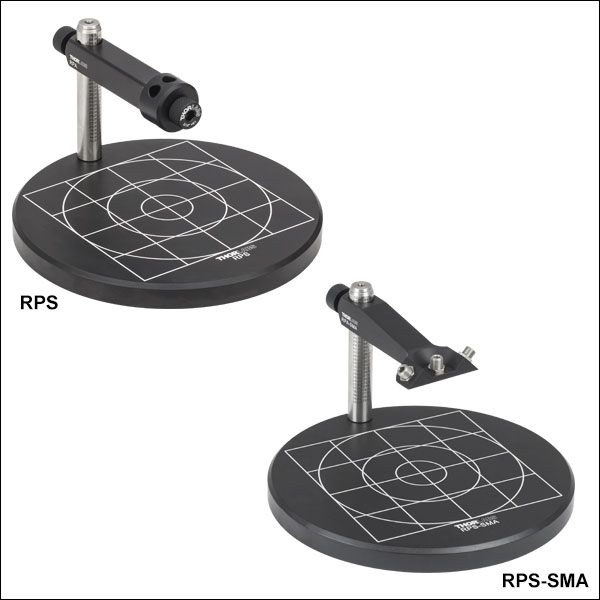
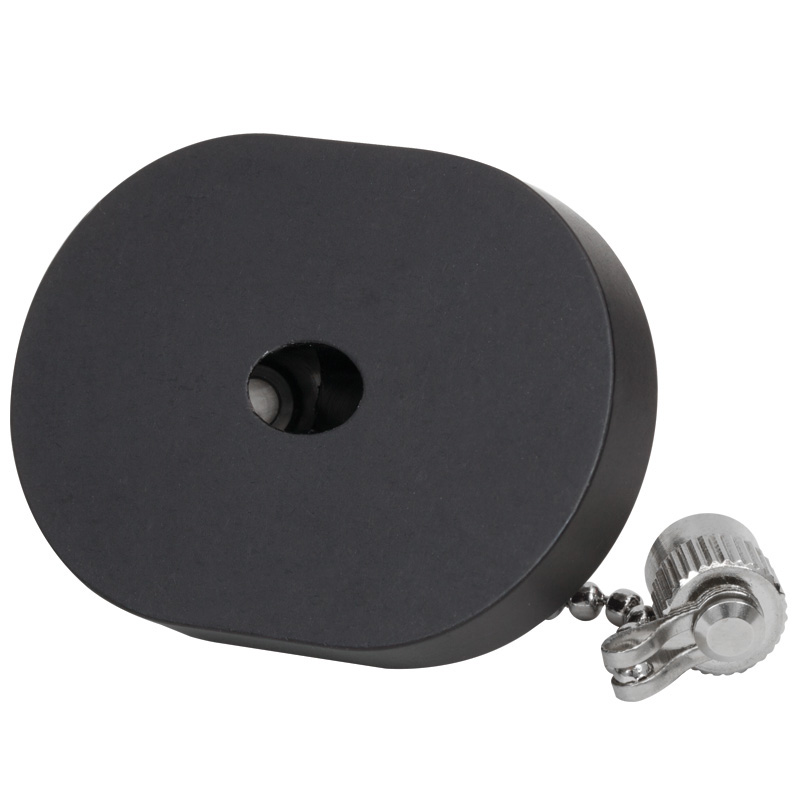
Reflection Probe Holders
Thorlabs offers fiber probe stands and holders (sold below). The SMA terminated sample end can be mounted using the RPS-SMA stand or RPH-SMA holder, while the Ø1/4" probe sample end is mounted using the RPS stand or RPH holder. Both options secure the sample end probe or SMA connector in close proximity to a sample. They are easily adjustable and will not allow the fiber to move during measurements. Fiber optic probes can be secured with a vertical orientation for specular reflection spectroscopy, or at 45° for diffuse reflection spectroscopy.
† ZBLAN and ZrF4 are used interchangeably to refer to fluorozirconate glass.
Click to Enlarge
Each bifurcated cable has a durable aluminum Y-joint and includes an adjustable fiber clamp (RP20 shown above).

Click to Enlarge
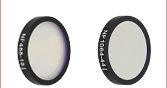
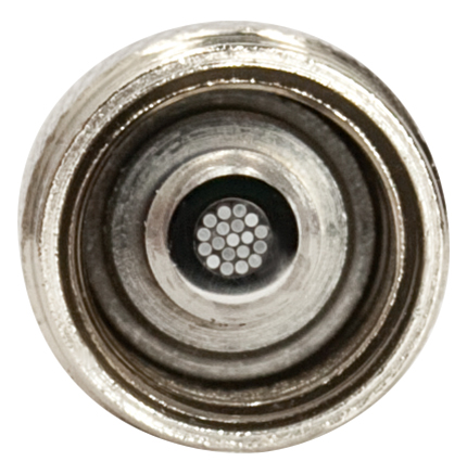
Core size, wavelength range, and NA information are engraved on the sample end strain relief sleeve of the SMA probes. Fiber configuration is engraved on the opposite side of the sleeve, as shown below.
Click to Enlarge
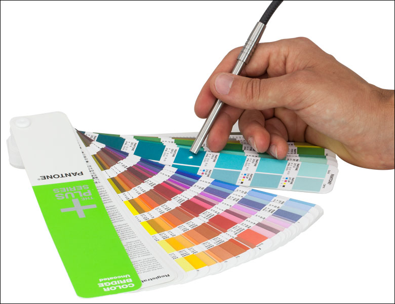
RP22 Reflection Probe with Ø1/4" Probe Being Used to Make a Diffuse Reflection Color Measurement
| Bundles Selection Guide | |||||||||
|---|---|---|---|---|---|---|---|---|---|
| Straight | Bifurcated | Fan-Out | |||||||
 |
 |
 |
 |
 |
 |
 |
 |
 |
|
| Round | Linear to Linear |
Round to Linear |
Standard 2-Fiber Y-Bundle Optogenetics 2-Fiber Y-Bundle |
19-Fiber Y-Bundle |
Reflection Probes |
Reflection Probes with Reference Leg |
Transmission Dip Probes |
1-to-4 | Standard 1-to-7 Optogenetics 1-to-7 |
| All Fiber Patch Cables | |||||||||
| Bundles with SMA Connector Sample Legs | |||||
|---|---|---|---|---|---|
| Item # | RP20 | RP21 | RP28 | RP29 | RP30 |
| Light Source Leg | SMA Connector 6 Illumination Fibers, Round Configurationa |
SMA Connector 1 Illumination Fiber |
SMA Connector 6 Illumination Fibers, Round Configurationa |
||
| Fiber Configuration, Terminator Side View (Click for Details) |
 |
 |
 |
||
| Sample Leg | SMA Connector 7 Fibers, Round Configuration, Read Fiber in Center |
SMA Connector 7 Fibers, Round Configuration, Illumination Fiber in Center |
SMA Connector 7 Fibers, Round Configuration, Read Fiber in Center |
||
| Fiber Configuration, Terminator Side View (Click for Details) |
 |
 |
|||
| Spectrometer Leg | SMA Connector 1 Read Fiber |
SMA Connector 6 Read Fibers, Linear Configuration |
SMA Connector 1 Read Fiber |
||
| Fiber Configuration, Terminator Side View (Click for Details) |
|
 |
 |
||
| Specifications | |||||
| Wavelength Range | 250 - 1200 nmb | 400 - 2400 nm | 250 - 1200 nmb | 400 - 2400 nm | 285 - 4500 nmc |
| Fiber Type | FG200UEA | FG200LEA | FG200UEA | FG200LEA | ZBLAN Multimode |
| Hydroxyl Ion Content | High OH | Low OH | High OH | Low OH | - |
| Fiber Core Size | Ø200 ± 4 µm | Ø200 µm ± 10 µm | |||
| Fiber Cladding Diameter | 220 ± 2 µm | 290 ± 10 µm | |||
| Fiber NAd | 0.22 ± 0.02 | 0.20 ± 0.02 @ 2.0 µm | |||
| Fiber Attenuation Plot |  |
 |
|||
| Minimum Bend Radius | Short Term: 23 mme Long Term: 46 mme |
140 mm ± 30 mmf | |||
| Length | 2 +0.075/-0.0 m | 1 +0.2/-0.0 m | |||
| Bundles with Ø1/4" Probe Sample Legs | ||||||
|---|---|---|---|---|---|---|
| Item # | RP22 | RP23 | RP24 | RP25 | RP31 | |
| Light Source Leg | SMA Connector 6 Illumination Fibers, Round Configurationa |
SMA Connector 1 Illumination Fiber |
SMA Connector 6 Illumination Fibers, Round Configurationa |
|||
| Fiber Configuration, Terminator Side View (Click for Details) |
|
|
|
|||
| Sample Leg | Ø1/4" Probeb 7 Fibers, Round Configuration, Read Fiber in Center |
Ø1/4" Probeb 7 Fibers, Round Configuration, Illumination Fiber in Center |
Ø1/4" Probeb 7 Fibers, Round Configuration, Read Fiber in Center |
|||
| Fiber Configuration, Terminator Side View (Click for Details) |
 |
 |
||||
| Spectrometer Leg | SMA Connector 1 Read Fiber |
SMA Connector 6 Read Fibers, Linear Configuration |
SMA Connector 1 Read Fiber |
|||
| Fiber Configuration, Terminator Side View (Click for Details) |
|
|
|
|||
| Specifications | ||||||
| Wavelength Range | 250 - 1200 nmc | 400 - 2400 nm | 250 - 1200 nmc | 400 - 2400 nm | 285 - 4500 nmd | |
| Fiber Type | FG200UEA | FG200LEA | FG200UEA | FG200LEA | ZBLAN Multimode | |
| Hydroxyl Ion Content | High OH | Low OH | High OH | Low OH | - | |
| Fiber Core Size | Ø200 ± 4 µm | Ø200 ± 10 µm | ||||
| Fiber Cladding Diameter |
220 ± 2 µm | 290 ± 10 µm | ||||
| Fiber NAe | 0.22 ± 0.02 | 0.20 ± 0.02 @ 2.0 µm | ||||
| Fiber Attenuation Plot |
|
|
||||
| Minimum Bend Radius | Short Term: 23 mmf Long Term: 46 mmf |
140 mm ± 30 mmg | ||||
| Length | 2 +0.075/-0.0 m | 1 +0.2/-0.0 m | ||||
Round vs. Linear Leg Fiber Probes
Our reflection probes are offered with a 6 fiber bundle leg in either a round or linear configuration. The round bundle probes (RP20, RP21, RP22, RP23, RP30, and RP31), shown below and to the left, are intended to be coupled to the light source to maximize transmission to the sample.
Linear bundle probes (RP24, RP25, RP28, and RP29), shown below and to the right, are intended to be coupled to a spectrometer with a vertical slit, such as our compact spectrometers. The design limits the amount of light transmitted to the sample while maintaining the amount of transmitted light to the spectrometer. This protects samples that are sensitive to light exposure or heating caused by absorption. To maximize the amount of light coupled into the spectrometer, the engraving on the linear bundle’s sleeve should be aligned with the top of the spectrometer when the spectrometer is laid flat on the table.
Throughput Comparison
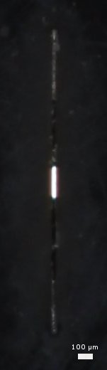
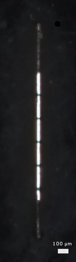
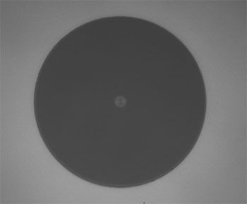
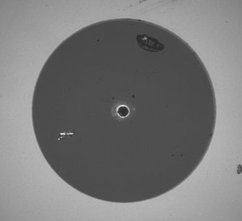
The entrance slit photos below illustrate how a single fiber and a linear fiber bundle couple with the entrance slit of the spectrometer. The linear bundle more closely matches the geometry of the slit than that from a single fiber patch cable. To achieve this, the linear bundle leg must be aligned with the engraving facing up when the spectrometer is laid flat on a table. The round bundle probes can be used in reverse with similar performance as the linear bundles so long as the bundle matches the geometry of the spectrometer’s entrance slit. This is not the case for our compact spectrometers, which have a linear entrance slit (shown below), so throughput will be severely compromised in this configuration.
When the linear leg is connected and properly aligned to the spectrometer, probes with a linear leg provide a similar net throughput compared to the round probes. This is because the fiber bundle either increases the light throughput from the source to the sample (round bundle) or from the sample to the spectrometer (linear bundle). The graph below compares the spectra produced by a MBB1F1 broadband fiber-coupled LED source reflected by a broadband mirror and measured using a CCS200 spectrometer. The datasets were obtained with an RP23 round leg bundle and an RP25 linear leg bundle configured in the same way at the two diagrams above.
Click to Enlarge
Click to Enlarge
Left: Light exiting the end face of an M25L01 fiber patch cable placed behind the 20 µm x 2 mm entrance slit of the CCS200 spectrometer.
Right: Light exiting the end face of a linear fiber bundle placed behind the 20 µm x 2 mm entrance slit of the CCS200 spectrometer. Note: The outer fiber of the bundle is truncated by an internal Ø1.2 mm aperture adjacent to the slit in the spectrometer (see the compact spectrometers Specs tab for details).
Click to Enlarge
Comparison of the spectra of an MBB1F1 broadband LED source reflected by a mirror and obtained with a CCS200 spectrometer. See the diagrams above for the fiber probe configurations.
Reflection Spectroscopy Application
These reflection spectroscopy probes can be used along with our CCD spectrometers, broadband fiber-coupled light sources, and the fiber probe holders sold below to take diffuse reflection, specular reflection, and color measurements.
Spectrometers
Thorlabs offers several CCD-based spectrometers for use in the visible, NIR, or UV to NIR spectral ranges. The CCS100 and CCS175 operate in the 350 - 700 nm and 500 - 1000 nm spectral ranges with 0.5 nm and 0.6 nm resolution, respectively. The extended-range CCS200 operates in the 200 - 1000 nm spectral range with 2.0 nm resolution, but the UV range may be heavily attenuated when analyzing broadband spectra.
Light Sources
The SLS201L tungsten-halogen broadband fiber-coupled light source delivers a 2796 K blackbody-type spectrum in the 360 - 2600 nm wavelength range and has active electronic stabilization for low spectral and intensity drift. Alternatively, the SLS203L provides free space output with a 1500 K temperature and 500 - 9000 nm emission range. We also offer fiber-coupled LEDs available with a selection of peak wavelengths or a broadband white-light emission spectra and our line of fiber-coupled laser sources offers a selection of options for intense single-wavelength illumination.
Click to Enlarge
Diffuse Measurement Taken at 45° Using RPH Holder Block
Reflection Probe Fiber Bundles
Thorlabs offers reflection probes with either high-OH or low-OH multimode fiber for wavelengths from 250 - 1200 nm and 400 - 2400 nm, respectively. Probes are available with a sample end that terminates in either a Ø1/4" probe or an SMA905 connector. We also offer Ø1/4" and SMA-terminated probes with linear fiber bundle spectrometer ends; these provide increased spectrometer coupling efficiency for samples with low reflectance.
If the coaxial illumination provided by a reflection probe bundle is not critical, separate fiber patch cables or bundles with SMA connectors can be used for illumination and signal collection. Our large-core round bundles maximize illumination intensity, while our single-fiber multimode SMA patch cables are useful for precise illumination, or for connection to a fiber-coupled laser. We also offer round-to-linear fiber bundles, which maximize signal strength at the spectrometer.
Reflection Probe Holders
Thorlabs offers the RPS and RPS-SMA fiber probe stands (RPS-SMA shown above and to the right), which allow for precise, stable positioning of the fiber optic probe at an angle of 90° or 45° relative to the sample. The probe holder arms (also sold separately) can also be integrated into other optomechanical setups using Ø1/2" posts. Alternatively, the RPH and RPH-SMA probe holder blocks sit directly on a sample, allowing the fiber tip to be positioned close to the surface and also blocking out room lights from the area under test.
Click to Enlarge
Custom 1-to-4 Fan-Out Cable
Custom Fiber Bundles
Thorlabs is pleased to offer custom straight and fan-out fiber bundles with random or mapped fiber configurations. The table below outlines some of our current bundle production capabilities. We are in the process of expanding these production capabilities, so do not hesitate to inquire if you do not see the bundle that you require described here.
Some custom bundles will require techniques outside of our usual production processes. As a result, we cannot guarantee that we will be able to make a bundle configuration to fit the requirements of your specific application. However, our engineers will be happy to work with you to determine if Thorlabs can produce a fiber bundle that fulfills your needs. To receive a quote, please provide a drawing or draft of your bundle configuration.

Click to Enlarge
Custom Silica Fiber Bundle with SMA905 Connectors
| Custom Bundle Capabilities | |||
|---|---|---|---|
| Bundle Configuration |
Straighta | Fan Out (2 or More Legs)a,b | |
| Fiber Types |
Single Mode | Standard (320 to 2100 nm), Ultra-High NA (960 to 1600 nm), Photosensitive (980 to 1600 nm) |
|
| Multimode | 0.10 NA Step Index (280 to 750 nm), 0.22 NA Step Index (190 to 2500 nm), 0.39 NA Step Index (300 to 2200 nm), Multimode Graded Index (750 to 1450 nm), Multimode ZrF4 (285 nm to 4.5 µm) |
||
| Tubing Optionsc | Thorlabs' Stock Furcation Tubing, Stainless Steel Tubing or Black Heat Shrink Tubing | ||
| Connectors | SMA905 (Ø2 mm Max Cored), FC/PC (Ø800 µm Max Cored), Ø1/4" Probe, or Flat-Cleaved Unterminated Fiber |
||
| Length Tolerancee | ±0.14 m | ||
| Active Area Geometryf |
Round or Linear | ||
| Angle Polishing | On Special Request. Available for up to Ø105 µm Core on Single Fiber End. Please Inquire for More Information. |
||
Our cable engineers are available to help manufacture a bundle for your application.
Please contact techsales@thorlabs.com with your custom bundle requests.
Please provide a drawing or draft of your custom bundle to expedite quote processing.
| Quick Links |
|---|
| Damage at the Air / Glass Interface |
| Intrinsic Damage Threshold |
| Preparation and Handling of Optical Fibers |
Laser-Induced Damage in Silica Optical Fibers
The following tutorial details damage mechanisms relevant to unterminated (bare) fiber, terminated optical fiber, and other fiber components from laser light sources. These mechanisms include damage that occurs at the air / glass interface (when free-space coupling or when using connectors) and in the optical fiber itself. A fiber component, such as a bare fiber, patch cable, or fused coupler, may have multiple potential avenues for damage (e.g., connectors, fiber end faces, and the device itself). The maximum power that a fiber can handle will always be limited by the lowest limit of any of these damage mechanisms.
While the damage threshold can be estimated using scaling relations and general rules, absolute damage thresholds in optical fibers are very application dependent and user specific. Users can use this guide to estimate a safe power level that minimizes the risk of damage. Following all appropriate preparation and handling guidelines, users should be able to operate a fiber component up to the specified maximum power level; if no maximum is specified for a component, users should abide by the "practical safe level" described below for safe operation of the component. Factors that can reduce power handling and cause damage to a fiber component include, but are not limited to, misalignment during fiber coupling, contamination of the fiber end face, or imperfections in the fiber itself. For further discussion about an optical fiber’s power handling abilities for a specific application, please contact Thorlabs’ Tech Support.
Click to Enlarge
Undamaged Fiber End
Click to Enlarge
Damaged Fiber End
Damage at the Air / Glass Interface
There are several potential damage mechanisms that can occur at the air / glass interface. Light is incident on this interface when free-space coupling or when two fibers are mated using optical connectors. High-intensity light can damage the end face leading to reduced power handling and permanent damage to the fiber. For fibers terminated with optical connectors where the connectors are fixed to the fiber ends using epoxy, the heat generated by high-intensity light can burn the epoxy and leave residues on the fiber facet directly in the beam path.
| Estimated Optical Power Densities on Air / Glass Interfacea | ||
|---|---|---|
| Type | Theoretical Damage Thresholdb | Practical Safe Levelc |
| CW (Average Power) |
~1 MW/cm2 | ~250 kW/cm2 |
| 10 ns Pulsed (Peak Power) |
~5 GW/cm2 | ~1 GW/cm2 |
Damage Mechanisms on the Bare Fiber End Face
Damage mechanisms on a fiber end face can be modeled similarly to bulk optics, and industry-standard damage thresholds for UV Fused Silica substrates can be applied to silica-based fiber. However, unlike bulk optics, the relevant surface areas and beam diameters involved at the air / glass interface of an optical fiber are very small, particularly for coupling into single mode (SM) fiber. therefore, for a given power density, the power incident on the fiber needs to be lower for a smaller beam diameter.
The table to the right lists two thresholds for optical power densities: a theoretical damage threshold and a "practical safe level". In general, the theoretical damage threshold represents the estimated maximum power density that can be incident on the fiber end face without risking damage with very good fiber end face and coupling conditions. The "practical safe level" power density represents minimal risk of fiber damage. Operating a fiber or component beyond the practical safe level is possible, but users must follow the appropriate handling instructions and verify performance at low powers prior to use.
Calculating the Effective Area for Single Mode Fibers
The effective area for single mode (SM) fiber is defined by the mode field diameter (MFD), which is the cross-sectional area through which light propagates in the fiber; this area includes the fiber core and also a portion of the cladding. To achieve good efficiency when coupling into a single mode fiber, the diameter of the input beam must match the MFD of the fiber.
As an example, SM400 single mode fiber has a mode field diameter (MFD) of ~Ø3 µm operating at 400 nm, while the MFD for SMF-28 Ultra single mode fiber operating at 1550 nm is Ø10.5 µm. The effective area for these fibers can be calculated as follows:
SM400 Fiber: Area = Pi x (MFD/2)2 = Pi x (1.5 µm)2 = 7.07 µm2 = 7.07 x 10⁻⁸ cm2
SMF-28 Ultra Fiber: Area = Pi x (MFD/2)2 = Pi x (5.25 µm)2 = 86.6 µm2 = 8.66 x 10⁻⁷ cm2
To estimate the power level that a fiber facet can handle, the power density is multiplied by the effective area. Please note that this calculation assumes a uniform intensity profile, but most laser beams exhibit a Gaussian-like shape within single mode fiber, resulting in a higher power density at the center of the beam compared to the edges. Therefore, these calculations will slightly overestimate the power corresponding to the damage threshold or the practical safe level. Using the estimated power densities assuming a CW light source, we can determine the corresponding power levels as:
SM400 Fiber: 7.07 x 10⁻⁸ cm2 x 1 MW/cm2 = 7.1 x 10⁻⁸ MW = 71 mW (Theoretical Damage Threshold)
7.07 x 10⁻⁸ cm2 x 250 kW/cm2 = 1.8 x 10⁻⁵ kW = 18 mW (Practical Safe Level)
SMF-28 Ultra Fiber: 8.66 x 10⁻⁷ cm2 x 1 MW/cm2 = 8.7 x 10⁻⁷ MW = 870 mW (Theoretical Damage Threshold)
8.66 x 10⁻⁷ cm2 x 250 kW/cm2 = 2.1 x 10⁻⁴ kW = 210 mW (Practical Safe Level)
Effective Area of Multimode Fibers
The effective area of a multimode (MM) fiber is defined by the core diameter, which is typically far larger than the MFD of an SM fiber. For optimal coupling, Thorlabs recommends focusing a beam to a spot roughly 70 - 80% of the core diameter. The larger effective area of MM fibers lowers the power density on the fiber end face, allowing higher optical powers (typically on the order of kilowatts) to be coupled into multimode fiber without damage.
Damage Mechanisms Related to Ferrule / Connector Termination
 Click to Enlarge
Plot showing approximate input power that can be incident on a single mode silica optical fiber with a termination. Each line shows the estimated power level due to a specific damage mechanism. The maximum power handling is limited by the lowest power level from all relevant damage mechanisms (indicated by a solid line).
Fibers terminated with optical connectors have additional power handling considerations. Fiber is typically terminated using epoxy to bond the fiber to a ceramic or steel ferrule. When light is coupled into the fiber through a connector, light that does not enter the core and propagate down the fiber is scattered into the outer layers of the fiber, into the ferrule, and the epoxy used to hold the fiber in the ferrule. If the light is intense enough, it can burn the epoxy, causing it to vaporize and deposit a residue on the face of the connector. This results in localized absorption sites on the fiber end face that reduce coupling efficiency and increase scattering, causing further damage.
For several reasons, epoxy-related damage is dependent on the wavelength. In general, light scatters more strongly at short wavelengths than at longer wavelengths. Misalignment when coupling is also more likely due to the small MFD of short-wavelength SM fiber that also produces more scattered light.
To minimize the risk of burning the epoxy, fiber connectors can be constructed to have an epoxy-free air gap between the optical fiber and ferrule near the fiber end face. Our high-power multimode fiber patch cables use connectors with this design feature.
Determining Power Handling with Multiple Damage Mechanisms
When fiber cables or components have multiple avenues for damage (e.g., fiber patch cables), the maximum power handling is always limited by the lowest damage threshold that is relevant to the fiber component. In general, this represents the highest input power that can be incident on the patch cable end face and not the coupled output power.
As an illustrative example, the graph to the right shows an estimate of the power handling limitations of a single mode fiber patch cable due to damage to the fiber end face and damage via an optical connector. The total input power handling of a terminated fiber at a given wavelength is limited by the lower of the two limitations at any given wavelength (indicated by the solid lines). A single mode fiber operating at around 488 nm is primarily limited by damage to the fiber end face (blue solid line), but fibers operating at 1550 nm are limited by damage to the optical connector (red solid line).
In the case of a multimode fiber, the effective mode area is defined by the core diameter, which is larger than the effective mode area for SM fiber. This results in a lower power density on the fiber end face and allows higher optical powers (on the order of kilowatts) to be coupled into the fiber without damage (not shown in graph). However, the damage limit of the ferrule / connector termination remains unchanged and as a result, the maximum power handling for a multimode fiber is limited by the ferrule and connector termination.
Please note that these are rough estimates of power levels where damage is very unlikely with proper handling and alignment procedures. It is worth noting that optical fibers are frequently used at power levels above those described here. However, these applications typically require expert users and testing at lower powers first to minimize risk of damage. Even still, optical fiber components should be considered a consumable lab supply if used at high power levels.
Intrinsic Damage Threshold
In addition to damage mechanisms at the air / glass interface, optical fibers also display power handling limitations due to damage mechanisms within the optical fiber itself. These limitations will affect all fiber components as they are intrinsic to the fiber itself. Two categories of damage within the fiber are damage from bend losses and damage from photodarkening.
Bend Losses
Bend losses occur when a fiber is bent to a point where light traveling in the core is incident on the core/cladding interface at an angle higher than the critical angle, making total internal reflection impossible. Under these circumstances, light escapes the fiber, often in a localized area. The light escaping the fiber typically has a high power density, which burns the fiber coating as well as any surrounding furcation tubing.
A special category of optical fiber, called double-clad fiber, can reduce the risk of bend-loss damage by allowing the fiber’s cladding (2nd layer) to also function as a waveguide in addition to the core. By making the critical angle of the cladding/coating interface higher than the critical angle of the core/clad interface, light that escapes the core is loosely confined within the cladding. It will then leak out over a distance of centimeters or meters instead of at one localized spot within the fiber, minimizing the risk of damage. Thorlabs manufactures and sells 0.22 NA double-clad multimode fiber, which boasts very high, megawatt range power handling.
Photodarkening
A second damage mechanism, called photodarkening or solarization, can occur in fibers used with ultraviolet or short-wavelength visible light, particularly those with germanium-doped cores. Fibers used at these wavelengths will experience increased attenuation over time. The mechanism that causes photodarkening is largely unknown, but several fiber designs have been developed to mitigate it. For example, fibers with a very low hydroxyl ion (OH) content have been found to resist photodarkening and using other dopants, such as fluorine, can also reduce photodarkening.
Even with the above strategies in place, all fibers eventually experience photodarkening when used with UV or short-wavelength light, and thus, fibers used at these wavelengths should be considered consumables.
Preparation and Handling of Optical Fibers
General Cleaning and Operation Guidelines
These general cleaning and operation guidelines are recommended for all fiber optic products. Users should still follow specific guidelines for an individual product as outlined in the support documentation or manual. Damage threshold calculations only apply when all appropriate cleaning and handling procedures are followed.
-
All light sources should be turned off prior to installing or integrating optical fibers (terminated or bare). This ensures that focused beams of light are not incident on fragile parts of the connector or fiber, which can possibly cause damage.
-
The power-handling capability of an optical fiber is directly linked to the quality of the fiber/connector end face. Always inspect the fiber end prior to connecting the fiber to an optical system. The fiber end face should be clean and clear of dirt and other contaminants that can cause scattering of coupled light. Bare fiber should be cleaved prior to use and users should inspect the fiber end to ensure a good quality cleave is achieved.
-
If an optical fiber is to be spliced into the optical system, users should first verify that the splice is of good quality at a low optical power prior to high-power use. Poor splice quality may increase light scattering at the splice interface, which can be a source of fiber damage.
-
Users should use low power when aligning the system and optimizing coupling; this minimizes exposure of other parts of the fiber (other than the core) to light. Damage from scattered light can occur if a high power beam is focused on the cladding, coating, or connector.
Tips for Using Fiber at Higher Optical Power
Optical fibers and fiber components should generally be operated within safe power level limits, but under ideal conditions (very good optical alignment and very clean optical end faces), the power handling of a fiber component may be increased. Users must verify the performance and stability of a fiber component within their system prior to increasing input or output power and follow all necessary safety and operation instructions. The tips below are useful suggestions when considering increasing optical power in an optical fiber or component.
-
Splicing a fiber component into a system using a fiber splicer can increase power handling as it minimizes possibility of air/fiber interface damage. Users should follow all appropriate guidelines to prepare and make a high-quality fiber splice. Poor splices can lead to scattering or regions of highly localized heat at the splice interface that can damage the fiber.
-
After connecting the fiber or component, the system should be tested and aligned using a light source at low power. The system power can be ramped up slowly to the desired output power while periodically verifying all components are properly aligned and that coupling efficiency is not changing with respect to optical launch power.
-
Bend losses that result from sharply bending a fiber can cause light to leak from the fiber in the stressed area. When operating at high power, the localized heating that can occur when a large amount of light escapes a small localized area (the stressed region) can damage the fiber. Avoid disturbing or accidently bending fibers during operation to minimize bend losses.
-
Users should always choose the appropriate optical fiber for a given application. For example, large-mode-area fibers are a good alternative to standard single mode fibers in high-power applications as they provide good beam quality with a larger MFD, decreasing the power density on the air/fiber interface.
-
Step-index silica single mode fibers are normally not used for ultraviolet light or high-peak-power pulsed applications due to the high spatial power densities associated with these applications.
| Posted Comments: | |
francisco Yubero
(posted 2022-10-28 10:49:26.42) Please,
is there any optics at the end of the O1/4'' probe used as one of the sample leg options of the fiber optic reflection probes?
thanks in advance
f yubero jgreschler
(posted 2022-10-28 03:51:08.0) Thank you for reaching out to Thorlabs. As it ships there are no additional optics attached to any leg of the backscatter probe, collimation and coupling optics would need to be acquired separately. I have reached out to you directly to discuss options for this application. Pattabhi Dyta
(posted 2022-04-27 01:44:31.023) Hello, All the products mentioned are 200 micrometer fiber... are there ones with 600 micrometer fiber? please let me know. jgreschler
(posted 2022-04-27 02:09:04.0) Thank you for reaching out to Thorlabs. Custom fiber bundles can be requested by contacting techsupport@thorlabs.com. I have reached out to you directly to discuss this customization further. Lina Lu
(posted 2021-03-29 16:56:47.54) Can I put the Ø1/4" Probe inside the liquid? YLohia
(posted 2021-04-05 02:19:08.0) Thank you for contacting Thorlabs. Since the RP22 probe is the same material as the TP22 probe, we would, in theory, expect it to be okay to use in a liquid but we cannot offer any guarantees for this since this is not the design intent of this product or something we have tested. That being said, we would recommend the TP22 instead, which is designed for such applications. Qiyun Zhu
(posted 2020-03-03 19:07:01.69) 为什么最低波长到250nm?没有支持200nm的Y型反射光纤吗? llamb
(posted 2020-03-06 08:38:26.0) Thank you for contacting Thorlabs. Solarization may occur over time in these particular fiber types when used below 300 nm. If you are interested in operating down to 200 nm, we may be able to offer a custom probe bundle with a solarization resistant fiber type, such as our FG200AEA. We will reach out to you directly to discuss your application further. For future reference, you may also contact your local Thorlabs Tech Support team (techsupport-cn@thorlabs.com) to request custom items and discuss your application. 感谢您与Thorlabs联系。 在300 nm以下使用时,这些特定类型的纤维可能会随时间发生日晒作用。 如果您有兴趣在200 nm以下工作,我们可能会提供具有抗日晒纤维类型的定制探头束,例如FG200AEA。 我们将直接与您联系以进一步讨论您的应用。 为了将来参考,您也可以联系您当地的Thorlabs技术支持团队(techsupport-cn@thorlabs.com),以请求自定义项目并讨论您的应用。 Mark Hui
(posted 2019-10-07 18:47:17.25) Dear Sir,
We are interested in your product, RP23 with Probe Sample Leg. As the laser light couples into the fiber bundle, does the light go out from the probe without any collimation? Any lens in the probe sample leg?
Regards,
Mark Hui YLohia
(posted 2019-10-08 08:39:21.0) Hello Mark, thank you for contacting Thorlabs. That is correct -- the light does not undergo any collimation or focusing from the RP23. There are no lenses in this bundle. You will have to add your own lenses to the system for coupling and/or collimation. Dor Saddan
(posted 2019-06-11 11:01:14.0) Hi there! I would like to use these fiber bundles (RP21) in a chamber with slightly elevated temperature.
Are there environmental conditions spec available for these products?
(Temperature, Pressure, Humidity, etc.) YLohia
(posted 2019-06-19 09:18:10.0) Hello, thank you for contacting Thorlabs. I reached out to you directly at the time of your original post to gather more details about your application such as the specific environmental conditions you plan on operating these bundles in. kels
(posted 2018-08-04 11:21:24.467) Are the connections fabricated with non-fluorescent materials and adhesives so it can be used for fluorescence measurements? nbayconich
(posted 2018-08-09 09:45:50.0) Thank you for contacting Thorlabs. The type of epoxy we use in the RP20 fiber bundles is a low fluorescence epoxy. Most types of fiber will inherently cause some fluorescence when exposed to short wavelengths near the UV and even longer wavelengths. The fiber type used in RP20 which is FG200UEA a type of silica cladded MM fiber typically shows less autofluorescence than polymer-cladding type multimode fibers. fabio.samparisi
(posted 2018-05-16 15:31:36.52) Hi! Can you please send me the raw data for the RP20 High-OH attenuation? Thank you. YLohia
(posted 2018-05-16 12:45:20.0) Hello, thank you for contacting Thorlabs. I have reached out to you via email with the raw data. cbrideau
(posted 2017-03-13 15:59:58.737) Would it be possible to get the bundle with the central light source fiber a larger diameter than the spectrometer bundle? Basically you would have say a 400 or 600um light delivery fiber with the six (maybe seven?) 200um collection fibers around it.
I would need eight such setups. tfrisch
(posted 2017-03-15 10:19:46.0) Hello, thank you for contacting Thorlabs. I have forwarded your request for a quote to our Tech Support Team. They will reach out to you with a quote. pbkelly.ucdavis
(posted 2016-09-13 17:43:44.903) do you make a variant of the RP28 "Fiber Optic Reflection/Backscatter Probe Bundles" with a FG200AEA "Ø200 µm, 0.22 NA Solarization-Resistant" fiber as the central core fiber? tfrisch
(posted 2016-09-15 04:49:44.0) Hello, thank you for contacting Thorlabs. I will contact you directly about our custom capabilities for reflection probes. eloktionov
(posted 2015-10-23 10:36:54.96) Hello,
Can you manufacture a 7-bundle separated then in 1 single (central) and 3 double cords. What's the price estimate for single?
Egor besembeson
(posted 2015-10-28 01:33:14.0) Response from Bweh at Thorlabs USA: We can do such custom fiber bundles. I will follow-up with you. bassem.mortada
(posted 2014-12-18 23:57:27.557) We need a custom design of the diffuse reflection probe with 12 illumination fibers of 400 um core diameter and a receiving 400 um fiber. Is it possible ? cdaly
(posted 2014-12-23 04:40:10.0) Response from Chris at Thorlabs: We should be able to offer this configuration as a custom. We will contact you directly to discuss your requirements and get you a quote. Any further custom inquiries should be directed to techsupport@thorlabs.com |
Each connector is engraved with the fiber output configuration for that leg. Please note that the exact position of the dark fiber used as a spacer in the light source leg is not guaranteed. For the MIR fiber bundle, the dark fiber will never be in the center of the light source leg.
When choosing between bundles that use low-OH silica fiber, high-OH silica fiber, or ZBLAN MIR fiber, it is important to consider the attenuation performance in the wavelength range of interest as all three fiber types
| Item # | Fiber Configurations | |
|---|---|---|
| RP20 | 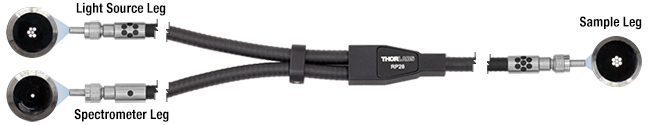 |
 |
| RP21 | ||
| RP30 | 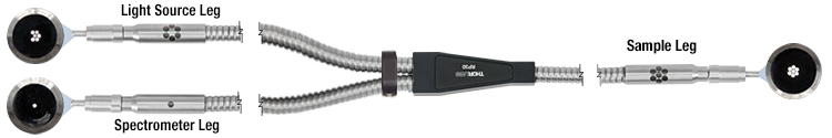 |
|
| Item # | Hydroxyl Content |
Wavelength Range |
Fiber Item # |
Jacket Item # |
Light Source Leg |
Sample Leg |
Spectrometer Leg |
Fiber Core Diameter |
Fiber Cladding Diameter |
NA | Min Bend Radius | Fiber Attenuation Plot |
|
|---|---|---|---|---|---|---|---|---|---|---|---|---|---|
| Short Term |
Long Term |
||||||||||||
| RP20a | High OH | 250 - 1200 nmb | FG200UEA | FT061PS | SMA Connector, Round |
SMA Connector |
SMA Connector, Single Fiber |
200 ± 4 µm | 220 ± 2 µm | 0.22 ± 0.02c | 23 mmd | 46 mmd | |
| RP21a | Low OH | 400 - 2400 nm | FG200LEA | ||||||||||
| RP30e | - | 285 - 4500 nmf | ZBLANg Multimode |
FT080SSh | 200 ± 10 µm | 290 ± 10 µm | 0.20 ± 0.02 @ 2 µmc |
140 mm ± 30 mmi | |
||||
The RP28 and RP29 reflection probes feature a spectrometer leg with a linear bundle configuration for improved coupling efficiency with our compact spectrometers. The linear bundle end matches the shape of the entrance slit better than a single fiber or round bundle configuration, increasing the amount of light entering the device (see the Round vs Linear Leg tab for more information). This is ideal for samples that are sensitive to light exposure or heating caused by absorption. The light source end consists of a single fiber; this can be useful when a sample's exposure to light needs to be minimized.
When plugging the linear end of the bundle cable into the spectrometer or other device, the fiber array must be aligned with the entrance slit. For ease of alignment, the fiber array's axis is indicated by a line on the connector sleeve, as shown to the right. Precise alignment of the bundle and slit is not critical, but misalignment of more than ±5° can cause a reduction in signal strength. In order to maximize signal intensity, we recommend rotating the bundle while monitoring light levels in the spectrometer; once optimized, tighten down the threaded portion of the SMA connector to lock the bundle in place. When using these bundles with our CCD Compact Spectrometers, the fiber array should be oriented vertically.
Each connector is engraved with the fiber output configuration in that leg.
| Item # | Fiber Configurations | ||
|---|---|---|---|
| RP28 | 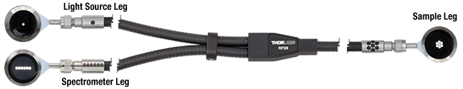 |
 |
|
| RP29 | |||
| Item #a | Hydroxyl Content |
Wavelength Range |
Fiber Item # |
Jacket Item # |
Light Source Leg |
Sample Leg |
Spectrometer Leg |
Fiber Core Diameter |
Fiber Cladding Diameter |
NA | Min Bend Radius | Fiber Attenuation Plot |
||||
|---|---|---|---|---|---|---|---|---|---|---|---|---|---|---|---|---|
| Short Term | Long Term | |||||||||||||||
| RP28 | High OH | FG200UEA | FT061PS | SMA Connector, Single Fiber |
SMA Connector |
SMA Connector, Linear Bundle |
23 mmd | 46 mmd | |
|||||||
| RP29 | Low OH | 400 - 2400 nm | FG200LEA | |||||||||||||
Each SMA connector is engraved with the fiber output configuration for that leg. Please note that the exact position of the dark fiber used as a spacer in the light source leg is not guaranteed. For the MIR fiber bundle, the dark fiber will never be in the center of the light source leg.
When choosing between bundles that use low-OH silica fiber, high-OH silica fiber, or ZBLAN MIR fiber, it is important to consider the attenuation performance in the wavelength range of interest as all three fiber types
| Item # | Fiber Configurations | ||
|---|---|---|---|
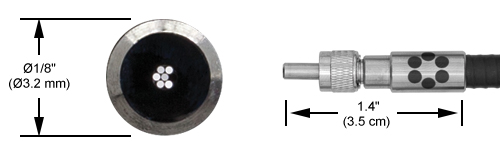
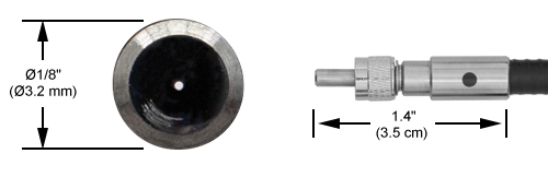
| RP22 | 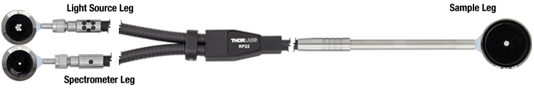 |
|
|
| RP23 | |||
| RP31 | 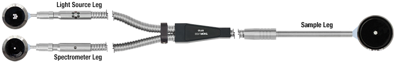 |
||
| Item # | Hydroxyl Content |
Wavelength Range |
Fiber Item # |
Jacket Item # |
Light Source Leg |
Sample Leg |
Spectrometer Leg |
Fiber Core Diameter |
Fiber Cladding Diameter |
NA | Min Bend Radius | Fiber Attenuation Plot |
|
|---|---|---|---|---|---|---|---|---|---|---|---|---|---|
| Short Term |
Long Term |
||||||||||||
| RP22a | High OH | 250 - 1200 nmb | FG200UEA | FT061PS | SMA Connector, Round Bundle |
Ø1/4" Probec |
SMA Connector, Single Fiber |
200 ± 4 µm | 220 ± 2 µm | 0.22 ± 0.02d | 23 mme | 46 mme | |
| RP23a | Low OH | 400 - 2400 nm | FG200LEA | ||||||||||
| RP31f | - | 285 - 4500 nmg | ZBLANh Multimode |
FT080SSi | 200 ± 10 µm | 290 ± 10 µm | 0.20 ± 0.02 @ 2 µmd |
140 mm ± 30 mmj | |
||||
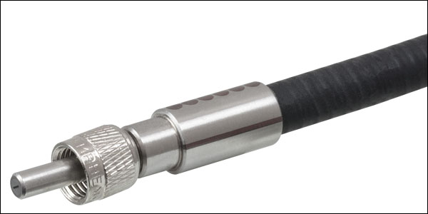
Click to Enlarge
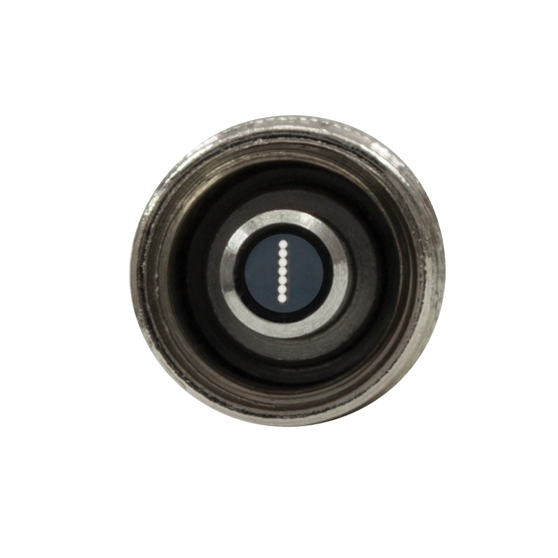
Spectrometer End Alignment Engraving
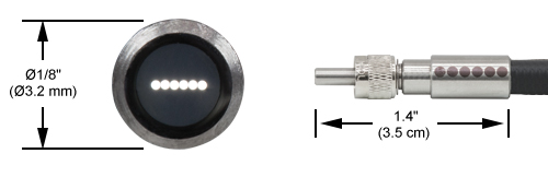
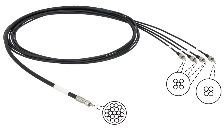
The RP24 and RP25 reflection probes feature a spectrometer leg with a linear bundle configuration for improved coupling efficiency with our compact spectrometers. The linear bundle end matches the shape of the entrance slit better than a single fiber or round bundle configuration, increasing the amount of light entering the device (see the Round vs Linear Leg tab for more information). This is ideal for samples that are sensitive to light exposure or heating caused by absorption. The light source end consists of a single fiber; this can be useful when a sample's exposure to light needs to be minimized.
When plugging the linear end of the bundle cable into the spectrometer or other device, the fiber array must be aligned with the entrance slit. For ease of alignment, the fiber array's axis is indicated by a line on the connector sleeve, as shown to the right. Precise alignment of the bundle and slit is not critical, but misalignment of more than ±5° can cause a reduction in signal strength. In order to maximize signal intensity, we recommend rotating the bundle while monitoring light levels in the spectrometer; once optimized, tighten down the threaded portion of the SMA connector to lock the bundle in place. When using these bundles with our CCD Compact Spectrometers, the fiber array should be oriented vertically.
Each SMA connector is engraved with the fiber output configuration for that leg.
| Item # | Fiber Configurations | ||
|---|---|---|---|
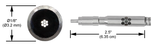
| RP24 | 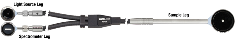 |
|
|
| RP25 | |||
| Item #a | Hydroxyl Content |
Wavelength Range |
Fiber Item # |
Light Source Leg |
Sample Leg |
Spectrometer Leg |
Fiber Core Diameter |
Fiber Cladding Diameter |
NA | Minimum Bend Radius | Fiber Attenuation Plot |
||||
|---|---|---|---|---|---|---|---|---|---|---|---|---|---|---|---|
| Short Term | Long Term | ||||||||||||||
| RP24 | High OH | 250 - 1200 nmb | FG200UEA | SMA Connector, Single Fiber |
Ø1/4" Probec |
SMA Connector, Linear Bundle |
200 ± 4 µm | 220 ± 2 µm | 0.22 ± 0.02d | 23 mme | 46 mme | |
|||
| RP25 | Low OH | 400 - 2400 nm | FG200LEA | ||||||||||||

 Zoom
Zoom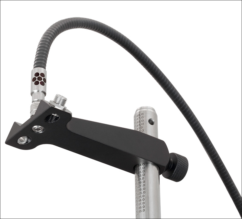
Click to Enlarge
Underside of the RPA-SMA Fiber Holder Arm
Click to Enlarge
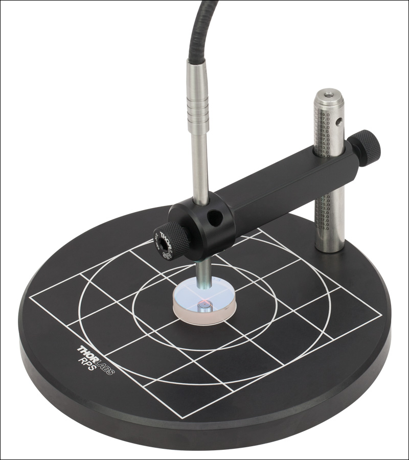
Specular Reflectance Measurements at 90°
Click to Enlarge
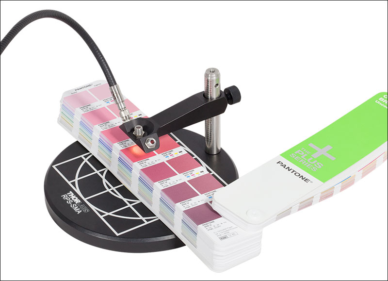
Diffuse Reflectance Measurements at 45°
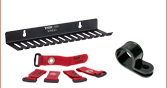
- Securely Hold Fiber Optic Probes with Ø1/4" Probe or SMA-Connectorized Sample Leg
- Orient Fiber Probe at 90° or 45° with Respect to the Sample
- Adjustable Height Arm Accommodates Samples up to at least 2.16" (55 mm) Tall
- Ø6" (Ø152.4 mm) Base with Engraved Grid and Concentric Circles
- Replacement Arm Assemblies Also Available
Thorlabs' RPS and RPS-SMA Adjustable Fiber Optic Probe Stands are designed to hold Ø1/4" or SMA-connectorized fiber bundle probes (respectively) above a sample at 45° for diffuse measurements or 90° for specular measurements. Each set is comprised of an adjustable fiber holder arm (also available separately), a Ø1/2" optical post with engraved metric height scale, and a Ø6" (Ø152.4 mm) base with engraved concentric circles and grid pattern. The 90° mount of the RPS-SMA stand and RPA-SMA arm places the end of the probe flush with the bottom of the arm, allowing it to be in direct contact with the sample, as seen in the photo to the far right; the arm also features twin 45° mounting bulkheads that allow two separate fiber patch cables to be used for specular reflection measurements with a 45° angle of incidence (AOI).
Sample legs with Ø1/4" probes are held in place on the RPA arm using a TS25H thumbscrew, while SMA-connectorized sample ends screw into the bulkheads on the RPA-SMA arm. Each arm's height can be adjusted using a TS25H thumbscrew, which has a spring-loaded, retractable Delrin®* tip. The spring-loaded tip provides sufficient force to hold the arm in place as final positional adjustments are being made, allowing for precise height adjustments. When using the RPS stand, samples up to 2.16" (55 mm) tall can be accommodated using the included optical post. The RPS-SMA stand can accommodate samples up to 2.36" (60 mm) tall. For taller samples, the included post can be easily replaced with a longer imperial or metric Ø1/2" post. The post is secured to the base by an M6 cap screw on the underside of the base, which can be removed using a 3/16" or 5 mm balldriver. If replacing the original post with an imperial Ø1/2" post, a SH25S063 1/4"-20 cap screw is also required.
Replacement RPA and RPA-SMA post holder arms are also available separately. These arms can also be used to mount Ø1/4" probes or SMA-connectorized optical fiber within custom optomechanical setups by mounting them to Ø1/2" posts.
*Delrin® is a registered trademark of DuPont Polymers, Inc.

 Zoom
Zoom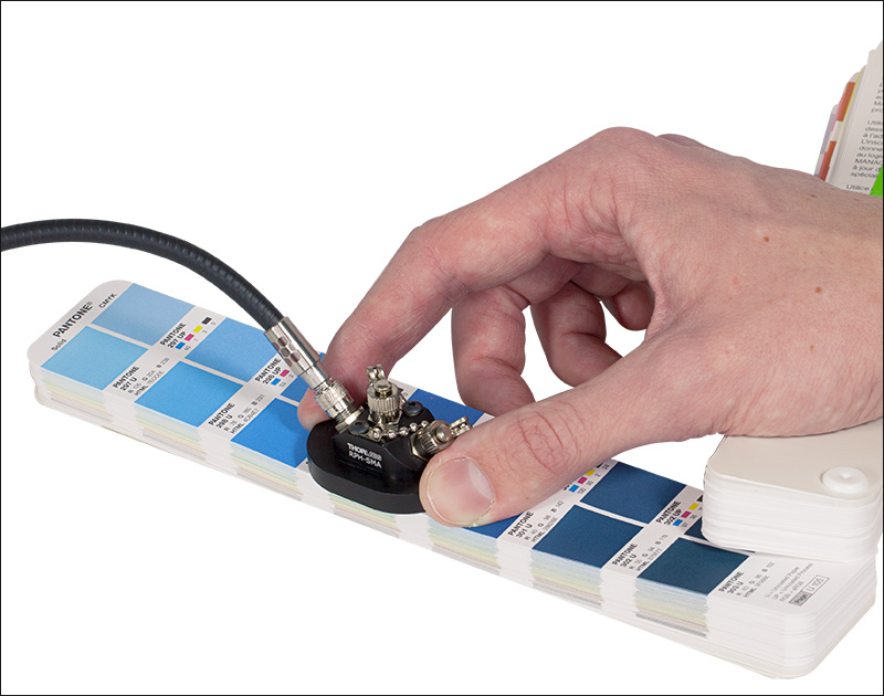
Click to Enlarge
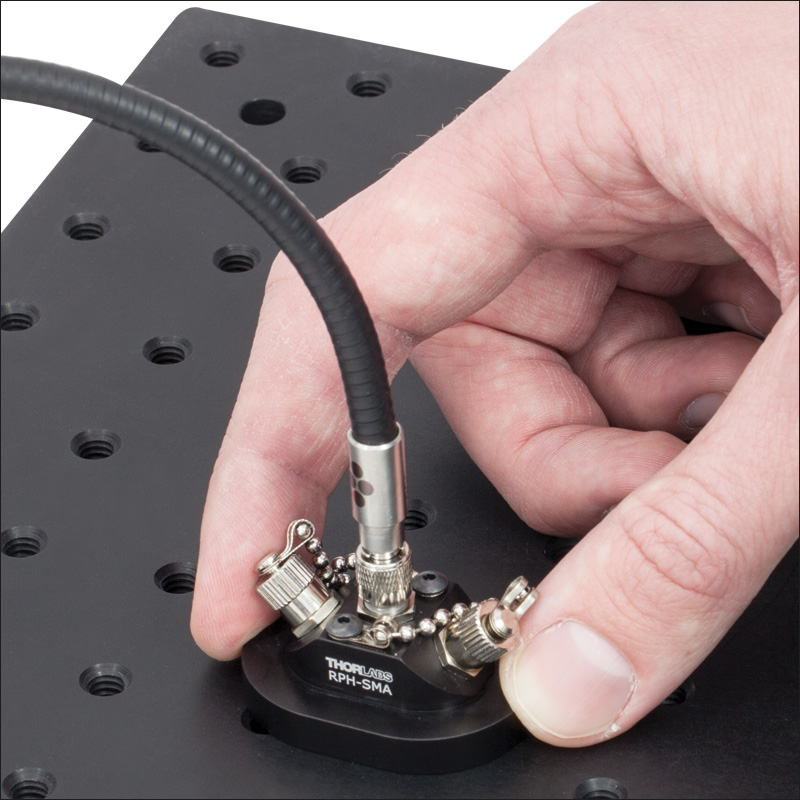
Diffuse Reflectance Measurement Using an RPH-SMA Mount
Click to Enlarge
Specular Reflectance Measurement Using an RPH Ø1/4" Probe Holder
Click to Enlarge
Schematic of the RPH
- Secure Fiber Optic Probes at 90° or 45° with Respect to the Sample
- Take Reflectivity and Color Measurements of Flat Surfaces by Placing Holder Block Directly on Sample
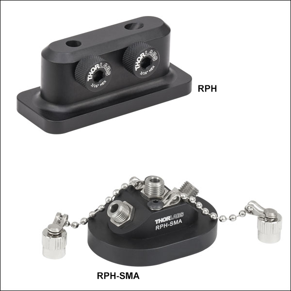
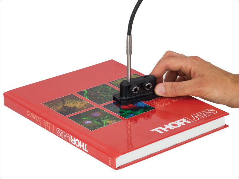
The RPH Holder Block for Ø1/4" Fiber Optic Probes allows a fiber bundle tip to be placed directly above a sample. Background light may be blocked by covering the bore that is not in use with masking tape. Two ports are available for securing the probe at 45° or 90° with respect to the sample. The probe can be secured at various heights using one of two TS25H thumbscrews. The probe tip should never be inserted all the way through the block or flush with the bottom of the block, as any contact with the sample can result in damage to the fiber end face.
The RPH-SMA Holder Block for Fiber Optic Probes allows a fiber tip with an SMA905 connector to be placed 0.48" (12 mm) from a sample while subsequently blocking out background light. To use, place the RPH-SMA directly on a flat sample, with the exit port on the bottom of the unit (visible in the photo above) over the area to be measured. The block has three SMA connector bulkheads and two removable CAPN1 bulkhead caps (additional caps sold below). These caps can be used to cover the unused SMA ports during a measurement to block stray room light. In addition, the twin 45° mounting bulkheads allow two separate fiber patch cables to be used for specular reflection measurements with a 45° angle of incidence (AOI).
On both of the holder blocks, the 45° and the 90° ports share a common exit hole, as illustrated in the schematic of the RPH and the photo of the underside of the RPH-SMA above.