Broadband Polarizing Beamsplitter Cubes

- Available in Sizes Ranging From 5 mm to 2" (50.8 mm)
- Reflects S Polarization by 90°
- Five Wavelength Ranges Available
PBS102
(10 mm)
PBS253
(1")
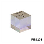
PBS201
(20 mm)
PBS054
(5 mm)
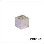
PBS122
(1/2")
1" Beamsplitter Cube Mounted on a KM100P Platform Mount with a PM4 Clamping Arm
PBS513
(2")

Please Wait
Click to Enlarge
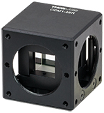
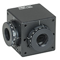
12.7 mm Beamsplitter Cube Mounted in the CCM1-4ER Compact Cage Cube Using the BS127CAM Beamsplitter Adapter
(Refer to the BS Cube Mounting tab for Other Options)
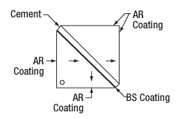
Cube Beamsplitter Diagram
(Coating and Cement Layer Not to Scale)
Features
- 5 mm, 10 mm, 1/2" (12.7 mm), 20 mm, 1" (25.4 mm), and 2" (50.8 mm) Cubes
- Five Wavelength Ranges Available:
- 420 - 680 nm
- 620 - 1000 nm
- 700 - 1300 nm
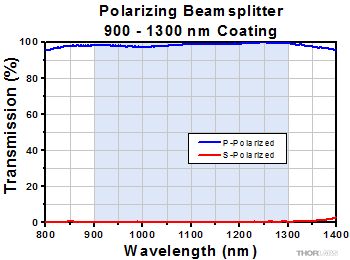
- 900 - 1300 nm
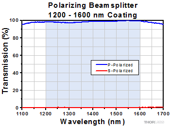
- 1200 - 1600 nm
- Extinction Ratio
- PBS519: Average TP:TS > 1000:1
- All Other Beamsplitters Below: TP:TS > 1000:1
Thorlabs' Polarizing Beamsplitting Cubes are offered in six sizes and with five beamsplitting coating ranges. These cubes separate the s- and p-polarization components by reflecting the s component with the dielectric beamsplitter coating, while allowing the p component to pass. These cubes are designed to be used with the transmitted beam, which offers an extinction ratio of TP:TS > 1000:1, except the PBS519 2" 420 - 680 nm cube, which offers an average extinction ratio of > 1000:1 over the wavelength range. The reflected beam will only have an extinction ratio of roughly 20:1 to 100:1, depending on the beamsplitter.
Thorlabs offers polarizing beamsplitter cubes in 5 mm, 10 mm, 1/2" (12.7 mm), 20 mm, 1" (25.4 mm), and 2" (50.8 mm) sizes. These cubes are made from N-SF1 or
H-ZF3 glass and are offered in five different coatings for the following wavelength ranges: 420 - 680 nm, 620 - 1000 nm, 700 - 1300 nm, 900 - 1300 nm, and 1200 - 1600 nm. Please see the Specs tab for more information on each cube, including its damage threshold, or see the Graphs tab for S- and P-polarization transmission graphs.
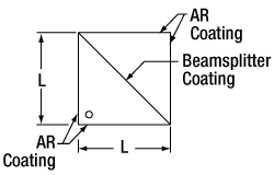
The dielectric beamsplitting coating is applied to the hypotenuse of one of the two prisms that make up the cube. Then, cement is used to bind the two prism halves together (refer to the diagram shown above). The engraved dot on the top of the cube indicates the prism with the beamsplitting coating. Light can be input into any of the polished faces to separate the S and P polarizations. Cubes larger than 5 mm also feature engraved arrows indicating one possible orientation.
Please refer to the BS Cube Mounting tab above for information on mounting options and compatibility. Alternatively, our 1" cubes are available pre-mounted in cage cubes. Custom beamsplitter cubes can be ordered by contacting Technical Support. For high power applications, we offer high power polarizing beamsplitting cubes. We also offer polarizing beamsplitter cubes at laser line wavelengths, which have an extinction ratio of 3000:1 (TP:TS). Polyhedron broadband polarizing beamsplitters with high extinction ratios up to 100 000:1, high damage thresholds, and low-GDD are also available.
| Beamsplitter Cube Size | 5 mm Cube | 10 mm Cube | 1/2" (12.7 mm) Cube | 20 mm Cube | 1" (25.4 mm) Cube | 2" (50.8 mm) Cube |
|---|---|---|---|---|---|---|
| Wavelength Ranges Available |
420 - 680 nm 620 - 1000 nm 700 - 1300 nm 900 - 1300 nm 1200 - 1600 nm |
|||||
| Dimensional Tolerance | +0 / -0.2 mm | |||||
| Material | N-SF1 | |||||
| Extinction Ratioa | TP:TS > 1000:1 | PBS519: TP:TS Average > 1000:1 PBS512: TP:TS > 1000:1 PBS515: TP:TS > 1000:1 PBS513: TP:TS > 1000:1 PBS514: TP:TS > 1000:1 |
||||
| Transmission Efficiency | TP > 90% | PBS519: TP, Avg > 85%b PBS512: TP > 90% PBS515: TP > 90% PBS513: TP > 90% PBS514: TP > 90% |
||||
| Reflection Efficiency | RS, Avg > 95% | PBS519: RS, Avg > 93%b PBS512: RS, Avg > 95% PBS515: RS, Avg > 95% PBS513: RS, Avg > 95% PBS514: RS, Avg > 95% |
||||
| Transmitted Beam Deviation | 0° ± 5 arcmin | |||||
| Reflected Beam Deviation | 90° ± 5 arcmin | |||||
| Clear Aperture | >3.5 mm x 3.5 mm | >8.0 mm x 8.0 mm | >10.16 mm x 10.16 mm | >16.0 mm x 16.0 mm | >20.32 mm x 20.32 mm | PBS519: >40.64 mm x 40.64 mm PBS512: >45.72 mm x 45.72 mm PBS515: >45.7 mm x 45.7 mm PBS513: >45.72 mm x 45.72 mm PBS514: >45.72 mm x 45.72 mm |
| Transmitted Wavefront Error | <λ/4 @ 633 nm (Over Ø3.5 mm) |
<λ/4 @ 633 nm (Over Ø8.0 mm) |
<λ/4 @ 633 nm (Over Ø10.16 mm) |
<λ/4 @ 633 nm (Over Ø16.0 mm) |
<λ/4 @ 633 nm (Over Ø20.32 mm) |
<λ/2 @ 633 nmc |
| Surface Quality | 40-20 Scratch-Dig | |||||
| Coating Range | AR Coating Reflectancea | Damage Thresholdb | |
|---|---|---|---|
| 420 - 680 nm | Ravg < 0.5% | CWc | 350 W/cm at 532 nm, Ø1.000 mm |
| Pulsed | 2 J/cm2 at 532 nm, 10 ns, 10 Hz | ||
| 620 - 1000 nm | CWc | 50 W/cm at 810 nm, Ø0.019 mm | |
| Pulsed | 2 J/cm2 at 810 nm, 10 ns, 10 Hz | ||
| 700 - 1300 nm | Ravg < 1% | - | |
| 900 - 1300 nm | Ravg < 0.5% | CWc,d | 1000 W/cm at 1070 nm, Ø0.971 mm |
| Pulsed | 2 J/cm2 at 1064 nm, 10 ns, 10 Hz | ||
| 1200 - 1600 nm | CWc,d | 1000 W/cm at 1540 nm, Ø1.030 mm | |
| Pulsed | 5 J/cm2 at 1542 nm, 10 ns, 10 Hz | ||
| Coating Range | Damage Thresholda | |
|---|---|---|
| 420 - 680 nm | CWb | 350 W/cm at 532 nm, Ø1.000 mm |
| Pulsed | 2 J/cm2 at 532 nm, 10 ns, 10 Hz | |
| 620 - 1000 nm | CWb | 50 W/cm at 810 nm, Ø0.019 mm |
| Pulsed | 2 J/cm2 at 810 nm, 10 ns, 10 Hz | |
| 900 - 1300 nm | CWb,c | 1000 W/cm at 1070 nm, Ø0.971 mm |
| Pulsed | 2 J/cm2 at 1064 nm, 10 ns, 10 Hz | |
| 1200 - 1600 nm | CWb,c | 1000 W/cm at 1540 nm, Ø1.030 mm |
| Pulsed | 5 J/cm2 at 1542 nm, 10 ns, 10 Hz | |
Damage Threshold Data for Thorlabs' Polarizing Beamsplitter Cubes
The specifications to the right are measured data for Thorlabs' polarizing beamsplitter cubes. Damage threshold specifications are constant for a given wavelength range, regardless of the size of the beamsplitter.
Laser Induced Damage Threshold Tutorial
The following is a general overview of how laser induced damage thresholds are measured and how the values may be utilized in determining the appropriateness of an optic for a given application. When choosing optics, it is important to understand the Laser Induced Damage Threshold (LIDT) of the optics being used. The LIDT for an optic greatly depends on the type of laser you are using. Continuous wave (CW) lasers typically cause damage from thermal effects (absorption either in the coating or in the substrate). Pulsed lasers, on the other hand, often strip electrons from the lattice structure of an optic before causing thermal damage. Note that the guideline presented here assumes room temperature operation and optics in new condition (i.e., within scratch-dig spec, surface free of contamination, etc.). Because dust or other particles on the surface of an optic can cause damage at lower thresholds, we recommend keeping surfaces clean and free of debris. For more information on cleaning optics, please see our Optics Cleaning tutorial.
Testing Method
Thorlabs' LIDT testing is done in compliance with ISO/DIS 11254 and ISO 21254 specifications.
First, a low-power/energy beam is directed to the optic under test. The optic is exposed in 10 locations to this laser beam for 30 seconds (CW) or for a number of pulses (pulse repetition frequency specified). After exposure, the optic is examined by a microscope (~100X magnification) for any visible damage. The number of locations that are damaged at a particular power/energy level is recorded. Next, the power/energy is either increased or decreased and the optic is exposed at 10 new locations. This process is repeated until damage is observed. The damage threshold is then assigned to be the highest power/energy that the optic can withstand without causing damage. A histogram such as that below represents the testing of one BB1-E02 mirror.
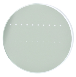
The photograph above is a protected aluminum-coated mirror after LIDT testing. In this particular test, it handled 0.43 J/cm2 (1064 nm, 10 ns pulse, 10 Hz, Ø1.000 mm) before damage.
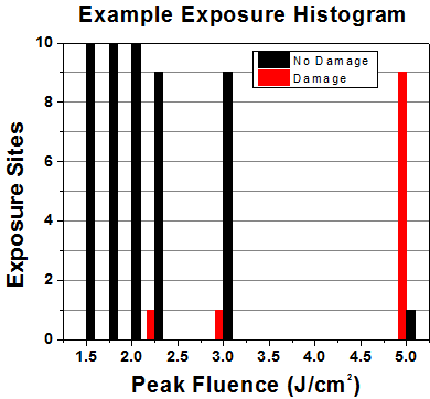
| Example Test Data | |||
|---|---|---|---|
| Fluence | # of Tested Locations | Locations with Damage | Locations Without Damage |
| 1.50 J/cm2 | 10 | 0 | 10 |
| 1.75 J/cm2 | 10 | 0 | 10 |
| 2.00 J/cm2 | 10 | 0 | 10 |
| 2.25 J/cm2 | 10 | 1 | 9 |
| 3.00 J/cm2 | 10 | 1 | 9 |
| 5.00 J/cm2 | 10 | 9 | 1 |
According to the test, the damage threshold of the mirror was 2.00 J/cm2 (532 nm, 10 ns pulse, 10 Hz, Ø0.803 mm). Please keep in mind that these tests are performed on clean optics, as dirt and contamination can significantly lower the damage threshold of a component. While the test results are only representative of one coating run, Thorlabs specifies damage threshold values that account for coating variances.
Continuous Wave and Long-Pulse Lasers
When an optic is damaged by a continuous wave (CW) laser, it is usually due to the melting of the surface as a result of absorbing the laser's energy or damage to the optical coating (antireflection) [1]. Pulsed lasers with pulse lengths longer than 1 µs can be treated as CW lasers for LIDT discussions.
When pulse lengths are between 1 ns and 1 µs, laser-induced damage can occur either because of absorption or a dielectric breakdown (therefore, a user must check both CW and pulsed LIDT). Absorption is either due to an intrinsic property of the optic or due to surface irregularities; thus LIDT values are only valid for optics meeting or exceeding the surface quality specifications given by a manufacturer. While many optics can handle high power CW lasers, cemented (e.g., achromatic doublets) or highly absorptive (e.g., ND filters) optics tend to have lower CW damage thresholds. These lower thresholds are due to absorption or scattering in the cement or metal coating.

LIDT in linear power density vs. pulse length and spot size. For long pulses to CW, linear power density becomes a constant with spot size. This graph was obtained from [1].
Pulsed lasers with high pulse repetition frequencies (PRF) may behave similarly to CW beams. Unfortunately, this is highly dependent on factors such as absorption and thermal diffusivity, so there is no reliable method for determining when a high PRF laser will damage an optic due to thermal effects. For beams with a high PRF both the average and peak powers must be compared to the equivalent CW power. Additionally, for highly transparent materials, there is little to no drop in the LIDT with increasing PRF.
In order to use the specified CW damage threshold of an optic, it is necessary to know the following:
- Wavelength of your laser
- Beam diameter of your beam (1/e2)
- Approximate intensity profile of your beam (e.g., Gaussian)
- Linear power density of your beam (total power divided by 1/e2 beam diameter)
Thorlabs expresses LIDT for CW lasers as a linear power density measured in W/cm. In this regime, the LIDT given as a linear power density can be applied to any beam diameter; one does not need to compute an adjusted LIDT to adjust for changes in spot size, as demonstrated by the graph to the right. Average linear power density can be calculated using the equation below.

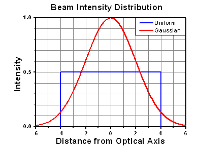
The calculation above assumes a uniform beam intensity profile. You must now consider hotspots in the beam or other non-uniform intensity profiles and roughly calculate a maximum power density. For reference, a Gaussian beam typically has a maximum power density that is twice that of the uniform beam (see lower right).
Now compare the maximum power density to that which is specified as the LIDT for the optic. If the optic was tested at a wavelength other than your operating wavelength, the damage threshold must be scaled appropriately. A good rule of thumb is that the damage threshold has a linear relationship with wavelength such that as you move to shorter wavelengths, the damage threshold decreases (i.e., a LIDT of 10 W/cm at 1310 nm scales to 5 W/cm at 655 nm):

While this rule of thumb provides a general trend, it is not a quantitative analysis of LIDT vs wavelength. In CW applications, for instance, damage scales more strongly with absorption in the coating and substrate, which does not necessarily scale well with wavelength. While the above procedure provides a good rule of thumb for LIDT values, please contact Tech Support if your wavelength is different from the specified LIDT wavelength. If your power density is less than the adjusted LIDT of the optic, then the optic should work for your application.
Please note that we have a buffer built in between the specified damage thresholds online and the tests which we have done, which accommodates variation between batches. Upon request, we can provide individual test information and a testing certificate. The damage analysis will be carried out on a similar optic (customer's optic will not be damaged). Testing may result in additional costs or lead times. Contact Tech Support for more information.
Pulsed Lasers
As previously stated, pulsed lasers typically induce a different type of damage to the optic than CW lasers. Pulsed lasers often do not heat the optic enough to damage it; instead, pulsed lasers produce strong electric fields capable of inducing dielectric breakdown in the material. Unfortunately, it can be very difficult to compare the LIDT specification of an optic to your laser. There are multiple regimes in which a pulsed laser can damage an optic and this is based on the laser's pulse length. The highlighted columns in the table below outline the relevant pulse lengths for our specified LIDT values.
Pulses shorter than 10-9 s cannot be compared to our specified LIDT values with much reliability. In this ultra-short-pulse regime various mechanics, such as multiphoton-avalanche ionization, take over as the predominate damage mechanism [2]. In contrast, pulses between 10-7 s and 10-4 s may cause damage to an optic either because of dielectric breakdown or thermal effects. This means that both CW and pulsed damage thresholds must be compared to the laser beam to determine whether the optic is suitable for your application.
| Pulse Duration | t < 10-9 s | 10-9 < t < 10-7 s | 10-7 < t < 10-4 s | t > 10-4 s |
|---|---|---|---|---|
| Damage Mechanism | Avalanche Ionization | Dielectric Breakdown | Dielectric Breakdown or Thermal | Thermal |
| Relevant Damage Specification | No Comparison (See Above) | Pulsed | Pulsed and CW | CW |
When comparing an LIDT specified for a pulsed laser to your laser, it is essential to know the following:
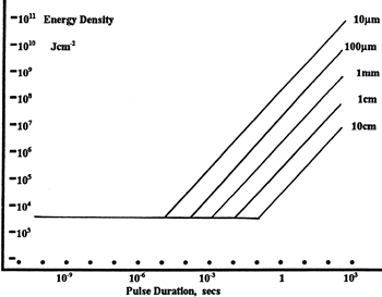
LIDT in energy density vs. pulse length and spot size. For short pulses, energy density becomes a constant with spot size. This graph was obtained from [1].
- Wavelength of your laser
- Energy density of your beam (total energy divided by 1/e2 area)
- Pulse length of your laser
- Pulse repetition frequency (prf) of your laser
- Beam diameter of your laser (1/e2 )
- Approximate intensity profile of your beam (e.g., Gaussian)
The energy density of your beam should be calculated in terms of J/cm2. The graph to the right shows why expressing the LIDT as an energy density provides the best metric for short pulse sources. In this regime, the LIDT given as an energy density can be applied to any beam diameter; one does not need to compute an adjusted LIDT to adjust for changes in spot size. This calculation assumes a uniform beam intensity profile. You must now adjust this energy density to account for hotspots or other nonuniform intensity profiles and roughly calculate a maximum energy density. For reference a Gaussian beam typically has a maximum energy density that is twice that of the 1/e2 beam.
Now compare the maximum energy density to that which is specified as the LIDT for the optic. If the optic was tested at a wavelength other than your operating wavelength, the damage threshold must be scaled appropriately [3]. A good rule of thumb is that the damage threshold has an inverse square root relationship with wavelength such that as you move to shorter wavelengths, the damage threshold decreases (i.e., a LIDT of 1 J/cm2 at 1064 nm scales to 0.7 J/cm2 at 532 nm):

You now have a wavelength-adjusted energy density, which you will use in the following step.
Beam diameter is also important to know when comparing damage thresholds. While the LIDT, when expressed in units of J/cm², scales independently of spot size; large beam sizes are more likely to illuminate a larger number of defects which can lead to greater variances in the LIDT [4]. For data presented here, a <1 mm beam size was used to measure the LIDT. For beams sizes greater than 5 mm, the LIDT (J/cm2) will not scale independently of beam diameter due to the larger size beam exposing more defects.
The pulse length must now be compensated for. The longer the pulse duration, the more energy the optic can handle. For pulse widths between 1 - 100 ns, an approximation is as follows:

Use this formula to calculate the Adjusted LIDT for an optic based on your pulse length. If your maximum energy density is less than this adjusted LIDT maximum energy density, then the optic should be suitable for your application. Keep in mind that this calculation is only used for pulses between 10-9 s and 10-7 s. For pulses between 10-7 s and 10-4 s, the CW LIDT must also be checked before deeming the optic appropriate for your application.
Please note that we have a buffer built in between the specified damage thresholds online and the tests which we have done, which accommodates variation between batches. Upon request, we can provide individual test information and a testing certificate. Contact Tech Support for more information.
[1] R. M. Wood, Optics and Laser Tech. 29, 517 (1998).
[2] Roger M. Wood, Laser-Induced Damage of Optical Materials (Institute of Physics Publishing, Philadelphia, PA, 2003).
[3] C. W. Carr et al., Phys. Rev. Lett. 91, 127402 (2003).
[4] N. Bloembergen, Appl. Opt. 12, 661 (1973).
In order to illustrate the process of determining whether a given laser system will damage an optic, a number of example calculations of laser induced damage threshold are given below. For assistance with performing similar calculations, we provide a spreadsheet calculator that can be downloaded by clicking the button to the right. To use the calculator, enter the specified LIDT value of the optic under consideration and the relevant parameters of your laser system in the green boxes. The spreadsheet will then calculate a linear power density for CW and pulsed systems, as well as an energy density value for pulsed systems. These values are used to calculate adjusted, scaled LIDT values for the optics based on accepted scaling laws. This calculator assumes a Gaussian beam profile, so a correction factor must be introduced for other beam shapes (uniform, etc.). The LIDT scaling laws are determined from empirical relationships; their accuracy is not guaranteed. Remember that absorption by optics or coatings can significantly reduce LIDT in some spectral regions. These LIDT values are not valid for ultrashort pulses less than one nanosecond in duration.

A Gaussian beam profile has about twice the maximum intensity of a uniform beam profile.
CW Laser Example
Suppose that a CW laser system at 1319 nm produces a 0.5 W Gaussian beam that has a 1/e2 diameter of 10 mm. A naive calculation of the average linear power density of this beam would yield a value of 0.5 W/cm, given by the total power divided by the beam diameter:

However, the maximum power density of a Gaussian beam is about twice the maximum power density of a uniform beam, as shown in the graph to the right. Therefore, a more accurate determination of the maximum linear power density of the system is 1 W/cm.
An AC127-030-C achromatic doublet lens has a specified CW LIDT of 350 W/cm, as tested at 1550 nm. CW damage threshold values typically scale directly with the wavelength of the laser source, so this yields an adjusted LIDT value:

The adjusted LIDT value of 350 W/cm x (1319 nm / 1550 nm) = 298 W/cm is significantly higher than the calculated maximum linear power density of the laser system, so it would be safe to use this doublet lens for this application.
Pulsed Nanosecond Laser Example: Scaling for Different Pulse Durations
Suppose that a pulsed Nd:YAG laser system is frequency tripled to produce a 10 Hz output, consisting of 2 ns output pulses at 355 nm, each with 1 J of energy, in a Gaussian beam with a 1.9 cm beam diameter (1/e2). The average energy density of each pulse is found by dividing the pulse energy by the beam area:

As described above, the maximum energy density of a Gaussian beam is about twice the average energy density. So, the maximum energy density of this beam is ~0.7 J/cm2.
The energy density of the beam can be compared to the LIDT values of 1 J/cm2 and 3.5 J/cm2 for a BB1-E01 broadband dielectric mirror and an NB1-K08 Nd:YAG laser line mirror, respectively. Both of these LIDT values, while measured at 355 nm, were determined with a 10 ns pulsed laser at 10 Hz. Therefore, an adjustment must be applied for the shorter pulse duration of the system under consideration. As described on the previous tab, LIDT values in the nanosecond pulse regime scale with the square root of the laser pulse duration:

This adjustment factor results in LIDT values of 0.45 J/cm2 for the BB1-E01 broadband mirror and 1.6 J/cm2 for the Nd:YAG laser line mirror, which are to be compared with the 0.7 J/cm2 maximum energy density of the beam. While the broadband mirror would likely be damaged by the laser, the more specialized laser line mirror is appropriate for use with this system.
Pulsed Nanosecond Laser Example: Scaling for Different Wavelengths
Suppose that a pulsed laser system emits 10 ns pulses at 2.5 Hz, each with 100 mJ of energy at 1064 nm in a 16 mm diameter beam (1/e2) that must be attenuated with a neutral density filter. For a Gaussian output, these specifications result in a maximum energy density of 0.1 J/cm2. The damage threshold of an NDUV10A Ø25 mm, OD 1.0, reflective neutral density filter is 0.05 J/cm2 for 10 ns pulses at 355 nm, while the damage threshold of the similar NE10A absorptive filter is 10 J/cm2 for 10 ns pulses at 532 nm. As described on the previous tab, the LIDT value of an optic scales with the square root of the wavelength in the nanosecond pulse regime:

This scaling gives adjusted LIDT values of 0.08 J/cm2 for the reflective filter and 14 J/cm2 for the absorptive filter. In this case, the absorptive filter is the best choice in order to avoid optical damage.
Pulsed Microsecond Laser Example
Consider a laser system that produces 1 µs pulses, each containing 150 µJ of energy at a repetition rate of 50 kHz, resulting in a relatively high duty cycle of 5%. This system falls somewhere between the regimes of CW and pulsed laser induced damage, and could potentially damage an optic by mechanisms associated with either regime. As a result, both CW and pulsed LIDT values must be compared to the properties of the laser system to ensure safe operation.
If this relatively long-pulse laser emits a Gaussian 12.7 mm diameter beam (1/e2) at 980 nm, then the resulting output has a linear power density of 5.9 W/cm and an energy density of 1.2 x 10⁻⁴ J/cm2 per pulse. This can be compared to the LIDT values for a WPQ10E-980 polymer zero-order quarter-wave plate, which are 5 W/cm for CW radiation at 810 nm and 5 J/cm2 for a 10 ns pulse at 810 nm. As before, the CW LIDT of the optic scales linearly with the laser wavelength, resulting in an adjusted CW value of 6 W/cm at 980 nm. On the other hand, the pulsed LIDT scales with the square root of the laser wavelength and the square root of the pulse duration, resulting in an adjusted value of 55 J/cm2 for a 1 µs pulse at 980 nm. The pulsed LIDT of the optic is significantly greater than the energy density of the laser pulse, so individual pulses will not damage the wave plate. However, the large average linear power density of the laser system may cause thermal damage to the optic, much like a high-power CW beam.
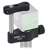
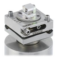
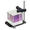
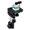
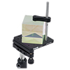
Thorlabs offers a variety of mounting solutions for our beamsplitter cubes. The mounts below allow our cubes to be post-mounted or integrated into our 16 mm or 30 mm cage systems. Post-mountable solutions are compatible with our Ø1/2" Posts as well as Ø1" Posts with 8-32 (M4) taps.
| Post-Mountable Mounts for Beamsplitter Cubes | ||||||||
|---|---|---|---|---|---|---|---|---|
| Click Photo to Enlarge (Cubes Not Included) |
 |
 |
 |
 |
 |
 |
 |
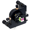 |
| Item # | PCM(/M) | BSH10(/M) BSH05(/M) BSH20(/M) BSH1(/M) BSH2(/M) |
FBTB(/M) | KM100PM(/M) | KM200PM(/M) | KM100B(/M) | KM200B(/M) | K6XS |
| Required Accessories | Base: PCMP(/M) | - | - | Clamp: PM3(/M) or PM4(/M) |
Clamp: PM3(/M) or PM4(/M) |
Clamp: PM3(/M) or PM4(/M) |
Clamp: PM3(/M) or PM4(/M) |
Adapter: K6A1(/M) |
| Mounting Options | Ø1/2" Posts | Ø1/2" Postsa,b | Ø1/2" Posts | Ø1/2" Posts | Ø1/2" Posts | Ø1/2" Posts | Ø1/2" Posts | Ø1/2" Posts |
| Features | Compact | Compact | Glue-In Mount with Precision Tip, Tilt, and Rotation | Tip and Rotation | Tip and Rotation | Kinematic Mount | Kinematic Mount | 6-Axis Mount |
| Compatible Beamsplitter Cube Size(s) |
Up to 20 mm | 10 mm, 1/2", 20 mm, 1", 2" |
5 mm | Up to 20 mmc Up to 1" d |
Up to 20 mmc Up to 1" d Up to 2" e |
Up to 20 mmc Up to 1" d |
Up to 20 mmc Up to 1" d Up to 2" e |
5 mm 10 mm 1/2" |
| Cage System Mounts for Beamsplitter Cubes | |||||||||
|---|---|---|---|---|---|---|---|---|---|
| Click Photo to Enlarge (Cubes Not Included) |
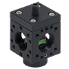 |
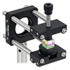 |
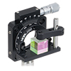 |
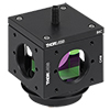 |
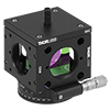 |
 |
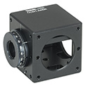 |
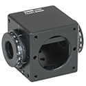 |
 |
| Item # | Cage Cube: SC6W |
ARV1 | CRM1(/M) or CRM1P(/M) | Cage Cube: C4W or C6W a | CCM1-4ER(/M) | CCM1-A4ER(/M) | CCM1-B4ER(/M) | CCM1-C4ER(/M) | |
| Required Accessories | Clamp: SB6C, Platform: SPM2 |
- | Adapter: K6A1(/M) |
Clamp: B6C, Platform: B3C(/M) or B4C(/M) |
Clamp: B6C, Platform: B3CR(/M) or B4CRP(/M) |
- | - | - | - |
| Mounting Options |
16 mm Cage Systems | 30 mm Cage Systems | 30 mm Cage Systems or Ø1/2" Posts | 30 mm Cage Systems | 30 mm Cage Systems or Ø1/2" Posts | ||||
| Features | Compact | Compact | Rotation Mount | Fixed or Kinematic Platforms | Rotation Platforms | - | One Rotation Mount | Two Rotation Mounts @ 180° | Two Rotation Mounts @ 90° |
| Compatible Beamsplitter Cube Size(s) |
10 mm | 5 mm 10 mm |
5 mm 10 mm 1/2" |
1/2" 20 mm 1" |
5 mm (with BS5CAM Adapter) 10 mm (with BS10CAM Adapter) 1/2" (with BS127CAM Adapter) 20 mm (with BS20CAM Adapter) 1" (Directly Compatible) |
||||
Beamsplitter Selection Guide
Thorlabs' portfolio contains many different kinds of beamsplitters, which can split beams by intensity or by polarization. We offer plate and cube beamsplitters, though other form factors exist, including pellicle and birefringent crystal. For an overview of the different types and a comparison of their features and applications, please see our overview. Many of our beamsplitters come in premounted or unmounted variants. Below is a complete listing of our beamsplitter offerings. To explore the available types, wavelength ranges, splitting/extinction ratios, transmission, and available sizes for each beamsplitter category, click More [+] in the appropriate row below.Plate Beamsplitters
| Non-Polarizing Plate Beamsplitters |
|---|
| Polarizing Plate Beamsplitters |
|---|
Cube Beamsplitters
| Non-Polarizing Cube Beamsplitters |
|---|
| Polarizing Cube and Polyhedron Beamsplitters |
|---|
| Type | Wavelength Range | Extinction Ratio (TP:TS) |
Typical Transmission | AR Coated Faces |
Cemented | Available Cube/ Polyhedron Side Length |
| Standard: Unmounted 16 mm Cage Cube 30 mm Cage Cube |
420 - 680 nm | >1000:1 | Yes | Yes | Unmounted: 5 mm, 10 mm, 1/2", 20 mm, 1", and 2" Mounted: 20 mm in a 16 mm Cage Cube, 1" in a 30 mm Cage Cube |
|
| 620 - 1000 nm | ||||||
| 700 - 1300 nm | ||||||
| 900 - 1300 nm | ||||||
| 1200 - 1600 nm | ||||||
| Wire Grid: Unmounted 30 mm Cage Cube |
400 - 700 nm | >1000:1 (AOI: 0° - 5°) >100:1 (AOI: 0° - 25°) |
P-Pol. S-Pol. |
Yes | Yes | Unmounted: 1" Mounted: 20 mm in a 16 mm Cage Cube, 1" in a 30 mm Cage Cube |
| High-Power Laser Line: Unmounted 30 mm Cage Cube |
355 nm | >2000:1 | No | Unmounted: 1/2" and 1" Mounted: 1" in a 30 mm Cage Cube |
||
| 405 nm | ||||||
| 532 nm | ||||||
| 633 nm | ||||||
| 780 - 808 nm | ||||||
| 1064 nm | ||||||
| Laser Line: Unmounted 30 mm Cage Cube |
532 nm | >3000:1 | Yes | Yes | Unmounted: 10 mm, 1/2", and 1" Mounted: 1" in a 30 mm Cage Cube |
|
| 633 nm | ||||||
| 780 nm | ||||||
| 980 nm | ||||||
| 1064 nm | ||||||
| 1550 nm | ||||||
| High-Power, Broadband, High Extinction Ratio Polarizers | 700 - 1100 nm | >1000:1 (700 - 1100 nm) >5000:1 (750 - 1000 nm) >10 000:1 (800 - 900 nm) |
Yes | No | 12.7 mm (Input/Output Face, Square) |
|
| 900 - 1300 nm | >1000:1 (900 - 1300 nm) >10 000:1 (900 - 1250 nm) >100 000:1 (980 - 1080 nm) |
10.0 mm and 5.0 mm (Input/Output Face, Square) |
||||
| Laser-Line Variable | 532 nm | Not Specified | No Graph Available | Yes | Yes | Assembly Mounted in a 30 mm Cage Cube |
| 633 nm | ||||||
| 780 nm | ||||||
| 1064 nm | ||||||
| 1550 nm | ||||||
| Broadband Variable | 420 - 680 nm | Not Specified | No Graph Available | Yes | Yes | Assembly Mounted in a 30 mm Cage Cube |
| 690 - 1000 nm | ||||||
| 900 - 1200 nm | ||||||
| 1200 - 1600 nm | ||||||
| Circular Polarizer/Beamsplitter |
532 nm | Not Specified | No Graph Available | Yes | Yes | Assembly Mounted in a 30 mm Cage Cube |
| 633 nm | ||||||
| 780 nm | ||||||
| 1064 nm | ||||||
| 1550 nm |
Pellicle Beamsplitters
| Non-Polarizing Pellicle Beamsplitters |
|---|
Crystal Beamsplitters
| Polarizing Crystal Beamsplitters |
|---|
Other
| Other Beamsplitters |
|---|
Polarizer Selection Guide
Thorlabs offers a diverse range of polarizers, including wire grid, film, calcite, alpha-BBO, rutile, and beamsplitting polarizers. Collectively, our line of wire grid polarizers offers coverage from the visible range to the beginning of the Far-IR range. Our nanoparticle linear film polarizers provide extinction ratios as high as 100 000:1. Alternatively, our other film polarizers offer an affordable solution for polarizing light from the visible to the Near-IR. Next, our beamsplitting polarizers allow for use of the reflected beam, as well as the more completely polarized transmitted beam. Finally, our alpha-BBO (UV), calcite (visible to Near-IR), rutile (Near-IR to Mid-IR), and yttrium orthovanadate (YVO4) (Near-IR to Mid-IR) polarizers each offer an exceptional extinction ratio of 100 000:1 within their respective wavelength ranges.
To explore the available types, wavelength ranges, extinction ratios, transmission, and available sizes for each polarizer category, click More [+] in the appropriate row below.
| Wire Grid Polarizers |
|---|
| Film Polarizers |
|---|
| Beamsplitting Polarizers |
|---|
| Polarizer Type | Wavelength Range | Extinction Ratio | Transmissiona | Available Sizes |
| Polarizing Plate Beamsplitters | 405 nm | >10 000:1 | Ø1" and 25 mm x 36 mm | |
| 532 nm | ||||
| 633 nm | ||||
| 780 nm | ||||
| 808 nm | ||||
| 1030 nm | ||||
| 1064 nm | ||||
| 1310 nm | ||||
| 1550 nm | ||||
| Polarizing Bandpass Filters | 355 nm +6 nm / -9 nm | 1 000 000:1 | 25.2 mm x 35.6 mm | |
| Broadband Polarizing Beamsplitter Cubes (Unmounted, 16 mm Cage Cube, or 30 mm Cage Cube) |
420 nm - 680 nm | 1000:1e | 5 mm, 10 mm, 1/2", 20 mmf, 1"f, and 2" | |
| 620 nm - 1000 nm | ||||
| 700 nm - 1300 nm | ||||
| 900 nm - 1300 nm | ||||
| 1200 nm - 1600 nm | ||||
| Wire Grid Polarizing Beamsplitter Cubes (Unmounted or 30 mm Cage Cube) |
400 nm - 700 nm | >1 000:1 (AOI: 0° - 5°) >100:1 (AOI: 0° - 25°) |
P-Pol. S-Pol. |
1"f |
| Laser-Line Polarizing Beamsplitter Cubes (Unmounted or 30 mm Cage Cube) |
532 nm | 3000:1 | 10 mm, 1/2", 1"f | |
| 633 nm | ||||
| 780 nm | ||||
| 980 nm | 1"f | |||
| 1064 nm | 10 mm, 1/2", 1"f | |||
| 1550 nm | ||||
| High-Power Laser-Line Polarizing Beamsplitter Cubes (Unmounted or 30 mm Cage Cube) | 355 nm | 2000:1 | 1/2" and 1"f | |
| 405 nm | ||||
| 532 nm | ||||
| 633 nm | ||||
| 780 - 808 nm | ||||
| 1064 nm | ||||
| High-Power, Broadband, High Extinction Ratio Polarizers | 700 nm - 1100 nm | > 1000:1 (700 - 1100 nm) > 5000:1 (750 - 1000 nm) > 10 000:1 (800 - 900 nm) |
12.7 mm (Input/Output Face, Square) |
|
| 900 nm - 1300 nm | >1000:1 (900 - 1300 nm) >10 000:1 (900 - 1250 nm) >100 000:1 (980 - 1080 nm) |
10 mm and 5 mm (Input/Output Face, Square) |
||
| Calcite Beam Displacers | 350 nmg - 2.3 µm (Uncoated) | - | 10 mmb (Clear Aperture, Square) |
|
| Yttrium Orthovanadate (YVO4) Beam Displacers | 488 nm - 3.4 µm (Uncoated) | - | >3 mm x 5 mm Ellipseh (Clear Aperture) |
|
| 2000 nm (V Coated) |
| alpha-BBO Polarizers |
|---|
| Calcite Polarizers |
|---|
| Quartz Polarizers |
|---|
| Magnesium Fluoride Polarizers |
|---|
| Yttrium Orthovanadate (YVO4) Polarizers |
|---|
| Rutile Polarizers |
|---|
Insights into Polarization Conventions
Scroll down to read about:
- Labels Used to Identify Perpendicular and Parallel Components
Click here for more insights into lab practices and equipment.
Labels Used to Identify Perpendicular and Parallel Components
When polarized light is incident on a surface, it is often described in terms of perpendicular and parallel components. These are orthogonal to each other and the direction in which the light is propagating (Figure 1).
Labels and symbols applied to the perpendicular and parallel components can make it difficult to determine which is which. The table identifies, for a variety of different sets, which label refers to the perpendicular component and which to the parallel.
| Labels | Notes |
|
|---|---|---|
| Perpendicular | Parallel | |
| s | p | Senkrecht (s) is 'perpendicular' in German. Parallel begins with 'p.' |
| TE | TM | TE: Transverse electric field. |
| ⊥ | // | ⊥ and // are symbols for perpendicular and parallel, respectively. |
| σ | π | The Greek letters corresponding to s and p are σ and π, respectively. |
| Sagittal | Tangential | A sagittal plane is a longitudinal plane that divides a body. |
The perpendicular and parallel directions are referenced to the plane of incidence, which is illustrated in Figure 1 for a beam reflecting from a surface. Together, the incident ray and the surface normal define the plane of incidence, and the incident and reflected rays are both contained in this plane. The perpendicular direction is normal to the plane of incidence, and the parallel direction is in the plane of incidence.
The electric fields of the perpendicular and parallel components oscillate in planes that are orthogonal to one another. The electric field of the perpendicular component oscillates in a plane perpendicular to the plane of incidence, while the electric field of the parallel component oscillated in the plane of incidence. The polarization of the light beam is the vector sum of the perpendicular and parallel components.
Normally Incident Light
Since a plane of incidence cannot be defined for normally incident light, this approach cannot be used to unambiguously define perpendicular and parallel components of light. There is limited need to make the distinction, since under conditions of normal incidence the reflectivity is the same for all components of light.
Date of Last Edit: Mar. 5, 2020
| Posted Comments: | |
user
(posted 2023-09-17 22:45:40.243) Dear Thorlabs,
We discovered what might seem to be a discrepancy with regards to transmission of PBS 251 at 405 nm. Raw data specified on your website suggests the T should exceed ~88%.
Could you look into it? We would also like to receive the transmission and reflection vs. AOI dependency for different polarizations.
Thank you.
Best regards,
Ian cdolbashian
(posted 2023-09-25 09:41:55.0) Thank you for contacting Thorlabs! The wavelength range available of PBS251 is 420-680nm, the raw data shown on website is typical and the transmission performance outside the coating area will vary from lot to lot, so the transmission difference at 405nm is normal. We have some data for different AOI and will send it to you via email. user
(posted 2023-08-22 17:41:36.28) Hello, can you share the zemax file or membrane file of PBS203? cdolbashian
(posted 2023-08-30 09:56:08.0) Thank you for reaching out to us with this inquiry. Unfortunately, we do not have a Zemax file to share with you. I have contacted you directly to discuss your application. Perhaps there is something alternative which we can share. Clemens Alt
(posted 2023-03-22 11:27:25.38) Hi Thorlabs team,
It's a bit surprising that only the large (1") polarizing beam splinters are available with 700-1300 nm coating. It would be very useful if the small ones (1/2" and smaller) were also made available with that coating.
The tuning range of femtosecond lasers is increasing. E.g. I am looking to combine a fixed 1045 nm beam with a beam that is tunable from 680 -1300. A large beam splitter cube just adds an unnecessary length of glass.
All the best! cdolbashian
(posted 2023-04-04 11:14:45.0) Thank you for contacting Thorlabs! We can provide the 1/2'' or smaller beam splitter with 700-1300nm coating as a special one. I'll reach out to you directly to discuss your application. Petr Bouchal
(posted 2022-06-15 13:35:28.833) Hello Thorlabs, I am interested in the extinction ratio of broadband polarizing cubes at wavelength 425 nm, or any advice on which of your polarizers performs best at this wavelength. Thanks, Petr cdolbashian
(posted 2022-06-17 04:51:40.0) Thank you for reaching out to us Petr. The extinction ratio you can expect for these cubes, within the operating range specified, will be ~1000:1. This is specified in the specs tab above, and you can see the graphical representation of the transmission and reflected percentages in the Graphs tab, as well as the raw data (link located in each caption). I have reached out to you directly to discuss the various catalogue options we have for polarizing optics. Ha Chang Kyun
(posted 2022-01-26 02:27:58.413) Hello thorlabs. Can you send me input beam angle dependency of polarizing beam spliter transmission/reflection ? jgreschler
(posted 2022-01-27 12:46:18.0) Thank you for reaching out to Thorlabs. You can request additional data on our products by contacting our Tech Support team at techsupport@thorlabs.com. I have reached out directly to provide the AOI data requested. Zhan Tianpeng
(posted 2021-12-14 16:10:55.003) 可以看看关于PBS251的波长在400-900nm之内的曲线吗?关于它的R和T曲线 YLohia
(posted 2021-12-14 01:28:08.0) Hello, thank you for contacting Thorlabs. An applications engineer from our team in China (techsupport-cn@thorlabs.com) will discuss this directly with you. Eric Copenhaver
(posted 2021-08-04 14:59:45.973) There is a spec for the Polarization Extinction Ratio on the transmitted port, i.e. Tp/Ts ~ 30 dB. There is a reflection efficiency for s polarization, Rs, but it would also be very helpful to know what to expect as the PER on the reflected beam (even if the recommendation is to only use the transmitted beam for high PER). Even just a typical number would be good to know. From experience it seems close to ~20:1, 13 dB. YLohia
(posted 2021-08-05 01:22:05.0) Thank you for contacting Thorlabs. Unfortunately, we do not have a specification on the extinction ratio of reflected beam at the moment. The typical value of PER on the reflected beam depends on product type. If you are interested in a specific part number, our Solutions Team (techsales@thorlabs.com) can look into arranging a tested special for a measured reflected PER upon request at an added cost. BANG-YU HSU
(posted 2020-04-21 13:42:59.773) Is it possible to purchase this broadband PBS cube working from 400 nm to 1100 nm like your AB-coating? You currently only have two separated ranges, 420-680 and 620-1000 nm . YLohia
(posted 2020-04-22 08:21:44.0) Thank you for contacting Thorlabs. Custom optics can be requested by emailing techsupport@thorlabs.com. I have reached out to you directly to discuss the possibility of offering this. Chris Pinyan
(posted 2019-12-31 11:15:32.757) can we have log graphs for he S curve so we can see extinction ratio? nbayconich
(posted 2020-01-16 10:50:18.0) Thank you for your feedback. I have forwarded your suggestion to our marketing team. A log scale plot similar to our nanoparticle polarizer transmission & E.R. plots would be much easier to observe the extinction ratio of each beamsmplitter. In the meantime the raw data provided on our webpage can be used to make a log scale plot. Sebastian Fava
(posted 2019-11-29 15:11:26.923) From what I see, you only have coatings which are reflecting s-polirized light and the transmitting p-polirized.
In our setup, we combine two beams with different polirizations (around 1.5 um, 100 fs pulses, 100 kHz repetition rate), and to do so we need to reflect the p-polirized coming from the left and transmit the s-porized.
We can rotate the beam with half wave plates, but this reduces the intensity, and if we rotate the cube we reflect the beam in the direction perpendicular to the plane instead.
Do you have cubes with coatings reflecting the p-polirized light instead? Or can you suggest similar products? nbayconich
(posted 2019-12-05 03:09:06.0) Thank you for contacting Thorlabs. At the moment we do not have polarizing beamsplitters designed to reflect the P polarization state. Our quartz waveplates however can achieve close to >99% transmission which would be the simplest alternative to searching for this particular type of polarizing beamsplitter. David R
(posted 2019-09-30 16:54:36.593) Hello. I am interested in knowing the phase that the PBS252 introduces on vertically polarized light, which is reflected on the PBS, relative to the horizontally polarized component, which is transmitted. Have you measured it? If yes, could you provide me with that data? If no, do you know if it is possible to measure it? nbayconich
(posted 2019-10-10 09:17:00.0) Thank you for contacting Thorlabs. Unfortunately we do not have this information at the moment regarding the effective phase shift of a reflected or transmitted beam. The phase change can be measured with an ellipsometer. amihaybazak
(posted 2018-11-26 12:59:37.68) I am interested in below product. Please send me incident angle dependency of the Polarization transmission and reflection. We need upto +/- 25 degree incident angle. PBS251 25.4 mm Polarizing Beamsplitter Cube, 420 - 680 nm YLohia
(posted 2018-11-27 08:32:24.0) Hello, thank you for contacting Thorlabs. I have reached out to you directly with this information. yongqi.shi
(posted 2018-11-16 13:25:46.467) Hey, why there are some line diffracted pattern after the PBS cube when a gaussian beam penetrating through? nbayconich
(posted 2018-11-19 02:13:31.0) Thank you for contacting Thorlabs. Would it be possible to provide more details about your current setup such as operating wavelength, any additional optics used, etc? If there are any backreflections re-entering either face of the beamsplitter this could cause an interference pattern. I will contact you directly to help troubleshoot this problem you are seeing. gennady.s.sarkisov
(posted 2018-10-09 16:21:24.417) What R and T for 532nm and 1064nm for PBS252 ??? YLohia
(posted 2018-10-10 10:44:22.0) Hello, thank you for contacting Thorlabs. Based on some scans we have performed, we expect the following out-of-band performance with these units:
532nm -> R: 68.44% (s-Pol) 0.28% (p-Pol); T: 8.41% (s-Pol) 80.15% (p-Pol)
1064nm -> R: 96.32% (s-Pol) 0.59% (p-Pol); T: 0.32% (s-Pol) 95.81% (p-Pol) Mark.O.Brown
(posted 2018-04-19 20:13:49.47) Hello,
Your page on Glan-Taylor polarizers inlcudes a helpful "field-of-view" discussion & plot. I assume that there's some dependence for these PBSs as well? In which case it would be nice to have this info here.
All the best,
Mark nbayconich
(posted 2018-04-23 09:33:15.0) Thank you for contacting Thorlabs. Yes the transmission and reflectance performance of the PBS cubes will have a dependence on the angle of incident on the beamsplitter coating. I'll reach out to you directly with additional data regarding the performance at various AOI's. ksuwer
(posted 2018-04-12 18:24:13.403) I'm using 780nm LASER and i mistakenly bought PBS253, not buying PBS252. can i use PBS253 with 780nm LASER? can i know the spec of PBS253 at 780nm wavelength? YLohia
(posted 2018-04-16 03:37:05.0) Hello, thank you for contacting Thorlabs. Unfortunately, we don't have a spec for PBS253 at 780nm since this is outside the beamsplitter coating range. The split ratio will not be ideal and the will also be loss in transmission due to the difference in AR coating range. I will reach out to you directly to look into the possibility of a return in exchange for PBS252. fangjian.wang
(posted 2018-03-02 14:29:14.96) Hallo,
could I heat the PBS104 upto 90°C for several minutes? YLohia
(posted 2018-04-03 09:38:11.0) Hello, thank you for contacting Thorlabs. Heating the PBS104 up to 90°C will be fine. Please note that you should not exceed 100°C for any duration of time. eilon.poem
(posted 2018-02-13 03:52:27.707) Dear Thorlabs,
We're interested in a PBS with the same spectral transmission/reflection as the PBS051 (specifically, good performance at both 404 nm and 808 nm), just made of fused silica, as the N-SF1 glass fluoresces quite badly when excited by 404 nm light. Any other glass with suppressed fluorescence (at least 50 fold suppression with respect to N-SF1) would also do.
Would you be able to find us such a product?
Thanks,
Eilon and Xin-Bing YLohia
(posted 2018-03-29 02:05:50.0) Dear Eilon and Xin-Bing, thank you for contacting Thorlabs. We will reach out to you directly regarding the possibility of offering this custom item. If simultaneous use of 404nm and 808nm light is not required, you can look into our "High Power Laser Line Polarizing Beamsplitter Cubes" that can be found on this page: https://www.thorlabs.com/newgrouppage9.cfm?objectgroup_id=6055. These are made of UV Fused Silica. jysohn
(posted 2018-01-23 08:26:57.54) I am interested in below two products.
Please send me incident angle dependency of the Polarization transmission and reflection.
We need upto +/- 15 degree incident angle.
Jin
PBS101 10 mm Polarizing Beamsplitter Cube, 420 - 680 nm
PBS201 20 mm Polarizing Beamsplitter Cube, 420 - 680 nm nbayconich
(posted 2018-01-25 09:57:01.0) Thank you for contacting Thorlabs. I will contact you directly with additional AOI data for the PBS101 & PBS201. cohennc
(posted 2017-08-16 16:26:12.217) can you send me data on the 900-1300
what is the Transmission and reflectibity in 650nm+635nm
thanks
Nissim tfrisch
(posted 2017-08-30 03:01:19.0) Hello, thank you for contacting Thorlabs. Unfortunately, the cubes designed at 900-1300nm will not be suitable around 650nm. The exact transmissions for S and P states will vary from one lot to another. I will reach out to you directly to discuss your application. vksaini
(posted 2017-07-21 11:27:14.56) Dear Sir/Madam
My laser beam is exactly two inch diameter in round shape and i have to use the polariser intra-cavity for that i need Polarising cube beam splitter of size slightly more than (2"). Could you supply the same, if yes at what cost. Do you any have indian agent.
03 Nos is required in 500-600 nm wavelength range with Tp:Ts extintion ratio at least 1000:1 tfrisch
(posted 2017-07-26 01:16:23.0) Hello, thank you for contacting Thorlabs. I will reach out to you directly regarding a quote for these. user
(posted 2017-06-20 09:53:56.503) Hello,
In the product overview section, you write:
"Light can be input into any of the polished faces to separate the s- and p-polarizations. However, for best performance, the light should enter through one of the entrance faces of the coated prism, which are indicated by a dot."
However, it is unclear what is meant by "for best performance". I am sending laser light on two cascaded PBSs. On the first PBS the light is incident on the dotted prism, so the transmitted light is p-polarized with high purity. On the second PBS, the light is incident on the non-dotted prism, and ~10% of the light is reflected, despite the high purity. Is this normal behavior? Can it still be claimed that either facet can be used to separate polarizations?
I am trying to combine two beams of orthogonal polarization into a single beam. In this case it is inevitable that one beam will enter the non-dotted prism. I don't want to lose 10% of the light. Can you recommend a different product?
I am using 1550nm light.
Thank you very much. tfrisch
(posted 2017-06-27 10:19:59.0) Hello, thank you for contacting Thorlabs. There are two different effects happening here. First, the not about optimal performance concerns the manufacturing method. At the beamsplitting interface, there is a beamsplitter coating as well as cement that holds the two halves together. They are designed such that the light should be reflected off of the coating before passing through the cement, but this is negligible in most applications. As for the 10% reflectance, that is normal. The high purity of the transmitted beam is achieved by maximizing the reflectance of the S state. This minimizes the transmission of the S state so that the transmission is almost entirely P- polarized. However, the reflected state has a significant reflectance for the P state (about 10% as you note). Please reach out to TechSupport@Thorlabs.com to further discuss your application and the sources you are looking to combine. john.kirtley
(posted 2017-05-03 18:47:06.983) Hello,
I am wondering if the 420-680 nm cube will also reflect light at 785 nm. The graph shows still relatively decent beam splitting at 785 nm, so while the P polarized light is transmitted, I am wondering if the S-polarized light is reflected at 785nm. Thanks. tfrisch
(posted 2017-05-19 02:07:08.0) Hello, thank you for contacting Thorlabs. As seen on the Graphs tab, there is a significant transmission bump in the S state in the NIR. Because of this the PER will be greatly reduced. However, absorption would be low, so the non-transmitted component of the S state would be reflected, yes. I will reach out to you directly to discuss your application. kc636
(posted 2016-03-24 09:28:52.423) Do you have a beamsplitter that would work in the 1600-2200nm range?
Alternatively, what is the performance of PBS124 at 1800nm? besembeson
(posted 2016-03-24 02:35:47.0) Response from Bweh at Thorlabs USA: You may want to consider the Glan-Taylor (http://www.thorlabs.us/newgrouppage9.cfm?objectgroup_id=816) or Glan-Laser (http://www.thorlabs.us/newgrouppage9.cfm?objectgroup_id=815) polarizers, whose un-coated versions can be used over a broader spectrum. The polarizing beam splitter coatings generally perform poorly outside the designed spectral range so the PBS124 will not be suitable around 1800nm. joachim.fischer
(posted 2015-01-20 09:47:30.947) Dear Thorlabs team,
do you have (numerical) data for phase vs. wavelength of the reflected beam available? That would be very interesting for me. I'm especially interested in the PBS121.
Joe besembeson
(posted 2015-03-27 10:46:04.0) Response from Bweh at Thorlabs USA: We do not have this data at this time. y.jin
(posted 2014-10-24 14:54:12.527) I would like to ask if I could also use PBS102 as a beam combiner? What about the polarization states of two beams at the output?
Thanks
Yuwei besembeson
(posted 2014-10-30 05:18:07.0) Response from Bweh at Thorlabs USA: Yes you could use this as a beam combiner although we don't have test data yet for this orientation. We expect the polarization states of both beams to stay the same during and after combination. In terms of the expected output power, note that the transmission efficiency of the beamsplitter coating for the p-polarized state is >90% and the reflection efficiency for s-polarized light is >99.5%. dmahler
(posted 2014-04-07 15:07:44.713) What spec (if any) is there for the amount of wedge in the glue used to hold the two prisms together? I am measuring an optical path difference of around 10 microns for two beams entering the beamsplitter about 2mm apart, and am trying to rule out wedge in the beamsplitter.
Thanks, cdaly
(posted 2014-04-09 04:19:18.0) Response from Chris at Thorlabs: We do not have a specification for the wedge angle created by the epoxied surfaced between the prisms. We do however specify a transmitted beam deviated spec to be <5armin. Depending on the deviation along with the incident angle of the beam, this could account for the observed path length difference. leaf
(posted 2014-01-21 09:50:36.73) I am looking for a PBS for both 1064 and 1550 nm wavelengths. Which coating would work better, the 900-1300 nm or the 1200-1600 nm. Spectral plots for both coatings at 1064 and 1550 nm would be very useful. jlow
(posted 2014-01-27 01:56:59.0) Response from Jeremy at Thorlabs: Neither polarizing beamsplitter cube would work at both 1064 and 1550nm. The performance of these beamsplitter cube falls off rapidly outside the specified range. We might have an alternative for you depending on your requirements. I will contact you directly to discuss about your application,. anton.tau
(posted 2014-01-14 15:18:52.86) We bought Polarizing Beamsplitter Cube (PBS054) at Thorlabs 18 Sep 2013 web order acknowledgement WEB N6W421935. Number on the package W006430.
We have installed it into the optical scheme and discovered some strange behavior. The beam that passes through the cube deviates greatly in the plane parallel to the base of the cube. We estimate the deviation to be ~11 degrees, too far from the quoted (<5 arcmin) value. What could be the reason for this?
Best regards,
Anton Tausenev.
Atseva LLC
950 52 ave ct T-4
Greeley, CO, 80634
tel: 970-396-6189
fax: 877-656-6643
www.atseva.com jlow
(posted 2014-01-15 08:23:09.0) Response from Jeremy at Thorlabs: We will contact you directly to troubleshoot this. user
(posted 2013-11-07 19:31:17.093) According to specs tab, PBS can withstand 10,000 W/cm.
It seems quite high damage threshold.
Is it true? tcohen
(posted 2013-11-07 03:53:53.0) Response from Tim at Thorlabs: With a focused spot diameter of 18um, the PBS053 showed no damage with an exposure duration of a minute on 20 separate sites with a power exceeding 10000 W/cm at 1064 nm, Ø0.018 mm. Although we would expect this linear power density to remain constant for an increased beam size, a larger beam is more likely to land on a damage precursor (such as a surface defect), and thus cause damage. ajh
(posted 2013-10-30 17:29:04.08) Could you give a number for the percentage of reflectivity of the AR-coatings at 632nm? In other words, how much ghost reflections does one get at 90degree incidence? tcohen
(posted 2013-11-07 03:43:35.0) Response from Tim at Thorlabs: Each outer optical surface is BBAR coated. The spec within the coating region is Ravg<0.5% at normal angle of incidence. Each surface will have this spec and so you can use this to calculate first back reflection and any ghost reflections after splitting for an approximation of ghost beams. asvaghos.a
(posted 2013-08-09 06:34:11.04) I happened to drop my PBS253 cube to ground. I check it and the beam splitting coating surface doesnt seem to blur or turn intransparent. But however if there is an SOP to check if It still work at least as good as before? jlow
(posted 2013-08-14 14:01:00.0) Response from Jeremy at Thorlabs: We will contact you directly to check the condition of your PBS253. jlow
(posted 2012-08-08 16:50:00.0) Response from Jeremy at Thorlabs: The difference between the beamsplitters for different wavelength ranges are mainly the AR coating and the beamsplitter coating. The performance for out-of-band wavelength cannot be guaranteed. dominic.siriani
(posted 2012-08-08 09:09:50.0) Is the difference between the wavelength ranges on the polarizing beam splitters only the AR coatings on the cube faces? If the 1200-1600 nm splitter were used at ~900 nm, would the transmission extinction ratio still be Tp:Ts > 1000:1? tcohen
(posted 2012-07-03 10:37:00.0) Response from Tim at Thorlabs: Thank you for your inquiry. The design wavelength of the PBS051 is 420nm-680nm. Even with an AR coating of 400nm-700nm, the beamsplitter coating would be out of the specified band. To change the design wavelength would involve creating a custom coating, which would include engineering costs and coating production costs. We offer N-BK7, UVFS, CAF2, ZnSe and Ge right angle prisms. I would like to discuss with you the requirements of your system to provide the best options for your application and I will contact you directly to continue this conversation. joekkrause
(posted 2012-06-28 23:39:17.0) How much would it cost for you to make a custom cube of N-SF1 with an AR coating for the 400-700 nm range? Also do you offer any right angle prisms made of N-SF1? tcohen
(posted 2012-05-16 16:43:00.0) Response from Tim at Thorlabs: Thank you for your feedback! The wavefront distortion is for both the transmitted and reflected beam. We will update our web presentation with this information. ahambi
(posted 2012-05-15 03:51:16.0) Is the wavefront distortion $ \lambda/4 $ also for the reflected beam? tcohen
(posted 2012-03-01 10:54:00.0) Response from Tim at Thorlabs: Thank you for your feedback on the PBS251. It is difficult to produce exact damage thresholds because of the many variables involved. For CW, usually damage occurs first in the substrate. However, surface irregularities in the optic can also play a role. The intensity profile of your beam will also have an influence on a CW LIDT. As an estimate, we advise not using over 13W/cm^2 CW for this product. However, because LIDT decreases with an increase in frequency, the threshold will be lower for your lower wavelength. I have contacted you directly to find out more information on your setup. utsavdeepak.dave
(posted 2012-02-29 09:55:44.0) Hi, I would like to know the damage threshold for the PBS251 product used with blue light (464 nm, CW). bdada
(posted 2011-10-06 20:21:00.0) Response from Buki at Thorlabs:
Thank you for your feedback. What you may be experiencing is the magneto optical Kerr effect - where the polarization of light changes when it interacts with magnetized media. We think the coating and not the material is what is being magnetized and causing the reflected/transmitted beams to be altered. This magnetization will change as the external magnetic field changes, explaining why the unbalance changes at the same frequency as the rotation of the magnetic field.
Please contact TechSupport@thorlabs.com if you want to discuss this further. nmandal
(posted 2011-09-28 15:56:42.0) Should the intensities of the two beams coming out of the PBS change in presence of magnetic field?
I balance the two beams coming out of the PBS and bring a rotating magnetic field closer to the PBS and I see that the beams are not balanced anymore and the unbalance has the same frequency as the magnetic field. I know the PBS contains SF2 which is polar, could this be the cause or something else. jjurado
(posted 2011-06-22 12:50:00.0) Response from Javier at Thorlabs to Mikhail.Levin: Thank you very much for contacting us with your request. We currently do not have information regarding the dependence of the extinction ratio upon the angle of incidence for these polarizing beamsplitters. However, as a guideline, increasing the AOI beyond +/- 2 degrees from the normal of the front surface of the PBS will most likely negatively affect the resultant extinction ratio between the s and p polarizations. I will contact you directly for further support. Mikhail.Levin
(posted 2011-06-21 16:00:08.0) Please inform about the angular sensitivity of your product
Other words:
show the andle( +/- N degrees) in which the extinction parameter (~30dB) is valid Customer Email: Mikhail.Levin@amo.abbott.com This customer would like to be contacted. jjurado
(posted 2011-03-18 11:14:00.0) Response from Javier at Thorlabs to drdougsnyder: Thank you for contacting us with your inquiry. Intrinsic variations in the beamsplitter coating result in different retardance values for both s and p components. For the passing beam (this would be Tp, and Rs), you can expect a retardance on the order of 0.01 waves (worst case), and 0.00 waves in the best case. For the rejected beam (Ts and Rp), the phase change can range from 0.00 to 0.125 waves. jjurado
(posted 2011-03-15 11:55:00.0) Response from Javier at Thorlabs to last poster: Thank you for submitting your inquiry. The refractive index of SF2 at 1064 nm is 1.62758. Please contact us at techsupport@thorlabs.com if you have any further questions. user
(posted 2011-03-15 16:21:10.0) What is the refracted index of SF2 at 1064nm? We inted to tilt the beam splitter a little bit and Id like to compute the lateral displacement of the beam.
Thank you drdougsnyder
(posted 2011-03-09 13:52:35.0) I did not see any information regarding phase change to s and p components due to interaction of light with polarizing beamsplitter cube. You may want to add that information, and I would not mind knowing it. jjurado
(posted 2011-03-03 10:31:00.0) Response from Javier at Thorlabs to Christian Roedel: Thank you for contacting us with your request. Although is is unlikely that the AR coating on the cubes will considerably affect contrast, we can certainly offer these polarizing cubes uncoated. Keep in mind, however, that the cement used to bond the two prisms together limits the damage threshold of the cube to ~2J/cm^2 (810nm, 10Hz PRF, 10ns pulse width). christian.roedel
(posted 2011-03-03 13:34:55.0) Dear Sir or Madam,
we would like to use polarizing beamsplitters in our high intensity laser. For this purpose we need an excellent AR coating in the cube sides to improve our contrast.
I would like to purchase several beamsplitters without the AR coating to see if this has any effect. Would it be possible to buy polarizing beamsplitter cubes without any AR coating?
Thanks in advance
Sincerely,
Christian Rödel jjurado
(posted 2011-02-07 18:01:00.0) Response from Javier at Thorlabs to Tmel630: Thank you very much for contacting us with your request. Our beamsplitters are comprised of two separate prisms. We apply a dielectric coating to the hypotenuse side of one of the two prisms, and then we use cememt to bond the two prisms together. In order to achieve the desired 50:50 split ratio, it is recommended for the light to enter through one of the faces of the coated prism, which is indicated by a dot. We have updated our Overview Tab with this information. Tmel630
(posted 2011-02-04 23:18:42.0) Which face is the input face? Thorlabs
(posted 2010-09-13 16:00:38.0) Response from Javier at Thorlabs to Luis: the recommend maximum energy density for the polarizing beamsplitters coated for 1200-1600 nm (PBS054, PBS104, PBS204, and PBS254) is 5 J/cm^2 (tested at 1542 nm, 10 ns pulse). We currently do not have CW damage threshold information for these cubes. luis.dussan
(posted 2010-09-13 14:15:17.0) what is the damage threshold for the 1550 wavelength for cw and fluence. Thorlabs
(posted 2010-09-10 17:18:24.0) Response from Javier at Thorlabs to Melanie: The wavefront distortion will not vary with size. All of our PBS series beamsplitters have a wavefront distorion spec of < lambda/4 at 633 nm. melanieadams
(posted 2010-09-09 15:11:48.0) I like the idea of mounting the PBS in a cube, but notice you only do these for a 1" PBS cube.
I have a small beam ~ 2 mm across.
How will the wavefront distortion across my beam, vary with the size of the PBS ?
Is it better or worse with a larger PBS ?
thanks,
Melanie vladimirlee
(posted 2010-08-10 15:46:35.0) Does the extinction ratio of the transmitted beam depend on the input polarization? It seems to me that this PBS yields very bad polarization(low extinction ratio) if the input polarization is almost horizontal. user
(posted 2010-08-10 18:23:31.0) Can I cascade two PBSs to get a higher extinction ratio? (>1000:1) user
(posted 2010-06-01 18:57:56.0) Response from Javier at Thorlabs to guille2306: we do not offer any solutions at the moment. However, we are currently evaluating the possibility of expanding the coating into the UV range. I can keep you updated on the progress of this project. Also, we can discuss your application internally in case you have any additional questions. guille2306
(posted 2010-06-01 17:41:27.0) I would be interested in this product, but for the UV range (roughly 230-370nm). Do you have something along this line? jens
(posted 2010-03-29 12:55:39.0) A reply from Jens at Thorlabs to Vladimir: yes, the beamsplitter coating is the reason for the lower extinction ratio of the reflected beam. A dielectric coating is used for these cubes. vladimirlee
(posted 2010-03-28 19:21:25.0) As a follow-up question regarding the extinction ratio: what makes the reflected beam having a lower extinction ratio than the transmitted beam? Is it the beamsplitting coating that makes this difference? And what kind of beamsplitting coating is used in the cubes? Appreciate for your help. Adam
(posted 2010-03-17 18:07:38.0) A response from Adam at Thorlabs to jwoillez: We do have a %T curve and will send this data out to you. Please note that any behaviors outside the designated coating range will vary with every coating run. One run may provide a %T for the P polarization of 65%, while another run may provide a T% for P polarization of 75%. The %T is only optomized for the designated coating range of each product. jwoillez
(posted 2010-03-16 21:36:40.0) What is the behavior of at 600~700 nm of the 900-1300 nm polarizing beamsplitter cube? Practically I would like to combine a 1319 nm p polarization with a red laser (tbd 633, 658, or 690) that would be reflected off the cube. If you had a %T curve for p and s polarizations extending to the visible for the 900-1300 nm, that would help. apalmentieri
(posted 2010-03-11 13:37:28.0) A response from Adam at Thorlabs to vladimirlee: The extinction ratio for the reflected beam is not the same as the transmitted extinction ratio of 1000:1. The reflected beams extinction ratio is 100:1. If you need higher purity polarization, we would suggest using the transmitted beam. vladimirlee
(posted 2010-03-10 16:20:12.0) I wonder whether the extinction ratio is also 1000 to 1 for Ts:Tp for reflected beam? In other words, which beam (reflected or transmitted) do you think should be used for having higher purity polarization? Thanks. apalmentieri
(posted 2010-03-01 17:09:06.0) A response from Adam at Thorlabs: We have not yet sent this optic our for damage threshold testing. We will be sending this optic out in the near future and hope to have more information then. In the meantime, I did not see any contact information. If you could, please send us your information to techsupport@thorlabs.com so we can respond direclty to you when we get the information. The information will also be added to the website, but we would like to ensure you get a proper response. user
(posted 2010-03-01 14:21:58.0) Has the damage threshold data come back yet? If you were to provide this data, I could purchase this product immediately. apalmentieri
(posted 2009-11-20 11:09:53.0) A response from Adam at Thorlabs: The cement used is the epoxy Norland 61. Unfortunately, we do not have damage threshold information for this cement. apalmentieri
(posted 2009-11-20 10:06:37.0) A response from Adam at Thorlabs: Currently, we do not have a specification on how the separation ratio will change with incident angle. Please note we are looking into this. We also do not have an exact fs damage threshold for the beamsplitters, but we do know that the cement is the limiting factor. I am currently looking into the cement material. tiwari.dhir
(posted 2009-11-19 15:32:43.0) Is there any angle of incidence dependence on seperation ratio of polarizations?
I would like to know about power ratings for e.g. for pulsed laser (any standard like 1064 nm @ frequency) and continuous laser. Or what kind of cementing material is used it these polarizing beam splitters. I am interested in using it with 1050 nm Femtosecond laser.
Dhirendra herman
(posted 2009-11-17 21:40:36.0) What is an angular dependence of the polarization ratio?
Thanks, Petr H. jens
(posted 2009-06-11 16:17:00.0) A reply from Jens at Thorlabs: the item has not specifically designed for femtosecond lasers, so I currently do not have for example dispersion data for the product. There is no inherent feature which would prevent using this item with femtosecond lasers. I would suggest to go ahead and test the device in your setup. Certainly we could take the item back if any unforseen effect prevents you from using the item. Dgmoses
(posted 2009-06-11 16:12:02.0) Are there any special issues with this product and use of ultrashort laser pulses. ghegenbart
(posted 2008-12-02 04:02:12.0) Response from Gerald (Tech Support Thorlabs Germany): Thank you very much for your interest in our polarizing beam splitters. The product PBS3 is specifically desigend for application in the telecom wavelength range from about 1525 to 1610 nm. It comes with an AR coating for these wavelengths. Using it for the visible part of the spectrum is not possible. We do not offer other polarizing beam splitters yet, but we will introduce them shortly. The family will consist of products covering 4 different wavelength ranges, one of it being 420 to 680 nm. Sizes range from 5 to 25.4 mm. The products are planned to be released by mid to end of January 2009 and will be featured on our web site as soon as they are available. You may also use our RSS feeds service to get notified when the products are introduced. patrickm
(posted 2008-12-01 14:53:42.0) To what extent is this product designed for 1525-1610nm. Is there an antireflection coating?
I would need a polarizing beam splitter for an application at 532nm - would PBS3 also work at this wavelength? Do you have polarizing beam splitters (with AR coating) specifically designed for visible wave lengths?
Best wishes,
Patrick Maletinsky Laurie
(posted 2008-10-03 09:09:21.0) Response from Laurie at Thorlabs to ADudley: Thank you for your interest in our polarizing beamsplitters. Currently, we cannot provide custom beamsplitters due to the expense of the coating. However, if size is not of primary concern, we are currently in the process of fabricating a 10 mm polarizing beamsplitter for the 400 - 700 nm range.
If you are just looking to split the S and P states of light, you may want to try a glan laser polarizer. These can be found on the following website:
http://www.thorlabs.com/NewGroupPage9.cfm?ObjectGroup_ID=815&pn=GL5-A&CFID=24982801&CFTOKEN=29910522. However, these do not work as well as the PBS3, and you may receive some wavefront errors from the extraordinary ray, as this side does not have a good polish. If we can be of further assistance, please let us know. ADudley
(posted 2008-10-02 03:41:49.0) I am interested in this product, but for the visible wavelength (400-700nm). How do I go about ordering it? And what is an estimated cost for it? As well as delivery time? I am based in South Africa. |

| Item # | PBS051 | PBS052 | PBS055 | PBS053 | PBS054 |
|---|---|---|---|---|---|
| Cube Size | 5 mm x 5 mm x 5 mm | ||||
| Wavelength Range | 420 - 680 nm | 620 - 1000 nm | 700 - 1300 nm | 900 - 1300 nm | 1200 - 1600 nm |
| Material | N-SF1 | ||||
| Transmission | TP > 90% | ||||
| Reflection | RS, Avg > 95% | ||||
| Surface Quality | 40-20 Scratch-Dig | ||||

| Item # | PBS101 | PBS102 | PBS105 | PBS103 | PBS104 |
|---|---|---|---|---|---|
| Cube Size | 10 mm x 10 mm x 10 mm | ||||
| Wavelength Range | 420 - 680 nm | 620 - 1000 nm | 700 - 1300 nm | 900 - 1300 nm | 1200 - 1600 nm |
| Material | N-SF1 | ||||
| Transmission | TP > 90% | ||||
| Reflection | RS, Avg > 95% | ||||
| Surface Quality | 40-20 Scratch-Dig | ||||

| Item # | PBS121 | PBS122 | PBS125 | PBS123 | PBS124 |
|---|---|---|---|---|---|
| Cube Size | 1/2" x 1/2" x 1/2" (12.7 mm x 12.7 mm x 12.7 mm) | ||||
| Wavelength Range | 420 - 680 nm | 620 - 1000 nm | 700 - 1300 nm | 900 - 1300 nm | 1200 - 1600 nm |
| Material | N-SF1 | ||||
| Transmission | TP > 90% | ||||
| Reflection | RS, Avg > 95% | ||||
| Surface Quality | 40-20 Scratch-Dig | ||||

| Item # | PBS201 | PBS202 | PBS205 | PBS203 | PBS204 |
|---|---|---|---|---|---|
| Cube Size | 20 mm x 20 mm x 20 mm | ||||
| Wavelength Range | 420 - 680 nm | 620 - 1000 nm | 700 - 1300 nm | 900 - 1300 nm | 1200 - 1600 nm |
| Material | N-SF1 | ||||
| Transmission | TP > 90% | ||||
| Reflection | RS, Avg > 95% | ||||
| Surface Quality | 40-20 Scratch-Dig | ||||

| Item # | PBS251 | PBS252 | PBS255 | PBS253 | PBS254 |
|---|---|---|---|---|---|
| Cube Size | 1" x 1" x 1" (25.4 mm x 25.4 mm x 25.4 mm) | ||||
| Wavelength Range | 420 - 680 nm | 620 - 1000 nm | 700 - 1300 nm | 900 - 1300 nm | 1200 - 1600 nm |
| Material | N-SF1 | ||||
| Transmission | TP > 90% | ||||
| Reflection | RS, Avg > 95% | ||||
| Surface Quality | 40-20 Scratch-Dig | ||||

| Item # | PBS519 | PBS512 | PBS515 | PBS513 | PBS514 |
|---|---|---|---|---|---|
| Cube Size | 2" x 2" x 2" (50.8 mm x 50.8 mm x 50.8 mm) | ||||
| Wavelength Range | 420 - 680 nm | 620 - 1000 nm | 700 - 1300 nm | 900 - 1300 nm | 1200 - 1600 nm |
| Material | N-SF1 | ||||
| Transmission | TP, Avg > 85%a | TP > 90% | |||
| Reflection | RS, Avg > 93%a | RS, Avg > 95% | |||
| Surface Quality | 40-20 Scratch-Dig | ||||
 Products Home


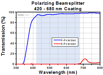
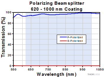
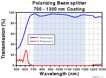


 Zoom
Zoom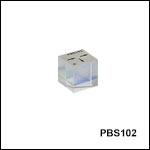


 Unmounted Beamsplitter Cubes