 Products Home / Motorized Stages / Long Travel Linear Motorized Stages (>100 mm) / 100 mm Linear Translation Stage, Direct-Drive Brushless Servo Motor
100 mm Linear Translation Stage, Direct-Drive Brushless Servo Motor
- 100 mm Travel at Speeds up to 500 mm/s
- Brushless DC Servo Motors
- Stackable in XY Configuration
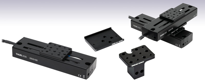
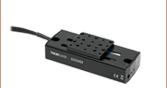
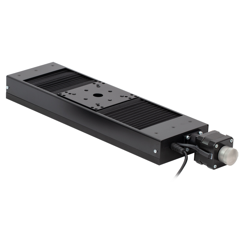
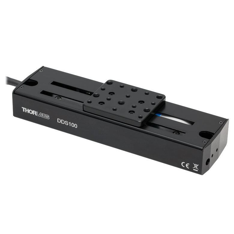
DDS100
100 mm (3.9") Servo Motor
Translation Stage
DDSMA2
End Mounting Adapter
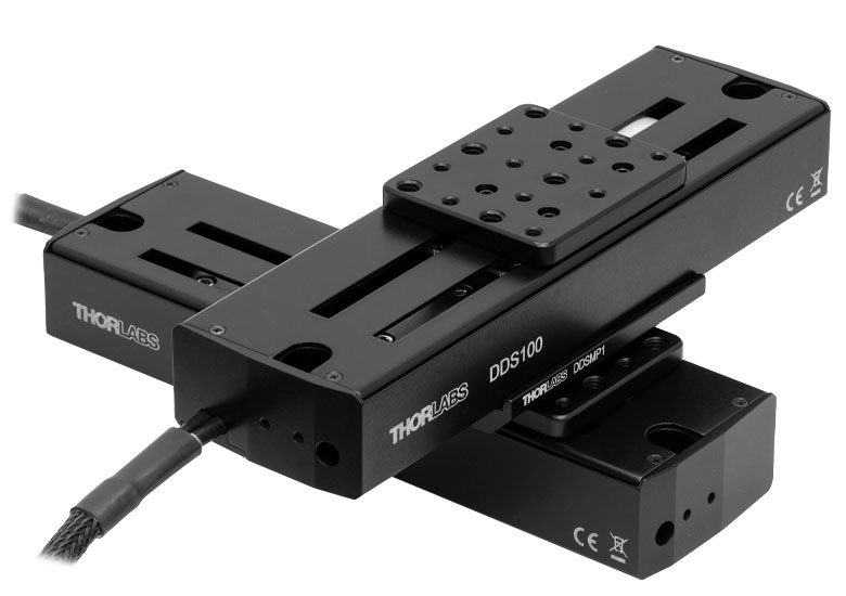
Application Idea
Two DDS100 Stages in
XY Configuration,
Using an DDSMP1 Adapter Plate
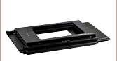
DDSMP1
XY Adapter Plate


Please Wait
| Item # | DDS100(/M) |
|---|---|
| Travel Range | 100 mm (3.9") |
| Speed (Max)a | 500 mm/s |
| Acceleration (Max) | 5000 mm/s2 |
| Bidirectional Repeatabilityb | ±1.5 µm |
| Straightness/Flatness | ±5.0 µm |
| Horizontal Load Capacity (Max) | 0.9 kg (1.98 lbs) |
| Min Incremental Movementc | 5.0 µm |
| Absolute On-Axis Accuracy | ±6.5 µm |
| Actuator Type | Brushless DC Servo Motor |
| Dimensions (L x W x H) | 195.0 mm x 57.0 mm x 35.0 mm (7.68" x 2.24" x 1.38") |
Features
- 100 mm Travel Range
- Integrated, Brushless DC Linear Servo Motor Actuators
- Linear Optical Encoders
- High-Quality, Precision-Engineered Linear Bearings
- 0.9 kg Horizontal Load Capacity
- Stackable in XY Configuration
Thorlabs' DDS100(/M) low-profile, direct-drive stage provides 100 mm of travel with ±6.5 µm on-axis accuracy and a maximum speed of 500 mm/s. The stage is ideal for applications that require high speeds and high positioning accuracy, including automated alignment, surface inspection, mapping, and probing.
An innovative, low-profile design with integrated, brushless linear motors eliminates the external housings that create mechanical clash points and impede access to the moving platform. The brushless DC servo motor removes the need for a lead screw, eliminating backlash, and internal flexible ducting ensures cables cannot become trapped as the mechanism moves. A precision-grooved linear bearing provides superior rigidity and linearity with excellent on-axis accuracy. This backlash-free operation coupled with high-resolution, closed-loop optical feedback ensures a minimal bidirectional repeatability of ±1.5 μm.
Click to Enlarge
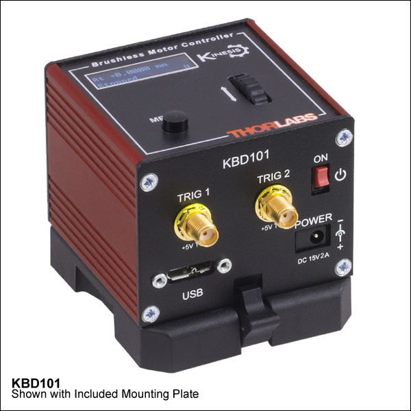
The KBD101 K-Cube Brushless DC Servo Motor Controller (sold separately below) is required to drive these stages.
| Motorized Linear Translation Stages | |
|---|---|
| 100 mm | Stepper |
| DC Servo | |
| 150 mm | Stepper |
| Stepper with Integrated Controller | |
| 220 mm | DC Servo |
| 300 mm | Stepper with Integrated Controller |
| DC Servo with Benchtop Controller | |
| 600 mm | DC Servo with Benchtop Controller |
| Optical Delay Line Kits | |
| Other Translation Stages | |
Controller
The required controller for the DDS100(/M) direct-drive, linear translation stage is the KBD101 K-Cube™ Brushless DC Motor Controller. This controller provides a user-configurable, S-curve acceleration/deceleration profile that enables fast, smooth positioning without vibration or shock. See below for a brief overview, or see the full web presentation for these Brushless DC Motor Controllers.
Mounting Adapters
For dual-axis applications, two stages can be bolted together in an XY configuration by using the DDSMP1 XY adapter plate as shown above. Note that these stages are not suitable for operation in a vertical (Z-axis) orientation. Please contact Tech Support for more details.
Adapter brackets are also available that allow optomechanical components to be mounted close to the linear travel of the stage in applications such as a delay line. Please see below for more details.
Please Note: Magnetic components should not be mounted to the stage platform. Magnets prevent proper homing and can affect the accuracy of the stage's encoder even after the magnetic component has been removed. When no power is applied, the platform of the stage has very little inertia and is virtually free running. This may make the stage unsuitable for applications where the stage's platform needs to remain in a set position when power is off.
| Item # | DDS100(/M) |
|---|---|
| Travel Range | 100 mm (3.9") |
| Speed (Max)a | 500 mm/s |
| Speed (Min)b | 70 nm/s |
| Acceleration (Max) | 5000 mm/s2 |
| Acceleration (Max) at 0.9 kg Load | 500 mm/s2 |
| Resolution | 500 nm |
| Bidirectional Repeatabilityc | ±1.5 µm |
| Backlash | N/A (No Leadscrew) |
| Min Incremental Movementd | 5.0 µm |
| Horizontal Load Capacity (Max) | 0.9 kg (1.98 lbs) |
| Absolute On-Axis Accuracy | ±6.5 µm |
| Straightness/Flatness | ±5.0 µm |
| Pitch | ±175 µrad |
| Yaw | ±175 µrad |
| Continuous Motor Forcee | 0.8 N |
| Peak Motor Force (5 s)f | 2.0 N |
| Bearing Type | High Rigidity Recirculating Precision Linear Bearing |
| Limit Switches | Magnetic Sensor at Each End of Stage |
| Operating Temperature Range | 5 to 40 °C (41 to 104 °F) |
| Motor Type | Brushless DC Linear Motor |
| Cable Length | 1 m (3.3') |
| Dimensions (L x W x H) | 195.0 mm x 57.0 mm x 35.0 mm (7.68" x 2.24" x 1.38") |
| Weight (with Cables) | 0.72 kg (1.6 lbs) |
Motor Control Connector
D-Type Male
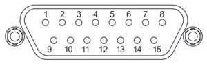
| Pin | Description | Pin | Description |
|---|---|---|---|
| 1 | Quadrature A- | 9 | Ground |
| 2 | Quadrature A+ | 10 | Motor Phase C |
| 3 | Quadrature B+ | 11 | Motor Phase A |
| 4 | Quadrature B- | 12 | Motor Phase B |
| 5 | Encoder Index I- | 13 | +5 V |
| 6 | Encoder Index I+ | 14 | Ground |
| 7 | Negative Limit | 15 | Stage ID |
| 8 | Positive Limit |
Thorlabs offers two platforms to drive our wide range of motion controllers: our Kinesis® software package or the legacy APT™ (Advanced Positioning Technology) software package. Either package can be used to control devices in the Kinesis family, which covers a wide range of motion controllers ranging from small, low-powered, single-channel drivers (such as the K-Cubes™ and T-Cubes™) to high-power, multi-channel, modular 19" rack nanopositioning systems (the APT Rack System).
The Kinesis Software features .NET controls which can be used by 3rd party developers working in the latest C#, Visual Basic, LabVIEW™, or any .NET compatible languages to create custom applications. Low-level DLL libraries are included for applications not expected to use the .NET framework. A Central Sequence Manager supports integration and synchronization of all Thorlabs motion control hardware.

Kinesis GUI Screen
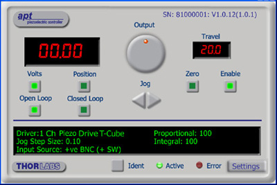
APT GUI Screen
Our legacy APT System Software platform offers ActiveX-based controls which can be used by 3rd party developers working on C#, Visual Basic, LabVIEW™, or any Active-X compatible languages to create custom applications and includes a simulator mode to assist in developing custom applications without requiring hardware.
By providing these common software platforms, Thorlabs has ensured that users can easily mix and match any of the Kinesis and APT controllers in a single application, while only having to learn a single set of software tools. In this way, it is perfectly feasible to combine any of the controllers from single-axis to multi-axis systems and control all from a single, PC-based unified software interface.
The software packages allow two methods of usage: graphical user interface (GUI) utilities for direct interaction with and control of the controllers 'out of the box', and a set of programming interfaces that allow custom-integrated positioning and alignment solutions to be easily programmed in the development language of choice.
A range of video tutorials is available to help explain our APT system software. These tutorials provide an overview of the software and the APT Config utility. Additionally, a tutorial video is available to explain how to select simulator mode within the software, which allows the user to experiment with the software without a controller connected. Please select the APT Tutorials tab above to view these videos.
Software
Kinesis Version 1.14.47
The Kinesis Software Package, which includes a GUI for control of Thorlabs' Kinesis and APT™ system controllers.
Also Available:
- Communications Protocol
Software
APT Version 3.21.6
The APT Software Package, which includes a GUI for control of Thorlabs' APT™ and Kinesis system controllers.
Also Available:
- Communications Protocol
The APT video tutorials available here fall into two main groups - one group covers using the supplied APT utilities and the second group covers programming the APT System using a selection of different programming environments.
Disclaimer: The videos below were originally produced in Adobe Flash. Following the discontinuation of Flash after 2020, these tutorials were re-recorded for future use. The Flash Player controls still appear in the bottom of each video, but they are not functional.
Every APT controller is supplied with the utilities APTUser and APTConfig. APTUser provides a quick and easy way of interacting with the APT control hardware using intuitive graphical control panels. APTConfig is an 'off-line' utility that allows various system wide settings to be made such as pre-selecting mechanical stage types and associating them with specific motion controllers.
APT User Utility
The first video below gives an overview of using the APTUser Utility. The OptoDriver single channel controller products can be operated via their front panel controls in the absence of a control PC. The stored settings relating to the operation of these front panel controls can be changed using the APTUser utility. The second video illustrates this process.
APT Config Utility
There are various APT system-wide settings that can be made using the APT Config utility, including setting up a simulated hardware configuration and associating mechanical stages with specific motor drive channels. The first video presents a brief overview of the APT Config application. More details on creating a simulated hardware configuration and making stage associations are present in the next two videos.
APT Programming
The APT Software System is implemented as a collection of ActiveX Controls. ActiveX Controls are language-independant software modules that provide both a graphical user interface and a programming interface. There is an ActiveX Control type for each type of hardware unit, e.g. a Motor ActiveX Control covers operation with any type of APT motor controller (DC or stepper). Many Windows software development environments and languages directly support ActiveX Controls, and, once such a Control is embedded into a custom application, all of the functionality it contains is immediately available to the application for automated operation. The videos below illustrate the basics of using the APT ActiveX Controls with LabVIEW, Visual Basic, and Visual C++. Note that many other languages support ActiveX including LabWindows CVI, C++ Builder, VB.NET, C#.NET, Office VBA, Matlab, HPVEE etc. Although these environments are not covered specifically by the tutorial videos, many of the ideas shown will still be relevant to using these other languages.
Visual Basic
Part 1 illustrates how to get an APT ActiveX Control running within Visual Basic, and Part 2 goes on to show how to program a custom positioning sequence.
LabVIEW
Full Active support is provided by LabVIEW and the series of tutorial videos below illustrate the basic building blocks in creating a custom APT motion control sequence. We start by showing how to call up the Thorlabs-supplied online help during software development. Part 2 illustrates how to create an APT ActiveX Control. ActiveX Controls provide both Methods (i.e. Functions) and Properties (i.e. Value Settings). Parts 3 and 4 show how to create and wire up both the methods and properties exposed by an ActiveX Control. Finally, in Part 5, we pull everything together and show a completed LabVIEW example program that demonstrates a custom move sequence.
Part 1: Accessing Online Help
Part 2: Creating an ActiveX Control
Part 3: Create an ActiveX Method
Part 4: Create an ActiveX Property
Part 5: How to Start an ActiveX Control
The following tutorial videos illustrate alternative ways of creating Method and Property nodes:
Create an ActiveX Method (Alternative)
Create an ActiveX Property (Alternative)
Visual C++
Part 1 illustrates how to get an APT ActiveX Control running within Visual C++, and Part 2 goes on to show how to program a custom positioning sequence.
MATLAB
For assistance when using MATLAB and ActiveX controls with the Thorlabs APT positioners, click here.
To further assist programmers, a guide to programming the APT software in LabVIEW is also available here.
| Posted Comments: | |
Leon Su
(posted 2023-10-26 22:10:06.487) Hello!
I have the KBD101 and DDSM100.
I am trying to program C code to control them on a PC. I want to know how to convert the device units to real-world units.
Thanks. do'neill
(posted 2023-10-31 05:43:18.0) Response from Daniel at Thorlabs. There are two ways to do this, you could convert from device units to real world units in your code rather than in the DLL. All the conversions for our communications protocol starting on page 39. For the DDSM100(/M) you will divide the position in device units by 2000 to get the position in real world units. As another way you could use the DLL, in this case you would use the command BMC_GetRealValueFromDeviceUnit() for the KBD101. Damiano Verardo
(posted 2023-09-14 14:03:16.947) Hello,
we are looking forward using the DDS100/M, but the 1 m cable is too short for our application. Are extensions available? Which requirements (e.g. shielding) are needed to buy/assemble one?
Thank you. do'neill
(posted 2023-09-15 07:47:13.0) Response from Daniel at Thorlabs. We do not have a stock cable that will allow you to do this but I will reach out to you to discuss your application with you BRIAN TEY
(posted 2021-12-24 00:55:51.08) Hi, I faced a problem with the DDSM100/M. When I tried to home it using the APT software, I received an error. The details are as follow:
Internal code: 18310705
Description: Hardware Notification/Response
Notes: A notification or response message has been received from a hardware unit. This may be indicative of a hardware fault or illegal command/parameter sent to the hardware.
Extra info: Hardware response code 34002 received from hardware unit SN 67863119 (in response to message ident 0). Response details:- HomingFailed
Any suggestion to fix this issue?
Thank you DJayasuriya
(posted 2022-01-04 09:22:23.0) Thank you for your inquiry. We will get in touch with you directly to trouble shoot your issue. ERIC AGOSTINI
(posted 2021-06-30 04:29:21.33) How many years can THORLABS commit to delivering the DDS100 / M? DJayasuriya
(posted 2021-07-01 05:15:49.0) Thank you for your inquiry. General rule would say 5 years minimum, but typically most of our items has a long life 10+ years. We will get in touch with you directly for any application questions that you might have. David Russell
(posted 2019-11-10 11:17:05.037) M3 tapped holes for end bracket mounting - Dwg shows 12.00 dim mtg surface to holes. Cad model shows 11.75 dim. cwright
(posted 2019-11-21 08:44:07.0) Response from Charles at Thorlabs: Hello David and thank you for contacting us. The DDSM stages contain feet of 0.25 mm height which have been machined into the base plates. This can be seen in the Auto CAD PDF drawing but is not explicitly called out in the dimensions. I believe if you measure the CAD model to the bottom of these feet you will find the measurements are in agreement with the drawing. Aaron Weber
(posted 2019-10-28 09:21:19.413) What is the encoder resolution for this stage? rmiron
(posted 2019-10-28 01:05:48.0) Response from Radu at Thorlabs: Hello Aaron. The encoder resolution for this stage is 500 nm. That information can be found online on page 35 of Kinesis' serial communications protocol's documentation. Len Ness
(posted 2019-04-24 18:08:13.493) The spec's state Horizontal Load Capacity (Max) 1.98lbs. Also the weight of the stage is 1.6lbs. So in an X/Y configuration does this mean you are limited to .38lbs load on the top stage? rmiron
(posted 2019-04-25 04:04:15.0) Response from Radu at Thorlabs: Hello, Len. You are correct. In an XY configuration, the load capacity is only 0.38 lbs. Brushless motor stages are great for applications which require high velocities, but they are not capable of handling very high loads. victor,lorenz
(posted 2017-10-25 21:19:56.627) I already have a DDSM100/M, but still unused. Now, I am willing to use it, but I did not buy the controller KBD101 at that time.
When I bought the DDSM100/M I thought the controller was the same as the controller for PRM1/MZ8, the KDC101, but now I noticed that they have different code number, although the tecnical description seems to be the same.
My question is, are the KBD101 and KDC101 controllers really different? I have the KDC101 and I wonder if I could use it to drive and control the DDSM100/M linear stage. Will it work properly? might I damage the linear stage or the controller?
Thanks,
Victor Lorenz bwood
(posted 2017-10-30 05:20:34.0) Response from Ben at Thorlabs: Thank you for your question. Unfortunately, the brushed DC servo motors controlled by the KBD101 and the direct drive motors controlled the KBD101 are fundamentally different, and as such the controlers are equally different. For example, the KDC101 has a peak current output of ~250 mA, while the KBD101 outputs the 2A needed by direct drive stages. As such, there is no way to adapt a KDC101 to run a DDSM100/M. ac2021
(posted 2016-08-30 07:33:54.227) We bought the DDSM/100M stage with K-Cube controller KBD101 and none of these appear in the APT software or Kinesis software. Could you help me troubleshooting this as it seems I'm not the only person in this situation? Cheers bhallewell
(posted 2016-08-31 05:29:42.0) Response from Ben at Thorlabs: Hi Alexandre, thank you for getting in touch with us. I will contact you to troubleshoot this with you. martin.kozak
(posted 2016-08-25 15:05:53.43) We bought the stage DDSM100/M with the KBD101 K-Cube driver. The APT software does not work. In the configuration utility it is not possible to choose our stage because it does not offer any motor to choose. It displays an internal error 13520709, MG17core.dll. Also the user interface of APT does not detect any device. Kinesis software works. In future we would like to control the stage via Matlab software. Can you also send me the initialization, home and absolute move dlls with a sample code? Thanks bwood
(posted 2016-08-26 05:43:33.0) Response from Ben at Thorlabs: I am sorry to hear about your problems here. Your local technical support office will be contacting you directly to troubleshoot this issue. We do have a APT and Matlab guide available, and we will also be sending you this document. alfred
(posted 2016-08-17 10:19:16.487) Dear Sir:
I come from Chroma ATE Inc.
I have some question for this Controllor Type:DDSM100/M Compact 100 mm Travel Direct Drive Stage With KBD101 K-Cube Brushless DC Servo Driver.
Please provide
1.Initialization
2.Home
3.Absolute Move
function
Dll and Sample Code to me msoulby
(posted 2016-08-18 07:49:14.0) Response from Mike at Thorlabs: We will contact you directly with more information about our motion control software package. alfred
(posted 2016-08-17 10:02:55.063) Control Type:DDSM100/M Compact 100 mm Travel Direct Drive Stage With KBD101 K-Cube Brushless DC Servo Driver
Please provide
1.Init
2.Home
3.Absolute Move
function Sample Code to me joshua.hendrickson.4
(posted 2016-07-06 10:35:11.03) Can the DDSM100 be controlled with the BBD201? bhallewell
(posted 2016-07-07 11:27:29.0) Response from Ben at Thorlabs: The DDSM100 cannot be driven by the BBD201 due to the cabling format not matching between these two devices. The output current of the BBD201 far exceeds the maximum limits for the DDSM100 motor. delphine.descloux
(posted 2015-12-10 17:18:08.82) Hi,
I have a question about TBD001 brushless servo controller and DDSM100 translation stage used together. The default PID settings are not working (the stage is not loaded yet, I plan to use it with less than 250g on it) and I was wondering if there are tables of appropriate settings ?
Thank you in advance. bhallewell
(posted 2015-12-14 03:43:48.0) Response from Ben at Thorlabs: Thank you for your question here. Please see page.14 of the DDSM100 manual. Here we list Recommended Position Loop PID Parameters & instruction for how these can be optimised based on observable characteristics of motion.
http://www.thorlabs.de/thorcat/23100/DDSM100-Manual.pdf
Further reference to Position & Current Loop parameters can be found on pg. 48-52 in the TBD001 manual.
https://www.thorlabs.com/thorcat/23100/TBD001-Manual.pdf vnalla
(posted 2015-11-23 17:20:56.11) My Dc stage is not working (can not connect to the TBD001)after installation of Windows 10, where as piezo stage still can work. besembeson
(posted 2015-12-03 03:18:52.0) Response from Bweh at Thorlabs USA: Our UK division has been in contact with you to resolve. tholste
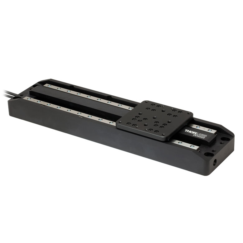
(posted 2012-07-26 14:49:00.0) A response from Tor at Thorlabs to rbjaculbia: Thank you for your interest in our Direct Drive Stages! For THz-TDS spectroscopy applications, we recommend our Delay Line Kit (http://www.thorlabs.com/NewGroupPage9.cfm?ObjectGroup_ID=5521). The DDS220 used in this kit offers repeatable delay shifts of 0.67 fs; the theoretical sensitivity would be 3.3 fs, given the resolution of the DDSM100. Please contact techsupport@thorlabs.com if you would like more details. rbjaculbia
(posted 2012-07-23 04:12:48.0) Hi,
We are looking to use this as a delay line for THz-TDS spectroscopy. Will this be viable? Thank you. |
Motorized Linear Translation Stages
Thorlabs' motorized linear translation stages are offered in a range of maximum travel distances, from a stage with 20 µm of piezo translation to our 600 mm direct drive stage. Many of these stages can be assembled in multi-axis configurations, providing XY or XYZ translation. For fiber coupling applications, please see our multi-axis stages, which offer finer adjustment than our standard motorized translation stages. In addition to motorized linear translation stages, we offer motorized rotation stages and goniometers. We also offer manual translation stages.
Piezo Stages
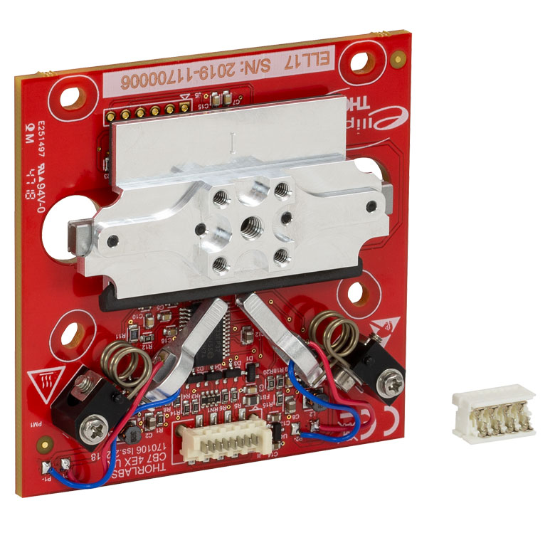
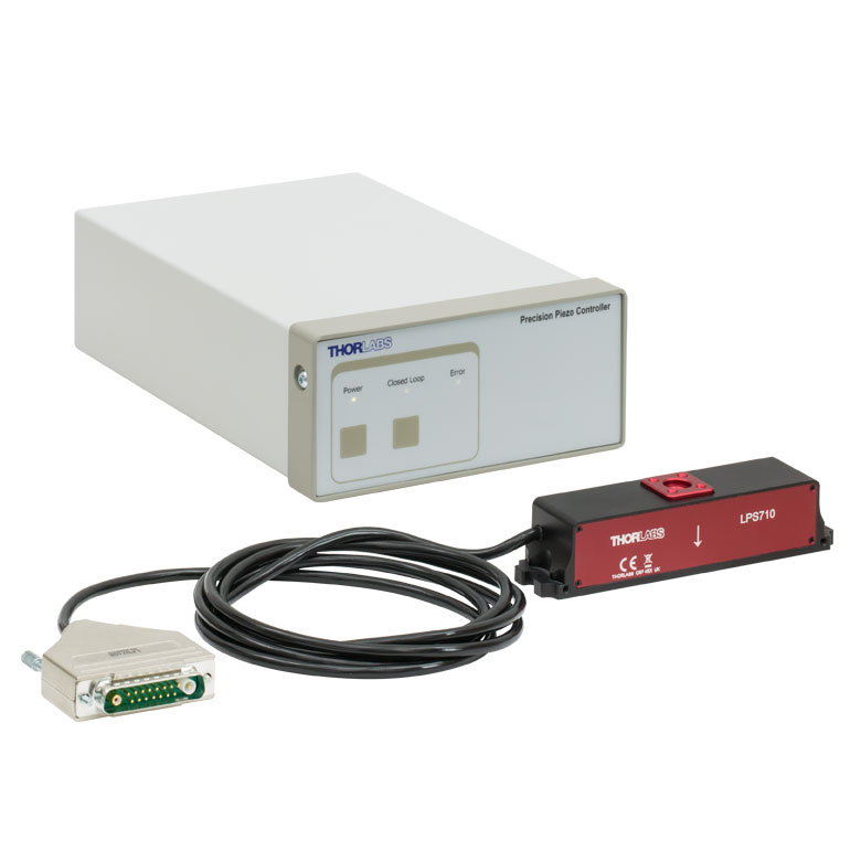
These stages incorporate piezoelectric elements in a variety of drive mechanisms. ORIC® stages incorporate piezo inertia drives that use "stick-slip" friction properties to obtain extended travel ranges. Our Nanoflex™ translation stages use standard piezo chips along with manual actuators. Elliptec® stages use resonant piezo motors to push and pull the moving platform through resonant elliptical motion. Our LPS710E z-axis stage features a mechanically amplified piezo design and includes a matched controller.
| Piezoelectric Stages | ||||
|---|---|---|---|---|
| Product Family | ORIC® PDXZ1 Closed-Loop 4.5 mm Vertical Stage |
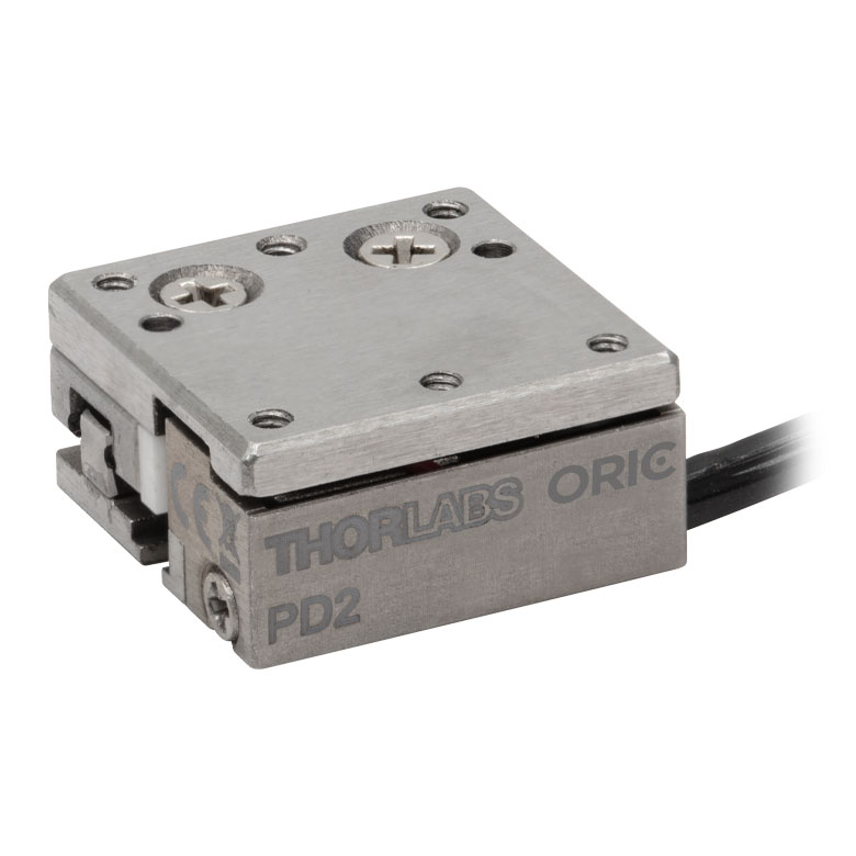
ORIC® PD2 Open-Loop 5 mm Stage |
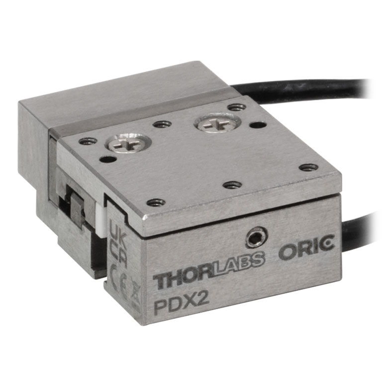
ORIC® PDX2 Closed-Loop 5 mm Stage |
|
| Click Photo to Enlarge |
 |
 |
 |
|
| Travel | 4.5 mm | 5 mm | ||
| Speed | 1 mm/s (Typ.)a | 10 mm/s (Typ. Max)b | 8 mm/s (Typ.)c | |
| Drive Type | Piezoelectric Inertia Drive | |||
| Possible Axis Configurations | Z | X, XY, XYZ | ||
| Mounting Surface Size |
45.0 mm x 42.0 mm | 13 mm x 13 mm | ||
| Additional Details | ||||
| Piezoelectric Stages | |||||
|---|---|---|---|---|---|
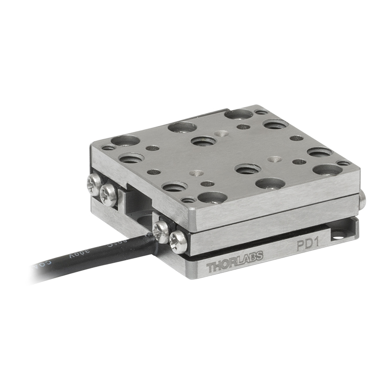
| Product Family | ORIC® PD1 Open-Loop 20 mm Stage |
ORIC® PD1D Open-Loop 20 mm Monolithic XY Stage |
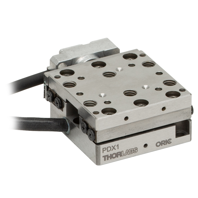
ORIC® PDX1 Closed-Loop 20 mm Stage |
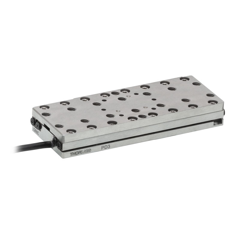
ORIC® PD3 Open-Loop 50 mm Stage |
|
| Click Photo to Enlarge |
 |
 |
 |
 |
|
| Travel | 20 mm | 50 mm | |||
| Speed | 3 mm/s (Typ. Max)a | 20 mm/s (Typ. Max)b | 10 mm/sc | ||
| Drive Type | Piezoelectric Inertia Drive | ||||
| Possible Axis Configurations | X, XY, XYZ | XY, XYZ | X, XY, XYZ | X, XY, XYZ | |
| Mounting Surface Size |
30 mm x 30 mm | 80 mm x 30 mm | |||
| Additional Details | |||||
| Piezoelectric Stages | ||||||
|---|---|---|---|---|---|---|
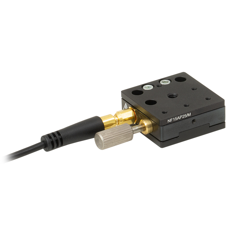
| Product Family | Nanoflex™ 20 µm Stage with 5 mm Actuator |
Nanoflex™ 25 µm Stage with 1.5 mm Actuator |
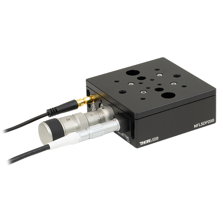
Elliptec® 28 mm Stage | Elliptec® 60 mm Stage | LPS710E 1.1 mm Vertical Stage | |
| Click Photo to Enlarge |
 |
 |
 |
 |
 |
|
| Travel | 20 µm + 5 mm Manual | 25 µm + 1.5 mm Manual | 28 mm | 60.0 mm | 1.1 mm | |
| Maximum Velocity | - | 180 mm/s | 90 mm/s | - | ||
| Drive Type | Piezo with Manual Actuator | Resonant Piezoelectric Motor | Amplified Piezo | |||
| Possible Axis Configurations | X, XY, XYZ | X | Z | |||
| Mounting Surface Size | 75 mm x 75 mm | 30 mm x 30 mm | 15 mm x 15 mm | 21 mm x 21 mm | ||
| Additional Details | ||||||
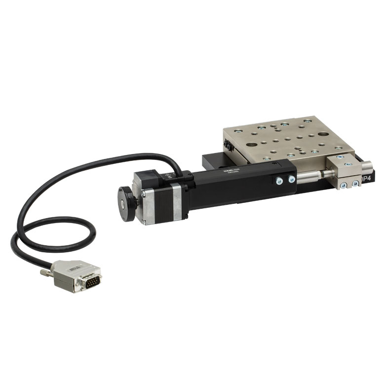
Stepper Motor Stages
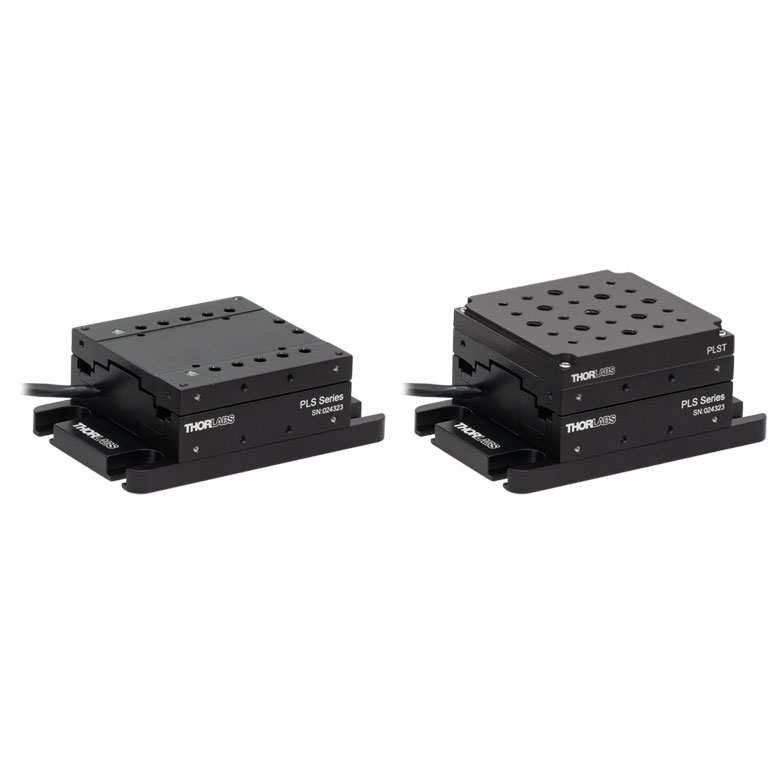
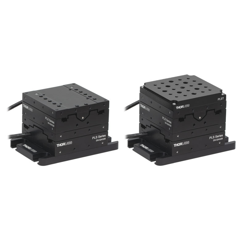
These translation stages feature removable or integrated stepper motors and long travel ranges up to 300 mm. Many of these stages either have integrated multi-axis capability (PLSXY) or can be assembled into multi-axis configurations (PLSX, LNR Series, NRT Series, and LTS Series stages). The MLJ150 stage also offers high load capacity vertical translation.
| Stepper Motor Stages | |||||
|---|---|---|---|---|---|
| Product Family | PLSX with and without PLST(/M) Top Plate 1" Stage |
PLSXY with and without PLST(/M) Top Plate 1" Stage |
LNR Series 25 mm Stage |
LNR Series 50 mm Stage |
|
| Click Photo to Enlarge |
 |
 |
 |
 |
|
| Travel | 1" | 25 mm | 50 mm | ||
| Maximum Velocity | 7.0 mm/s | 2.0 mm/s | 50 mm/s | ||
| Possible Axis Configurations |
X, XY | X, XY, XYZ | X, XY, XYZ | ||
| Mounting Surface Size |
3" x 3" | 60 mm x 60 mm | 100 mm x 100 mm | ||
| Additional Details | |||||
| Stepper Motor Stages | ||||||
|---|---|---|---|---|---|---|
| Product Family | NRT Series 100 mm Stage |
NRT Series 150 mm Stage |
LTS Series 150 mm Stage |
LTS Series 300 mm Stage |
MLJ250 50 mm Vertical Stage |
|
| Click Photo to Enlarge |
 |
 |
 |
 |
 |
|
| Travel | 100 mm | 150 mm | 150 mm | 300 mm | 50 mm | |
| Maximum Velocity | 30 mm/s | 50 mm/s | 3.0 mm/s | |||
| Possible Axis Configurations |
X, XY, XYZ | X, XY, XYZ | Z | |||
| Mounting Surface Size |
84 mm x 84 mm | 100 mm x 90 mm | 148 mm x 131 mm | |||
| Additional Details | ||||||
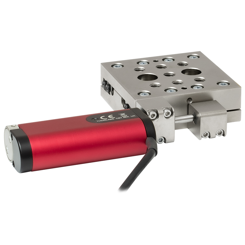
DC Servo Motor Stages
Thorlabs offers linear translation stages with removable or integrated DC servo motors. These stages feature low profiles and many can be assembled in multi-axis configurations.
| DC Servo Motor Stages | ||||
|---|---|---|---|---|
| Product Family | MT Series 12 mm Stages |
PT Series 25 mm Stages |
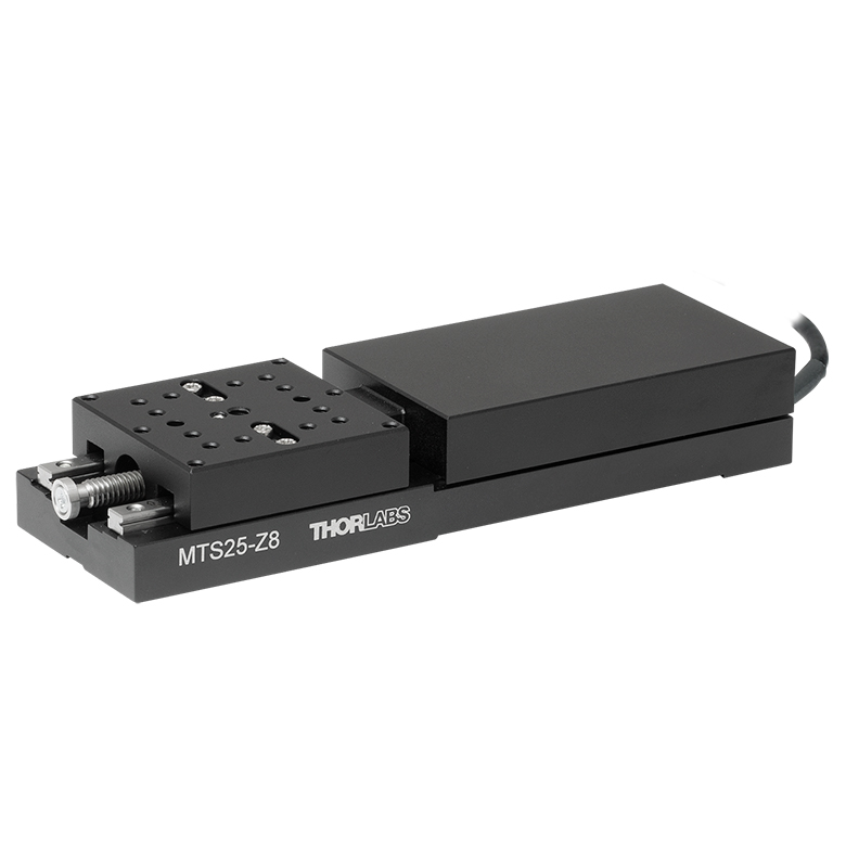
MTS Series 25 mm Stage |
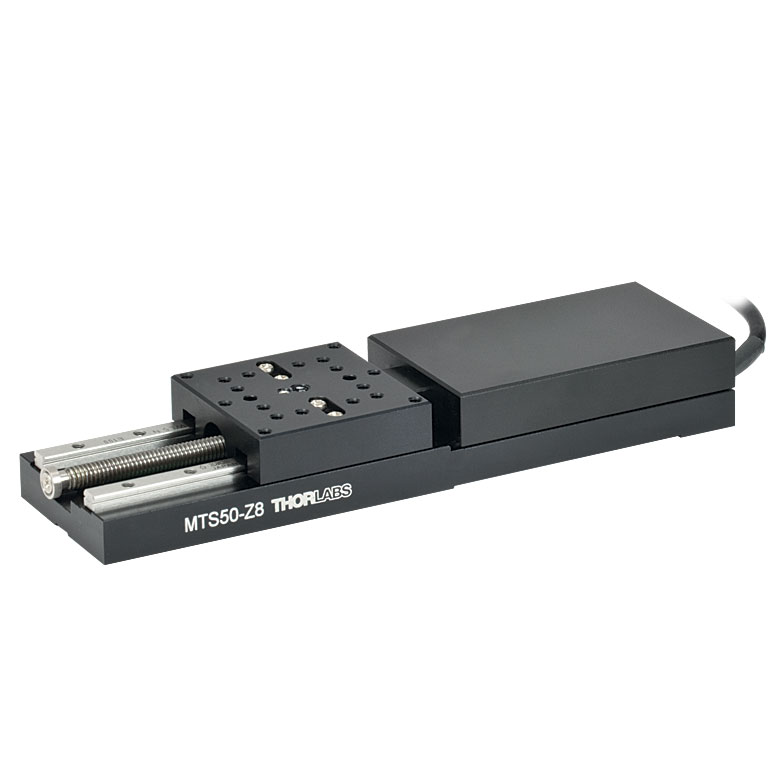
MTS Series 50 mm Stage |
| Click Photo to Enlarge |
 |
 |
 |
 |
| Travel | 12 mm | 25 mm | 25 mm | 50 mm |
| Maximum Velocity | 2.6 mm/s | 2.4 mm/s | ||
| Possible Axis Configurations | X, XY, XYZ | X, XY, XYZ | ||
| Mounting Surface Size |
61 mm x 61 mm | 101.6 mm x 76.2 mm | 43 mm x 43 mm | |
| Additional Details | ||||
| DC Servo Motor Stages | ||||
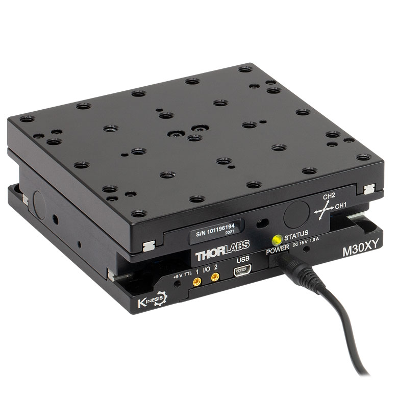
|---|---|---|---|---|
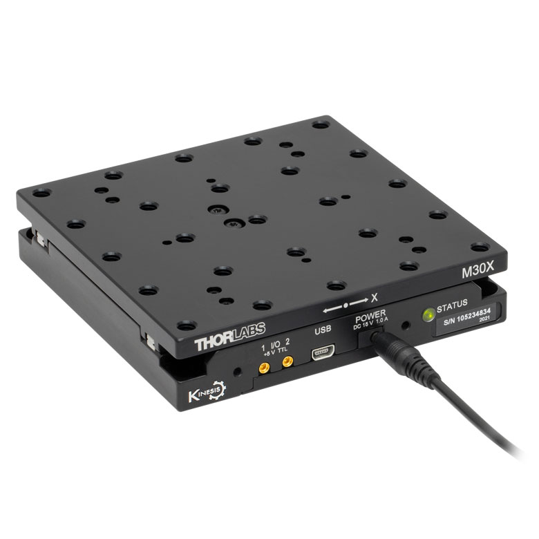
| Product Family | M30 Series 30 mm Stage |
M30 Series 30 mm Monolithic XY Stage |
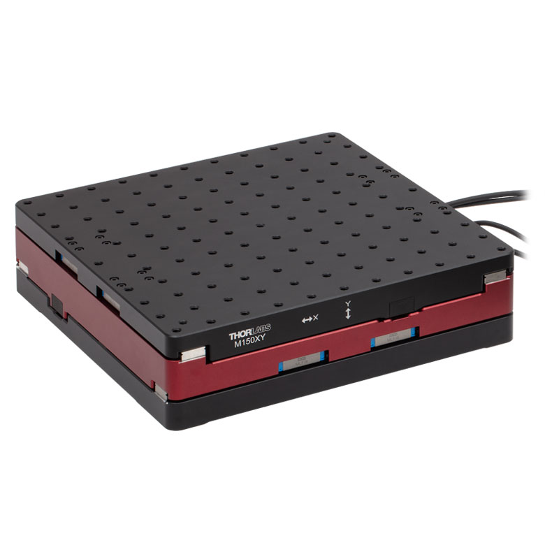
M150 Series 150 mm XY Stage |
KVS30 30 mm Vertical Stage |
| Click Photo to Enlarge |
 |
 |
 |
 |
| Travel | 30 mm | 150 mm | 30 mm | |
| Maximum Velocity | 2.4 mm/s | X-Axis: 170 mm/s Y-Axis: 230 mm/s |
8.0 mm/s | |
| Possible Axis Configurations | X, Z | XY, XZ | XY | Z |
| Mounting Surface Size |
115 mm x 115 mm | 272.4 mm x 272.4 mm | 116.2 mm x 116.2 mm | |
| Additional Details | ||||
Direct Drive Stages
These low-profile stages feature integrated brushless DC servo motors for high speed translation with zero backlash. When no power is applied, the platforms of these stages have very little inertia and are virtually free running. Hence these stages may not be suitable for applications where the stage's platform needs to remain in a set position when the power is off. We do not recommend mounting these stages vertically.
| Direct Drive Stages | |||||
|---|---|---|---|---|---|
| Product Family | DDS Series 50 mm Stage |
DDS Series 100 mm Stage |
DDS Series 220 mm Stage |
DDS Series 300 mm Stage |
DDS Series 600 mm Stage |
| Click Photo to Enlarge |
 |
 |
 |
 |
 |
| Travel | 50 mm | 100 mm | 220 mm | 300 mm | 600 mm |
| Maximum Velocity | 500 mm/s | 300 mm/s | 400 mm/s | 400 mm/s | |
| Possible Axis Configurations | X, XY | X, XY | X | X | |
| Mounting Surface Size | 60 mm x 52 mm | 88 mm x 88 mm | 120 mm x 120 mm | ||
| Additional Details | |||||

 Zoom
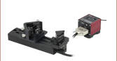
ZoomCharacterized by high-speed translation and high positional accuracy, the DDS100(/M) stage is well-suited for surface mapping and characterization applications where there is a need to move a camera or probe at constant velocity while simultaneously capturing data. Very precise, fine positioning and control is easily achieved through a combination of the stable closed-loop control system and a KBD101 controller.
Please Note: Magnetic components should not be mounted to the stage platform. Magnets prevent proper homing and can affect the accuracy of the stage's encoder even after the magnetic component has been removed. These stages are not suitable for operation in a vertical (Z-axis) orientation. When no power is applied, the platform of the stage has very little inertia and is virtually free running. This may make the stage unsuitable for applications where the stage's platform needs to remain in a set position when power is off.

 Zoom
Zoom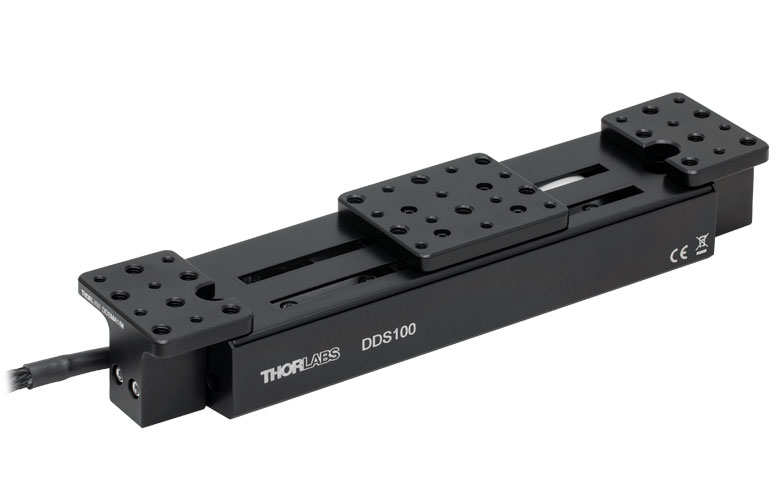
Click to Enlarge
Optomechanical components can be mounted next to the travel range of the DDS100 Stage using DDSMA1 and DDSMA2 Adapter Plates.
Click for Details
Two DDS100 stages can be connected in an XY configuration using the DDSMP1 XY Adapter Plate.
For 2-axis applications, two DDS100(/M) stages can be bolted together in an XY configuration using the DDSMP1(/M) adapter plate as shown in the photo to the right.
The DDSMA1(/M) and DDSMA2(/M) adapter plates attach to the end of the DDS100(/M) stage using the two supplied M3 x 20 screws (see image to the right) and allow optomechanical components to be mounted close to the linear travel of the stage in applications such as a delay line. The plates are drilled and tapped with six 1/4"-20 (M6 x 1.0) and five 8-32 (M4 x 0.7) holes.

 Zoom
Zoom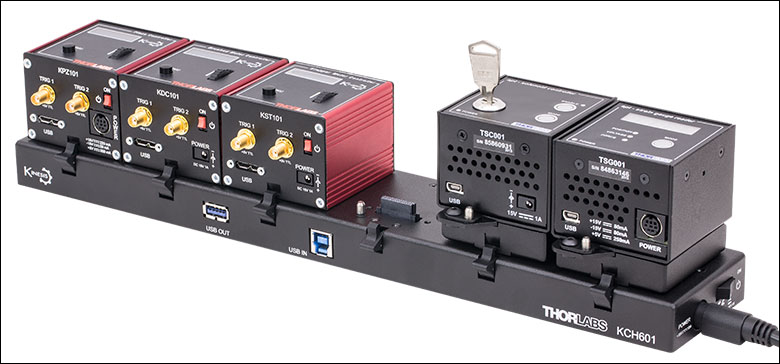
Click to Enlarge
KCH601 USB Controller Hub (Sold Separately) with Installed K-Cube and T-Cube™ Modules (T-Cubes shown on the KAP101 Adapter)
- Front Panel Velocity Wheel and Digital Display for Controlling Motorized Stages or Actuators
- Two Bidirectional SMC Trigger Ports to Read or Control External Equipment
- Interfaces with Computer Using Included USB Cable
- Fully Compatible with Kinesis® or APT™ Software Packages
- Compact Footprint: 60.0 mm x 60.0 mm x 49.2 mm (2.42" x 2.42" x 1.94")
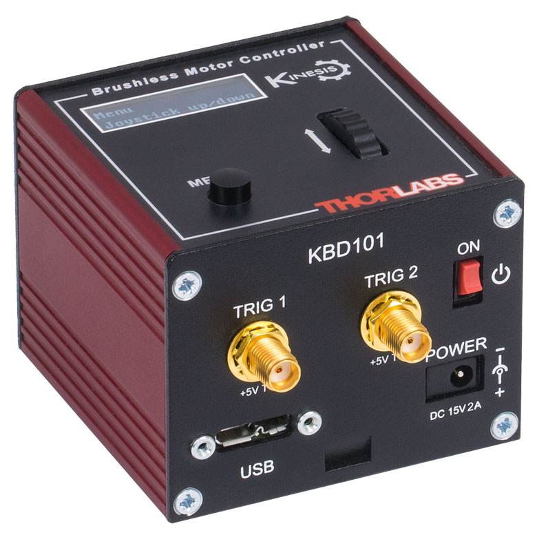
- Power Supply Not Included (See Below)
Thorlabs' KBD101 K-Cube™ Brushless DC Motor Controller provides local and computerized control of a single motor axis. It features a top-mounted control panel with a velocity wheel that supports four-speed bidirectional control with forward and reverse jogging as well as position presets. A backlit digital display is also included that can have the backlit dimmed or turned off using the the top-panel menu options. The front of the unit contains two bidirectional SMC trigger ports that can be used to read a 5 V external logic signal or output a 5 V logic signal to control external equipment. Each port can be independently configured.
The unit is fully compatible with our new Kinesis software package and our legacy APT control software.
Please note that this controller does not ship with a power supply. Compatible power supplies are listed below. Additional information can be found on the main KBD101 Brushless DC Servo Motor Controller page.

 Zoom
Zoom
Click for Details
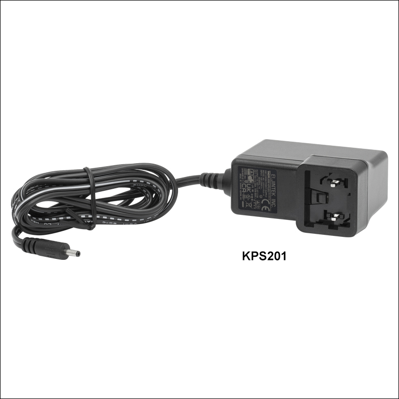
Each KPS201 power supply includes one region-specific adapter, which can be selected upon checkout.
Click to Enlarge
The KPS201 Power Supply Unit
- Individual Power Supply
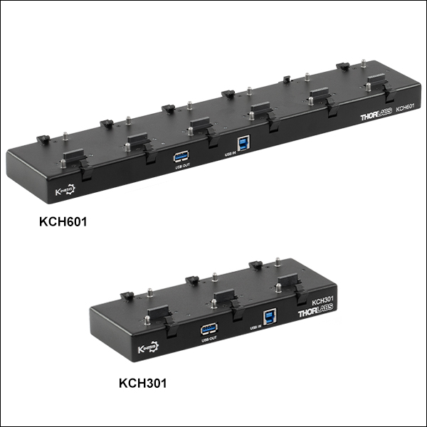
- KPS201: For K-Cubes™ or T-Cubes™ with 3.5 mm Jacks
- USB Controller Hubs Provide Power and Communications
- KCH301: For up to Three K-Cubes or T-Cubes
- KCH601: For up to Six K-Cubes or T-Cubes
The KPS201 power supply outputs +15 VDC at up to 2.66 A and can power a single K-Cube or T-Cube with a 3.5 mm jack. It plugs into a standard wall outlet.
The KCH301 and KCH601 USB Controller Hubs each consist of two parts: the hub, which can support up to three (KCH301) or six (KCH601) K-Cubes or T-Cubes, and a power supply that plugs into a standard wall outlet. The hub draws a maximum current of 10 A; please verify that the cubes being used do not require a total current of more than 10 A. In addition, the hub provides USB connectivity to any docked K-Cube or T-Cube through a single USB connection.
For more information on the USB Controller Hubs, see the full web presentation.