 Products Home / Optical Elements / Optical Lenses / Aspheric Lenses: Molded & Precision Polished / Molded Aspheric Lenses / Molded IR Aspheric Lenses
Molded IR Aspheric Lenses
- NAs from 0.18 to 0.85
- Diffraction-Limited Performance
- Broadband AR-Coated Optics
- Collimate or Focus Light with a Single Element
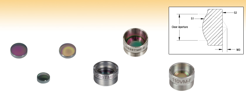
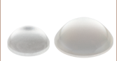
390028-D
Ø8.0 mm, f = 5.95 mm
AR Coating: 1.8 - 3 µm
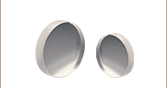
390036-E
Ø6.50 mm, f = 4.00 mm
AR Coating: 3 - 5 µm
390028-F
Ø8.0 mm, f = 5.95 mm
AR Coating: 8 - 12 µm
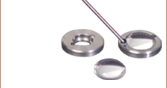
C036TME-D
M9 x 0.5 Thread, f = 4.00 mm
AR Coating: 1.8 - 3 µm
C028TME-E
M10 x 0.5 Thread, f = 5.95 mm
AR Coating: 3 - 5 µm
110VM-F
M8 x 0.5 Thread, f = 11.0 mm
AR Coating: 8 - 12 µm


Please Wait
| Aspheric Lens Selection Guide |
|---|
| Uncoated |
| 350 - 700 nm (-A Coating) |
| 600 - 1050 nm (-B Coating) |
| 1050 - 1700 nm (-C Coating) |
| 1.8 - 3 µm (-D Coating) |
| 3 - 5 µm (-E Coating) |
| 8 - 12 µm (-F Coating) |
| 405 nm V-Coating |
| 1064 nm V-Coating |
| Webpage Features | |
|---|---|
| |
Click for complete specifications. |
| Performance Hyperlink | Click to view item-specific focal length shift data and spot diagrams at various wavelengths. |
 Zemax Files` Zemax Files` |
|---|
| Click on the red Document icon next to the item numbers below to access the Zemax file download. Our entire Zemax Catalog is also available. |
| Common Specifications | ||
|---|---|---|
| Substrate | Black Diamond-2 | VIG06 |
| Refractive Indexa | 2.630 ± 0.003 at 2.5 µm | 2.795 ± 0.003 @ 3.5 µm |
| Damage Threshold (Typical) | 100 W/cm2 @ (1064 nm, CW)b 0.1 J/cm2 @ (1064 nm, 10 ns)b |
N/A |
| Surface Quality (Bulk Material) |
80-50 Scratch-Dig | |
| Coefficient of Thermal Expansion |
13.5 x 10⁻⁶ / °C | 20.8 x 10⁻⁶ / °C |
| Thermooptic Coefficient (Δn / ΔT) | 91 x 10-6 / °C | 32.1 x 10⁻⁶ / °C |
Features
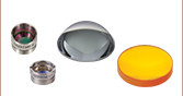
- Focus or Collimate Light Without Introducing Spherical Aberration
- Ø3.3 mm, Ø4.00 mm, Ø5.00 mm, or Ø7.60 mm Unmounted Clear Aperture
- AR Coated for 1.8 - 3 µm (-D), 3 - 5 µm (-E), or 8 - 12 µm (-F)
- Available Unmounted or Mounted in a Threaded, Engraved Stainless Steel Housing
- BD-2 and VIG06 Substrates Provide Stable Operation up to 130 °C and 110 °C Respectively
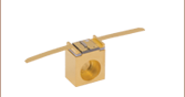
Spherical aberration often prevents a spherical lens from achieving diffraction-limited design. The surfaces of an aspheric lens are designed to minimize spherical aberration, thereby providing a robust single element solution for many applications, such as collimating the output of a fiber or laser diode, coupling light into a fiber, spatial filtering, or imaging light onto a detector. In particular, our IR aspheric lenses are ideal for collimating light from mid-wavelength infrared (MWIR) and long-wavelength infrared (LWIR) sources, including Quantum Cascade Lasers (QCLs).
All of the molded glass lenses featured on this page are available with an antireflection coating for either the 1.8 - 3 µm, 3 - 5 µm, or 8 - 12 µm range deposited on both sides. Other AR coating options are listed in the Aspheric Lens Selection Guide table at right.
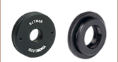
These molded glass lenses are available unmounted or premounted in stainless steel lens housings that are engraved with the part number for easy identification. These housings have a metric external threading that makes them easy to integrate into an optical setup or OEM application. For example, they are readily adapted to our SM1 (1.035"-40) Lens Tubes by using our Aspheric Lens Adapters. Mounted aspheres can also be used as a drop-in replacement for multi-element microscope objectives in conjunction with our RMS-threaded Objective Replacement Adapters.
If an unmounted aspheric lens is being used to collimate the light from a point source or laser diode, the side with the greater radius of curvature should face the point source or laser diode. To collimate light using one of our mounted aspheric lenses, orient the housing so that the externally threaded end of the mount faces the source.
Black Diamond
Black Diamond-2 (BD-2), a chalcogenide made of an amorphous mixture of germanium (28%), antimony (12%), and selenium (60%), has several advantages over germanium, which is traditionally used to fabricate IR optics. BD-2's thermally stable refractive index (see the Refractive Index tab) and low coefficient of thermal expansion (13.5 x 10⁻⁶ / °C) result in a smaller change in focal length as a function of temperature than for germanium. Additionally, germanium suffers from transmission loss as temperature increases, while BD-2 aspheric lenses can be used in environments up to 130 °C. This material performs particularly well over the 1.7 - 2.2 µm spectral range, providing >99% transmission and a flat dispersion curve. Click here to download a pdf of the SDS for BD-2.
VIG06
VIG06 is a chalcogenide made of an amorphous mixture of arsenic (40%) and selenium (60%). VIG06 has similar optical properties to BD-2, but with a slightly higher refractive index and coefficient of thermal expansion (20.8 x 10⁻⁶ / °C) and a lower thermooptic coefficient (32.1 x 10⁻⁶ / °C). VIG06 aspheric lenses can be used in environments with temperatures up to 110 °C. Click here to download a pdf of the SDS for VIG06.

The shaded region in each graph indicates the range for which the coating is specified. Please note that these curves are typical; slight variations in performance may occur from lot to lot.
| Herzberger Coefficient |
Value | |
|---|---|---|
| BD-2 | VIG06 | |
| A | 2.614 | 2.789 |
| B | 1.491 x 10⁻¹ | 1.120 x 10⁻¹ |
| C | -2.875 x 10⁻¹ | 1.782 x 10⁻² |
| D | -9.573 x 10⁻⁵ | -1.109 x 10⁻⁴ |
| E | -5.109 x 10⁻⁷ | -7.893 x 10⁻⁸ |
| F | 9.894 x 10⁻¹⁰ | -9.027 x 10⁻¹² |
The refractive indices of Black Diamond-2 (BD-2) and VIG06 as a function of wavelength, shown above, was calculated using the Herzberger Equation, an infrared-specific analog of the Sellmeier Equation. The Herzberger coefficients for BD-2 and VIG06 are given to the table to the right.
Herzberger Equation (for λ in µm)
Choosing a Lens for Fiber Coupling
Aspheric lenses are commonly used to couple incident light with a spot size of 1 - 5 mm into a single mode fiber. The following simple example illustrates the key specifications to consider when trying to choose the correct lens.
Example
- Wavelength: 1950 nm
- Fiber: P1-1950-FC-1
- Collimated Beam Diameter Prior to Lens: 1.2 mm
At 1950 nm, Thorlabs' P1-1950-FC-1 single mode patch cable is specified with a mode field diameter (MFD) of 8.0 μm. This specification should be matched to the diffraction-limited spot size given by the following equation:
Here, f is the focal length of the lens, λ is the wavelength of the input light, and D is the diameter of the collimated beam incident on the lens. Solving for the desired focal length of the collimating lens yields:
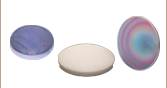
The mounted aspheric lens that is AR coated for our 1950 nm wavelength and most closely matches the desired focal length of 3.87 mm is our C093TME-D (f = 3.00 mm), shown below. Its clear aperture of 5.00 mm is easily larger than the collimated beam diameter of 1.2 mm. It therefore meets the requirements of the example setup.
For optimal coupling, the spot size of the focused beam should be smaller than the MFD of the single mode fiber. Therefore, if an aspheric lens is not available that provides an exact match, choose an aspheric lens with a focal length that is shorter than that yielded by the calculation above. Alternatively, assuming the clear aperture of the aspheric lens is sufficiently large, the beam can be expanded before the aspheric lens to allow the focused beam to have a tighter spot.
Click to Enlarge
Reference Drawing
Aspheric Lens Design Formula
| Definitions of Variables | |
|---|---|
| z | Sag (Surface Profile) as a Function of Y |
| Y | Radial Distance from Optical Axis |
| R | Radius of Curvature |
| k | Conic Constant |
| An | nth Order Aspheric Coefficient |
The aspheric surfaces of these lenses may be described using a polynomial expansion in Y, the radial distance from the optical axis. The surface profile or sagitta (often abbreviated as sag) is denoted by z, and is given by the following expression:
where R is the radius of curvature, k is the conic constant, and the An are the nth order aspheric coefficients. The sign of R is determined by whether the center of curvature for the lens surface is located to the right or left of the lens' vertex; a positive R indicates that the center of curvature is located to the right of the vertex, while a negative R indicates that the center of curvature is located to the left of the vertex. For example, the radius of curvature for the left surface of a biconvex lens would be specified as positive, while the radius of curvature for its right surface would be specified as negative.
Aspheric Lens Coefficients
Due to the rotational symmetry of the lens surface, only even powers of Y are contained in the polynomial expansion above. The target values of the aspheric coefficients for each product can be found by clicking either on the blue Info Icons in the tables below (![]() ) or on the red documents icon (
) or on the red documents icon ( ) next to each lens sold below.
| BD-2 Damage Threshold Specificationsa | |
|---|---|
| Damage Specification Type | Damage Threshold |
| Pulsed | 0.1 J/cm2 (1064 nm, 10 ns) |
| CW | 100 W/cm2 (1064 nm) |
Damage Threshold Data for Thorlabs' BD-2 Molded IR Aspheric Lenses
The specifications to the right are measured data for Thorlabs' molded IR aspheric lenses made of the Black Diamond-2 (BD-2) material. Damage threshold specifications are constant for all black diamond IR aspheric lenses, regardless of the focal point of the lens. These specifications are limited by the AR coating and are not guaranteed.
Laser Induced Damage Threshold Tutorial
The following is a general overview of how laser induced damage thresholds are measured and how the values may be utilized in determining the appropriateness of an optic for a given application. When choosing optics, it is important to understand the Laser Induced Damage Threshold (LIDT) of the optics being used. The LIDT for an optic greatly depends on the type of laser you are using. Continuous wave (CW) lasers typically cause damage from thermal effects (absorption either in the coating or in the substrate). Pulsed lasers, on the other hand, often strip electrons from the lattice structure of an optic before causing thermal damage. Note that the guideline presented here assumes room temperature operation and optics in new condition (i.e., within scratch-dig spec, surface free of contamination, etc.). Because dust or other particles on the surface of an optic can cause damage at lower thresholds, we recommend keeping surfaces clean and free of debris. For more information on cleaning optics, please see our Optics Cleaning tutorial.
Testing Method
Thorlabs' LIDT testing is done in compliance with ISO/DIS 11254 and ISO 21254 specifications.
First, a low-power/energy beam is directed to the optic under test. The optic is exposed in 10 locations to this laser beam for 30 seconds (CW) or for a number of pulses (pulse repetition frequency specified). After exposure, the optic is examined by a microscope (~100X magnification) for any visible damage. The number of locations that are damaged at a particular power/energy level is recorded. Next, the power/energy is either increased or decreased and the optic is exposed at 10 new locations. This process is repeated until damage is observed. The damage threshold is then assigned to be the highest power/energy that the optic can withstand without causing damage. A histogram such as that below represents the testing of one BB1-E02 mirror.

The photograph above is a protected aluminum-coated mirror after LIDT testing. In this particular test, it handled 0.43 J/cm2 (1064 nm, 10 ns pulse, 10 Hz, Ø1.000 mm) before damage.

| Example Test Data | |||
|---|---|---|---|
| Fluence | # of Tested Locations | Locations with Damage | Locations Without Damage |
| 1.50 J/cm2 | 10 | 0 | 10 |
| 1.75 J/cm2 | 10 | 0 | 10 |
| 2.00 J/cm2 | 10 | 0 | 10 |
| 2.25 J/cm2 | 10 | 1 | 9 |
| 3.00 J/cm2 | 10 | 1 | 9 |
| 5.00 J/cm2 | 10 | 9 | 1 |
According to the test, the damage threshold of the mirror was 2.00 J/cm2 (532 nm, 10 ns pulse, 10 Hz, Ø0.803 mm). Please keep in mind that these tests are performed on clean optics, as dirt and contamination can significantly lower the damage threshold of a component. While the test results are only representative of one coating run, Thorlabs specifies damage threshold values that account for coating variances.
Continuous Wave and Long-Pulse Lasers
When an optic is damaged by a continuous wave (CW) laser, it is usually due to the melting of the surface as a result of absorbing the laser's energy or damage to the optical coating (antireflection) [1]. Pulsed lasers with pulse lengths longer than 1 µs can be treated as CW lasers for LIDT discussions.
When pulse lengths are between 1 ns and 1 µs, laser-induced damage can occur either because of absorption or a dielectric breakdown (therefore, a user must check both CW and pulsed LIDT). Absorption is either due to an intrinsic property of the optic or due to surface irregularities; thus LIDT values are only valid for optics meeting or exceeding the surface quality specifications given by a manufacturer. While many optics can handle high power CW lasers, cemented (e.g., achromatic doublets) or highly absorptive (e.g., ND filters) optics tend to have lower CW damage thresholds. These lower thresholds are due to absorption or scattering in the cement or metal coating.

LIDT in linear power density vs. pulse length and spot size. For long pulses to CW, linear power density becomes a constant with spot size. This graph was obtained from [1].

Pulsed lasers with high pulse repetition frequencies (PRF) may behave similarly to CW beams. Unfortunately, this is highly dependent on factors such as absorption and thermal diffusivity, so there is no reliable method for determining when a high PRF laser will damage an optic due to thermal effects. For beams with a high PRF both the average and peak powers must be compared to the equivalent CW power. Additionally, for highly transparent materials, there is little to no drop in the LIDT with increasing PRF.
In order to use the specified CW damage threshold of an optic, it is necessary to know the following:
- Wavelength of your laser
- Beam diameter of your beam (1/e2)
- Approximate intensity profile of your beam (e.g., Gaussian)
- Linear power density of your beam (total power divided by 1/e2 beam diameter)
Thorlabs expresses LIDT for CW lasers as a linear power density measured in W/cm. In this regime, the LIDT given as a linear power density can be applied to any beam diameter; one does not need to compute an adjusted LIDT to adjust for changes in spot size, as demonstrated by the graph to the right. Average linear power density can be calculated using the equation below.

The calculation above assumes a uniform beam intensity profile. You must now consider hotspots in the beam or other non-uniform intensity profiles and roughly calculate a maximum power density. For reference, a Gaussian beam typically has a maximum power density that is twice that of the uniform beam (see lower right).
Now compare the maximum power density to that which is specified as the LIDT for the optic. If the optic was tested at a wavelength other than your operating wavelength, the damage threshold must be scaled appropriately. A good rule of thumb is that the damage threshold has a linear relationship with wavelength such that as you move to shorter wavelengths, the damage threshold decreases (i.e., a LIDT of 10 W/cm at 1310 nm scales to 5 W/cm at 655 nm):

While this rule of thumb provides a general trend, it is not a quantitative analysis of LIDT vs wavelength. In CW applications, for instance, damage scales more strongly with absorption in the coating and substrate, which does not necessarily scale well with wavelength. While the above procedure provides a good rule of thumb for LIDT values, please contact Tech Support if your wavelength is different from the specified LIDT wavelength. If your power density is less than the adjusted LIDT of the optic, then the optic should work for your application.
Please note that we have a buffer built in between the specified damage thresholds online and the tests which we have done, which accommodates variation between batches. Upon request, we can provide individual test information and a testing certificate. The damage analysis will be carried out on a similar optic (customer's optic will not be damaged). Testing may result in additional costs or lead times. Contact Tech Support for more information.
Pulsed Lasers
As previously stated, pulsed lasers typically induce a different type of damage to the optic than CW lasers. Pulsed lasers often do not heat the optic enough to damage it; instead, pulsed lasers produce strong electric fields capable of inducing dielectric breakdown in the material. Unfortunately, it can be very difficult to compare the LIDT specification of an optic to your laser. There are multiple regimes in which a pulsed laser can damage an optic and this is based on the laser's pulse length. The highlighted columns in the table below outline the relevant pulse lengths for our specified LIDT values.
Pulses shorter than 10-9 s cannot be compared to our specified LIDT values with much reliability. In this ultra-short-pulse regime various mechanics, such as multiphoton-avalanche ionization, take over as the predominate damage mechanism [2]. In contrast, pulses between 10-7 s and 10-4 s may cause damage to an optic either because of dielectric breakdown or thermal effects. This means that both CW and pulsed damage thresholds must be compared to the laser beam to determine whether the optic is suitable for your application.
| Pulse Duration | t < 10-9 s | 10-9 < t < 10-7 s | 10-7 < t < 10-4 s | t > 10-4 s |
|---|---|---|---|---|
| Damage Mechanism | Avalanche Ionization | Dielectric Breakdown | Dielectric Breakdown or Thermal | Thermal |
| Relevant Damage Specification | No Comparison (See Above) | Pulsed | Pulsed and CW | CW |
When comparing an LIDT specified for a pulsed laser to your laser, it is essential to know the following:

LIDT in energy density vs. pulse length and spot size. For short pulses, energy density becomes a constant with spot size. This graph was obtained from [1].
- Wavelength of your laser
- Energy density of your beam (total energy divided by 1/e2 area)
- Pulse length of your laser
- Pulse repetition frequency (prf) of your laser
- Beam diameter of your laser (1/e2 )
- Approximate intensity profile of your beam (e.g., Gaussian)
The energy density of your beam should be calculated in terms of J/cm2. The graph to the right shows why expressing the LIDT as an energy density provides the best metric for short pulse sources. In this regime, the LIDT given as an energy density can be applied to any beam diameter; one does not need to compute an adjusted LIDT to adjust for changes in spot size. This calculation assumes a uniform beam intensity profile. You must now adjust this energy density to account for hotspots or other nonuniform intensity profiles and roughly calculate a maximum energy density. For reference a Gaussian beam typically has a maximum energy density that is twice that of the 1/e2 beam.
Now compare the maximum energy density to that which is specified as the LIDT for the optic. If the optic was tested at a wavelength other than your operating wavelength, the damage threshold must be scaled appropriately [3]. A good rule of thumb is that the damage threshold has an inverse square root relationship with wavelength such that as you move to shorter wavelengths, the damage threshold decreases (i.e., a LIDT of 1 J/cm2 at 1064 nm scales to 0.7 J/cm2 at 532 nm):

You now have a wavelength-adjusted energy density, which you will use in the following step.
Beam diameter is also important to know when comparing damage thresholds. While the LIDT, when expressed in units of J/cm², scales independently of spot size; large beam sizes are more likely to illuminate a larger number of defects which can lead to greater variances in the LIDT [4]. For data presented here, a <1 mm beam size was used to measure the LIDT. For beams sizes greater than 5 mm, the LIDT (J/cm2) will not scale independently of beam diameter due to the larger size beam exposing more defects.
The pulse length must now be compensated for. The longer the pulse duration, the more energy the optic can handle. For pulse widths between 1 - 100 ns, an approximation is as follows:

Use this formula to calculate the Adjusted LIDT for an optic based on your pulse length. If your maximum energy density is less than this adjusted LIDT maximum energy density, then the optic should be suitable for your application. Keep in mind that this calculation is only used for pulses between 10-9 s and 10-7 s. For pulses between 10-7 s and 10-4 s, the CW LIDT must also be checked before deeming the optic appropriate for your application.
Please note that we have a buffer built in between the specified damage thresholds online and the tests which we have done, which accommodates variation between batches. Upon request, we can provide individual test information and a testing certificate. Contact Tech Support for more information.
[1] R. M. Wood, Optics and Laser Tech. 29, 517 (1998).
[2] Roger M. Wood, Laser-Induced Damage of Optical Materials (Institute of Physics Publishing, Philadelphia, PA, 2003).
[3] C. W. Carr et al., Phys. Rev. Lett. 91, 127402 (2003).
[4] N. Bloembergen, Appl. Opt. 12, 661 (1973).

In order to illustrate the process of determining whether a given laser system will damage an optic, a number of example calculations of laser induced damage threshold are given below. For assistance with performing similar calculations, we provide a spreadsheet calculator that can be downloaded by clicking the button to the right. To use the calculator, enter the specified LIDT value of the optic under consideration and the relevant parameters of your laser system in the green boxes. The spreadsheet will then calculate a linear power density for CW and pulsed systems, as well as an energy density value for pulsed systems. These values are used to calculate adjusted, scaled LIDT values for the optics based on accepted scaling laws. This calculator assumes a Gaussian beam profile, so a correction factor must be introduced for other beam shapes (uniform, etc.). The LIDT scaling laws are determined from empirical relationships; their accuracy is not guaranteed. Remember that absorption by optics or coatings can significantly reduce LIDT in some spectral regions. These LIDT values are not valid for ultrashort pulses less than one nanosecond in duration.
A Gaussian beam profile has about twice the maximum intensity of a uniform beam profile.
CW Laser Example
Suppose that a CW laser system at 1319 nm produces a 0.5 W Gaussian beam that has a 1/e2 diameter of 10 mm. A naive calculation of the average linear power density of this beam would yield a value of 0.5 W/cm, given by the total power divided by the beam diameter:
However, the maximum power density of a Gaussian beam is about twice the maximum power density of a uniform beam, as shown in the graph to the right. Therefore, a more accurate determination of the maximum linear power density of the system is 1 W/cm.
An AC127-030-C achromatic doublet lens has a specified CW LIDT of 350 W/cm, as tested at 1550 nm. CW damage threshold values typically scale directly with the wavelength of the laser source, so this yields an adjusted LIDT value:
The adjusted LIDT value of 350 W/cm x (1319 nm / 1550 nm) = 298 W/cm is significantly higher than the calculated maximum linear power density of the laser system, so it would be safe to use this doublet lens for this application.
Pulsed Nanosecond Laser Example: Scaling for Different Pulse Durations
Suppose that a pulsed Nd:YAG laser system is frequency tripled to produce a 10 Hz output, consisting of 2 ns output pulses at 355 nm, each with 1 J of energy, in a Gaussian beam with a 1.9 cm beam diameter (1/e2). The average energy density of each pulse is found by dividing the pulse energy by the beam area:

As described above, the maximum energy density of a Gaussian beam is about twice the average energy density. So, the maximum energy density of this beam is ~0.7 J/cm2.
The energy density of the beam can be compared to the LIDT values of 1 J/cm2 and 3.5 J/cm2 for a BB1-E01 broadband dielectric mirror and an NB1-K08 Nd:YAG laser line mirror, respectively. Both of these LIDT values, while measured at 355 nm, were determined with a 10 ns pulsed laser at 10 Hz. Therefore, an adjustment must be applied for the shorter pulse duration of the system under consideration. As described on the previous tab, LIDT values in the nanosecond pulse regime scale with the square root of the laser pulse duration:
This adjustment factor results in LIDT values of 0.45 J/cm2 for the BB1-E01 broadband mirror and 1.6 J/cm2 for the Nd:YAG laser line mirror, which are to be compared with the 0.7 J/cm2 maximum energy density of the beam. While the broadband mirror would likely be damaged by the laser, the more specialized laser line mirror is appropriate for use with this system.
Pulsed Nanosecond Laser Example: Scaling for Different Wavelengths
Suppose that a pulsed laser system emits 10 ns pulses at 2.5 Hz, each with 100 mJ of energy at 1064 nm in a 16 mm diameter beam (1/e2) that must be attenuated with a neutral density filter. For a Gaussian output, these specifications result in a maximum energy density of 0.1 J/cm2. The damage threshold of an NDUV10A Ø25 mm, OD 1.0, reflective neutral density filter is 0.05 J/cm2 for 10 ns pulses at 355 nm, while the damage threshold of the similar NE10A absorptive filter is 10 J/cm2 for 10 ns pulses at 532 nm. As described on the previous tab, the LIDT value of an optic scales with the square root of the wavelength in the nanosecond pulse regime:
This scaling gives adjusted LIDT values of 0.08 J/cm2 for the reflective filter and 14 J/cm2 for the absorptive filter. In this case, the absorptive filter is the best choice in order to avoid optical damage.
Pulsed Microsecond Laser Example
Consider a laser system that produces 1 µs pulses, each containing 150 µJ of energy at a repetition rate of 50 kHz, resulting in a relatively high duty cycle of 5%. This system falls somewhere between the regimes of CW and pulsed laser induced damage, and could potentially damage an optic by mechanisms associated with either regime. As a result, both CW and pulsed LIDT values must be compared to the properties of the laser system to ensure safe operation.
If this relatively long-pulse laser emits a Gaussian 12.7 mm diameter beam (1/e2) at 980 nm, then the resulting output has a linear power density of 5.9 W/cm and an energy density of 1.2 x 10⁻⁴ J/cm2 per pulse. This can be compared to the LIDT values for a WPQ10E-980 polymer zero-order quarter-wave plate, which are 5 W/cm for CW radiation at 810 nm and 5 J/cm2 for a 10 ns pulse at 810 nm. As before, the CW LIDT of the optic scales linearly with the laser wavelength, resulting in an adjusted CW value of 6 W/cm at 980 nm. On the other hand, the pulsed LIDT scales with the square root of the laser wavelength and the square root of the pulse duration, resulting in an adjusted value of 55 J/cm2 for a 1 µs pulse at 980 nm. The pulsed LIDT of the optic is significantly greater than the energy density of the laser pulse, so individual pulses will not damage the wave plate. However, the large average linear power density of the laser system may cause thermal damage to the optic, much like a high-power CW beam.
| Posted Comments: | |
Shreesha Rao D. S.
(posted 2023-11-08 13:30:33.143) Hi,
I am looking at using aspheric lenses to focus broadband near- and middle-infrared light into a small core fiber. The wavelength range is from 1200 nm to 4000 nm. Is it possible to get uncoated and mounted C093TME, C036TME, and C028TME lenses?
Thanking you,
Shreesha user
(posted 2023-05-17 22:28:14.217) We would like to inquire about the transmittance data of the lens model C036TME-D in the wavelength range of 0.95~1.05 μm. Thank you. ksosnowski
(posted 2023-06-01 05:33:49.0) Thanks for reaching out to Thorlabs. The transmission data for BD-2 substrate of this lens can be found by clicking the blue "i" info icons on this page's data table. We have not measured the reflectance over this band unfortunately, and as it is far from the design band, the performance here may vary between batches as it is not monitored at these wavelengths. Typical AR coating trends would result in fairly high reflectance as you go down in wavelength however and this lens may not be particularly suitable for 950nm. I have reached out directly to discuss this application further. Michele Cotrufo
(posted 2023-02-17 09:47:12.503) What is the intrinsic loss of the BD2 material? I measured the transmission of the C028TME-E at 4.7 microns, and I go a value of ~78%. Given that the AR coating should give about 0.5% reflection at each interface, does the material of the lens absorb ~20%?
It would be useful if you could provide an absorption spectrum. cdolbashian
(posted 2023-04-03 02:04:30.0) Thank you for reaching out to us with this inquiry. For an uncoated BD2 substrate, we would indeed expect such a loss. With the appropriate AR coating, we would expect to see the reflection perform as we advertise on the website. I have contacted you regarding your application/implementation of this element, and eagerly await your reply. 际超 蔺
(posted 2022-07-14 01:34:03.95) 需要购买啥配件? cdolbashian
(posted 2022-07-19 02:35:06.0) Thank you for reaching out to us 际超蔺. Our tech support team in china will reach out to you to assist with this inquiry! Michele Cotrufo
(posted 2022-07-13 01:15:42.663) Can you provide the reflection level of the E coating up to 10 microns?
Is the coating applied on both sides of the lens? Should I account for two coatings when calculating the power transmitted through the lens? cdolbashian
(posted 2022-07-19 03:03:01.0) Thank you for reaching out to us Michele. I have contacted you directly with some simulated extended reflection data for the -E coating on top of our BD-2 glass. Michele Cotrufo
(posted 2022-01-31 23:12:12.393) Can you provide the reflection spectra for the F coating for wavelengths in the range 2-6 microns? jdelia
(posted 2022-02-04 03:30:13.0) Thank you for contacting Thorlabs. I have reached out to you directly regarding this data. user
(posted 2021-12-14 23:55:22.423) Why don’t you offer BD6 lenses? cdolbashian
(posted 2021-12-16 03:59:46.0) Thank you for reaching out to us at Thorlabs. While we do not offer BD6 lenses as part of our standard catalogue, we are happy to entertain it as a special offering in the form of a custom. Please feel free to contact us via email at techsales@thorlabs.com so that we can discuss your application and help you find the best custom solution for your optical needs. user
(posted 2020-05-18 03:59:44.727) Are the E- coated aspheres also made of the BD-2 material? Is there a possibilty of having the same with the BD-6 ? YLohia
(posted 2020-05-18 11:50:35.0) Thank you for contacting Thorlabs. The lens material information is given in the "Glass" column in the specs tables. As of 05/2020, all lenses on this page are made of BD-2. Custom items can be requested by emailing your local Thorlabs Tech Support group (in your case, techsupport.fr@thorlabs.com). We will reach out to you directly. Takuya Ido
(posted 2020-05-10 17:07:06.81) I want the N number data of 8 - 12 µm (-F Coating), so would you attach it to an email and send it?
Best regards,
Takuya Ido YLohia
(posted 2020-05-12 09:18:21.0) Hi Takuya, thank you for contacting Thorlabs. I have reached out to you directly regarding this. user
(posted 2019-06-22 14:41:08.897) I was told by the local sales in Japan that they couldn't provide this discontinued product any more. Is there any chance that I can get it from somewhere else luckily? YLohia
(posted 2019-07-09 09:44:14.0) Hello, thank you for contacting Thorlabs. I will reach out to you directly to discuss the possibility of offering this item. sergio.vilches
(posted 2018-04-17 13:28:25.737) Could you please provide the transmission spectrum of the coated lenses, specifically C028TME-D? Or otherwise, the transmission spectrum of Black Diamond-2 WITHOUT fresnel losses, stating the length of the sample. nbayconich
(posted 2018-04-17 03:14:08.0) Thank you for contacting Thorlabs. I will reach out to you directly with more information about the transmission of the BD2 substrate in C028TME-D. matthew.majewski
(posted 2017-04-05 20:54:15.24) It seems you have discontinued the D & E coated lens of longer focal length (11mm). Would it be possible to coat the 390021-F with either a 'D' or 'E' coating, and if so what would be the cost per item. tfrisch
(posted 2017-04-19 03:46:08.0) Hello, thank you for contacting Thorlabs. I have forwarded your request to our Tech Support Team for quoting. ryan.m.briggs
(posted 2016-01-06 21:20:58.837) Hello,
It appears that you are using Lightpath IR lenses for these products. Regarding part C036TME-F, which is a mounted lens, this lens is the same diameter as another Lightpath lens, part number 390093 (design wavelength 7.8 µm). Do you sell or are you able to provide this other lens with the "F" coating in the same threaded mounting ring? By your part numbering convention, I suppose this would be Thorlabs part C093TME-F.
Thanks very much!
Ryan Briggs besembeson
(posted 2016-01-12 03:10:00.0) Response from Bweh at Thorlabs USA: Thanks for contacting Thorlabs. We can provide this to you as a special item and I will follow-up with you. Note that we also have extensive in-house optics manufacturing capabilities for any special lens designs needed for your application: http://www.thorlabs.com/newgrouppage9.cfm?objectgroup_id=6843#ad-image-0 hans.tholl
(posted 2015-10-15 15:56:23.19) Dear reader,
I downloaded the Zemax file for the lens 390037-E. This lens should be used for the wavelength range 3-5 µm. But the Zemax file seems to represent a lens optimized for the wavelength 9 µm.
Question: Is the lens optimized for 9 µm and only the coating is adapted to the 3-5 µm wavelength band? Or are the construction data (curvature thickness, aspherics) optimized for 3-5 µm and and the link provided does not point to the correct design data file?
I would be happy if you could clearify this point. Thank you.
Best regards. Hans besembeson
(posted 2015-10-16 01:21:33.0) Response from Bweh at Thorlabs USA: The Zemax data is correct. The design wavelength is 9.5um (about midway transmission range of the substrate) and the AR coating is optimized for 3-5um. We have the expected focal shift over 2-14um range at the following link: http://www.thorlabs.com/images/TabImages/37_Asph.pdf jmmelkon
(posted 2014-04-27 01:05:04.97) Hello,
What is the reflection of the -D coating at 3.2 microns? Is it better than the -E coating?
Thanks. jlow
(posted 2014-04-30 05:02:28.0) Response from Jeremy at Thorlabs: We do not have this data right now but we will be taking a scan of this and send it to you. brian.naranjo
(posted 2013-09-19 22:01:55.943) I think the 'k' aspheric coefficient on the 390021-* and C021TME-* parts might be -2.168822, not the listed value of +2.168822. sharrell
(posted 2013-09-23 16:43:00.0) Response from Sean at Thorlabs: Thank you for your feedback. You are correct that the k-value is incorrect. We are working on updating our documentation to ensure this is corrected throughout our system, and the correct value should appear on the web within a week. hans.sohlstrom
(posted 2013-03-28 16:20:24.393) When I look at the the pop-up drawing of the lens it seems that the suggested short focus side is on the threaded side of the lens. This would make the lens mount the wrong way in the objective replacement holder, where I assume the threaded end goes first into the holder. Probably there is something I do not understand here. Could you help me? jlow
(posted 2013-03-28 12:05:00.0) Response from Jeremy at Thorlabs: The threaded side should face the focus side as indicated by the drawing. From your description, it seems that you are using the E09RMS adapter. Please note that you have to drop the lens in from the RMS threaded side with the lens in the right orientation and then screw it in with a spanner wrench (SPW301). For clarification, please see the drawing of the E09RMS at http://www.thorlabs.com/Thorcat/0800/E09RMS-AutoCADPDF.pdf showing the way the lens should be mounted. tcohen
(posted 2012-11-13 14:48:00.0) Response from Tim at Thorlabs: The table provides links to our different selections of aspheres: -A, -B, -C, V coats and uncoated and isn’t meant to refer to these IR aspheres without coating. We will work on clarifying this in our web presentation. All of the aspheres have the glass listed in the window that opens when clicking on the info button in the table directly above the part number. Transmission curves for the uncoated glass can be found here. If you would like to discuss a part suitable for your application, please contact us at techsupport@thorlabs.com for direct support. user
(posted 2012-11-08 10:51:43.643) clicking on the uncoated link in the table sends reader to a page that seems unrelated to these IR optic, i'd like to know what the uncoated performance of these optics is as your coating ranges don't line up with my application. jlow
(posted 2012-10-04 16:28:00.0) Response from Jeremy at Thorlabs: The lens is bonded in the cell via epoxy on the perimeter of the lens. nick
(posted 2012-10-04 16:07:52.0) Can you tell me how the lens is bonded/captured in the cell (ie.. as an example for C028TME-F)? bdada
(posted 2012-02-24 16:24:00.0) Response from Buki at Thorlabs to
Thank you for your feedback. The discrepancy in the transmission comes from the fact that both the front and back surfaces have the same Fresnel reflection coefficients. 1 x 0.8 x 0.8 = ~65%.
Please contact TechSupport@thorlabs.com if you have any questions. pierrelucas
(posted 2011-11-05 03:46:05.0) What is the total transmission of a 390036-E lenses at 5 micron. The reflectivity is less than 1% but what is the % transmission. The index of 2.6 should give 20% reflection losses in the uncoated lenses but its transmission is only 65%. Does that mean the lenses has 15% materials loss and the Ar coated has only 84% transmission? jjurado
(posted 2011-07-01 15:09:00.0) Response from Javier at Thorlabs to pmm: Thank you very much for your feedback. I will contact you with information for the overall transmission of these lenses shortly. pmm
(posted 2011-06-30 11:56:20.0) The data for transmission of the BD-2 is only given for an uncoated sample. But how much of this is material absorption and how much is refelction loss from interfaces which can be reduced by selecting the right coating? It would be simpler if you could simply spec the transmission of the coated lenses. Regards. Peter bdada
(posted 2011-04-13 17:06:00.0) Response from Buki at Thorlabs to Max:
We have contacted you directly with the Zemax file for the uncoated 390036 lens. We have also sent you the data sheet for the substrate of the 390036-D, which is BD-2. This is a substrate made specifically for the IR; the transmission specifications are included in this document. At 2.1microns, the transmission is about 65%. The AR curve shows a reflectivity of 0.35% at 2.1microns.
Please contact TechSupport@thorlabs.com with further questions. max.schiler
(posted 2011-04-13 13:40:22.0) Hi.
1. Can you send me the glass info in ZEMAX-format?
2. What is the overall transmittance of the lens at 2.1 um?
Regards,
Max |
| Item # (Unmounted/ Mounted) |
Info | EFLa | NA | OD | CA | WDb | DW | ARC Rangec | M | Glass | Performance | Thread | Suggested Spanner Wrench |
|---|---|---|---|---|---|---|---|---|---|---|---|---|---|
| 390037-D | 1.873 mm | 0.85 | 5.50 mm | 4.00 mm | 0.723 mm | 9.5 µm | 1.8 - 3 µm | ∞ | BD-2 | 37_Asph.pdf | - | - | |
| C037TME-D | 9.24 mm | 0.34 mm | M9 x 0.5 | SPW301 | |||||||||
| 390093-D | 3.00 mm | 0.71 | 6.50 mm | 5.00 mm | 1.99 mm | 7.8 µm | 1.8 - 3 µm | ∞ | BD-2 | Focal Shift Spot Size Cross Section |
- | - | |
| C093TME-D | 9.24 mm | 1.74 mm | M9 x 0.5 | SPW301 | |||||||||
| 390036-D | 4.00 mm | 0.56 | 6.50 mm | 5.00 mm | 3.05 mm | 2.5 µm | 1.8 - 3 µm | ∞ | BD-2 | 36_Asph.pdf | - | - | |
| C036TME-D | 9.24 mm | 2.67 mm | M9 x 0.5 | SPW301 | |||||||||
| 390028-D | 5.95 mm | 0.56 | 8.0 mm | 7.60 mm | 5.0 mm | 4.1 µm | 1.8 - 3 µm | ∞ | BD-2 | 23046-S01.pdf | - | - | |
| C028TME-D | 10.3 mm | 4.0 mm | M10 x 0.5 | SPW801 | |||||||||
| 110V-D | 11.0 mm | 0.18 | 5.1 mm | S1: 4.0 mm S2: 3.3 mm |
8.9 mm | 3.5 µm | 1.8 - 3 µm | ∞ | VIG06 | Focal Shift Spot Size Cross Section |
- | - | |
| 110VM-D | 8.2 mm | 8.0 mm | M8 x 0.5 | SPW308 |
| Item # (Unmounted/ Mounted) |
Info | EFLa | NA | OD | CA | WDb | DW | ARC Rangec | M | Glass | Performance | Thread | Suggested Spanner Wrench |
|---|---|---|---|---|---|---|---|---|---|---|---|---|---|
| 390037-E | 1.873 mm | 0.85 | 5.50 mm | 4.00 mm | 0.723 mm | 9.5 µm | 3 - 5 µm | ∞ | BD-2 | 37_Asph.pdf | - | - | |
| C037TME-E | 9.24 mm | 0.34 mm | M9 x 0.5 | SPW301 | |||||||||
| 390093-E | 3.00 mm | 0.71 | 6.50 mm | 5.00 mm | 1.99 mm | 7.8 µm | 3 - 5 µm | ∞ | BD-2 | Focal Shift Spot Size Cross Section |
- | ||
| C093TME-E | 9.24 mm | 1.74 mm | M9 x 0.5 | SPW301 | |||||||||
| 390036-E | 4.00 mm | 0.56 | 6.50 mm | 5.00 mm | 3.05 mm | 2.5 µm | 3 - 5 µm | ∞ | BD-2 | 36_Asph.pdf | - | - | |
| C036TME-E | 9.24 mm | 2.67 mm | M9 x 0.5 | SPW301 | |||||||||
| 390028-E | 5.95 mm | 0.56 | 8.0 mm | 7.60 mm | 5.0 mm | 4.1 µm | 3 - 5 µm | ∞ | BD-2 | 23046-S01.pdf | - | - | |
| C028TME-E | 10.3 mm | 4.00 mm | M10 x 0.5 | SPW801 | |||||||||
| 110V-E | 11.0 mm | 0.18 | 5.1 mm | S1: 4.0 mm S2: 3.3 mm |
8.9 mm | 3.5 µm | 3 - 5 µm | ∞ | VIG06 | Focal Shift Spot Size Cross Section |
- | - | |
| 110VM-E | 8.2 mm | 8.0 mm | M8 x 0.5 | SPW308 |
| Item # (Unmounted/ Mounted) |
Info | EFLa | NA | OD | CA | WDb | DW | ARC Rangec | M | Glass | Performance | Thread | Suggested Spanner Wrench |
|---|---|---|---|---|---|---|---|---|---|---|---|---|---|
| 390037-F | 1.873 mm | 0.85 | 5.50 mm | 4.00 mm | 0.723 mm | 9.5 µm | 8 - 12 µm | ∞ | BD-2 | 37_Asph.pdf | - | - | |
| C037TME-F | 9.24 mm | 0.34 mm | M9 x 0.5 | SPW301 | |||||||||
| 390093-F | 3.00 mm | 0.71 | 6.50 mm | 5.00 mm | 1.99 mm | 7.8 µm | 8 - 12 µm | ∞ | BD-2 | Focal Shift Spot Size Cross Section |
- | ||
| C093TME-F | 9.24 mm | 1.74 mm | M9 x 0.5 | SPW301 | |||||||||
| 390036-F | 4.00 mm | 0.56 | 6.50 mm | 5.00 mm | 3.05 mm | 2.5 µm | 8 - 12 µm | ∞ | BD-2 | 36_Asph.pdf | - | - | |
| C036TME-F | 9.24 mm | 2.67 mm | M9 x 0.5 | SPW301 | |||||||||
| 390028-F | 5.95 mm | 0.56 | 8.0 mm | 7.60 mm | 5.0 mm | 4.1 µm | 8 - 12 µm | ∞ | BD-2 | 23046-S01.pdf | - | - | |
| C028TME-F | 10.3 mm | 4.00 mm | M10 x 0.5 | SPW801 | |||||||||
| 110V-F | 11.0 mm | 0.18 | 5.1 mm | S1: 4.0 mm S2: 3.3 mm |
8.9 mm | 3.5 µm | 8 - 12 µm | ∞ | VIG06 | Focal Shift Spot Size Cross Section |
- | - | |
| 110VM-F | 8.2 mm | 8.0 mm | M8 x 0.5 | SPW308 |