 Products Home / Lab Supplies / Temperature Control and Measurement / TEC Elements, Resistive Heaters, Thermistors, and Thermocouples
TEC Elements, Resistive Heaters, Thermistors, and Thermocouples
- Thermoelectric Coolers up to 145.8 W
- 100 Ω, 10 kΩ, and Integrated Circuit Temperature Sensors
- Resistive Foil, Cartridge, and Metal Ceramic Heaters
- Thermistor Heaters Available
TH100PT
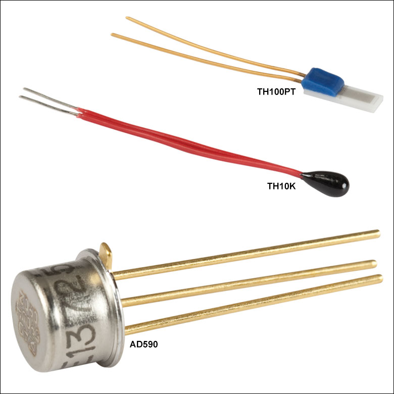
100 Ω Resistance Temperature Detector
(Not to Scale)
TH10K
10 kΩ Thermistor
(Not to Scale)
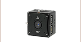
HT15W
Resistive Cartridge Heater
(Not to Scale)
AD590
Temperature Transducer
(Not to Scale)
HT10K
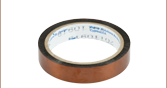
Flexible Resistive Foil Heater
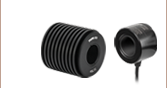
HT19R
Metal Ceramic Heater
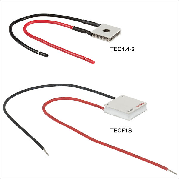
TECF1S
Single-Stage TEC Element
HT10KR2
Metal Ceramic Heater with Thermistor


Please Wait
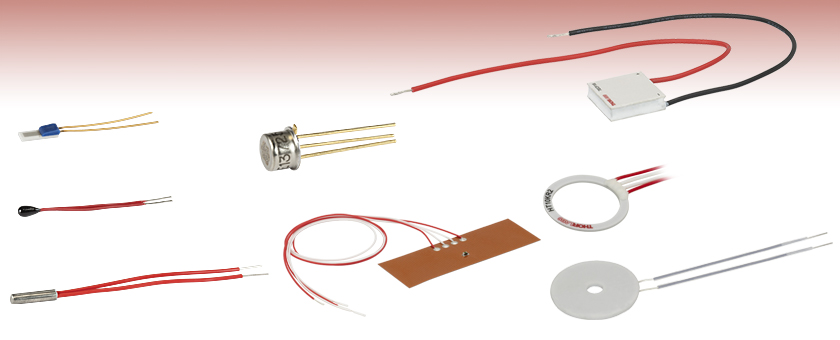
Thorlabs offers a wide range of thermal management accessories, including thermoelectric coolers, resistive heaters, thermistors, and temperature transducers. Thermoelectric coolers can both cool and heat, allowing for quick response to thermal drift or shock. These devices are ideal for total and precise temperature regulation. For applications that require only heating or steady-state regulation slightly above room temperature, resistive heaters are a reliable and easily regulated heat source. Regardless of application, temperature monitoring is essential for any temperature regulation system. Thorlabs' thermistors and thermocouples provide precise and accurate temperature measurements.
Thermoelectric Coolers
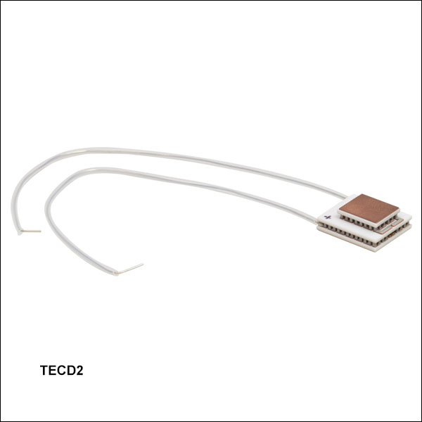
We offer a line of single-stage thermoelectric coolers, which can maintain temperature differentials of at least 73 °C for a 50 °C hot surface. Our dual-stage TEC (Item # TECD2) provides a larger temperature differential between the hot and cold surfaces of the device; when the hot surface is 50 °C, it is capable of maintaining a differential of 108 °C in vacuum. The hot and cold surfaces of the dual-stage TEC are metalized copper for soldering in order to ease integration into the system.
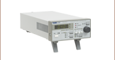
All of our TECs work well with our TED4015 225 W Benchtop Laser Diode Temperature Controller and our rack-mountable temperature controllers, which are designed for the PRO800 Chassis. These TECs can also be driven by our OEM Temperature Controllers in SMT or THT Packages. When using a TEC for thermal regulation, care should be taken to electrically isolate the sides and leads of the TEC.
Resistive Heaters
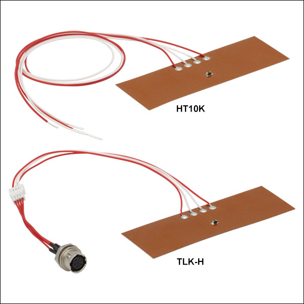
Thorlabs offers four types of resistive heaters: foil, cartridge, metal ceramic, and metal ceramic with thermistor. The HT10K and TLK-H resistive foil heaters have a pressure-sensitive adhesive backing and a 10 kΩ NTC thermistor integrated directly onto the heater. The HT15W heater is a miniature 15 W cartridge heater, which can be used for many applications requiring small areas to be heated. Our metal ceramic heaters come in either round (Item # HT19R) or square (Item #s HT24S and HT24S2) geometries and provide fast thermal response. The HT10KR1, HT10KR2, and HT19R2 metal ceramic heaters have a 10 kΩ thermistor and can reach a maximum temperature of 90 °C. These small but high powered heaters are ideal for thermal regulation of optical components. All of the heaters sold here are compatible with Thorlabs' TC300 heater temperature controller.
Thermistors and Temperature Transducers
We also offer three models of thermistors and temperature transducers. The TH10K is a 10 kΩ thermistor with 1 °C accuracy that is meant to be used in common TEC applications. The TH100PT is a 100 Ω platinum Resistance Temperature Detector (RTD) with a positive linear temperature response. These thermistors are compatible with the TC300 heater temperature controller; the TH10K is compatible with the MTD415T TEC controller in an SMT package. The AD590 is an integrated circuit (IC) temperature transducer with an output current that is proportional to absolute temperature. All our thermistors and AD590 temperature transducers are compatible with the TED200C 12 W Benchtop Laser Diode Temperature Controller and our rack-mountable temperature controllers. For high temperature applications, constantan or manganese wires may be used.
| Posted Comments: | |
图图 Xu
(posted 2023-09-21 16:25:50.77) Which model of temperature controller is the most suitable for the TEC1.4-6 Thermo-Electric Cooler? Do you still need to purchase a TEC control power supply? ksosnowski
(posted 2023-09-25 04:27:53.0) Thanks for reaching out to us. The max current is 6A with a max voltage of close to 2V for this model. To get the full cooling capability of this TEC, a high power driver like our TED4015 may be necessary. If operation at a lower current/voltage point for less cooling is acceptable, then potentially our TED200C or TTC001 drivers may be suitable. We also have some OEM style TEC drivers however for lower powers than those listed here. Our ITC4000 series combination laser/TEC drivers could also drive the TEC1.4-6 to full power. Our benchtop drivers all ship with a region-specific power cable to connect to the wall and TTC001 includes its own power supply adapter as well. Gwiwon Jang
(posted 2023-03-31 09:44:45.85) I'm researcher in sungkyunkwan university in Korea.
can HT24S2 indure vacuum condition?
Can it operate in cryogenic conditions? Is it possible to -100 Celsius degrees? cdolbashian
(posted 2023-04-03 02:17:14.0) Thank you for contacting Thorlabs. From estimation, HT24S2 could be used in -100 C degree. We don’t currently have test data for HT24S2 to be used under vacuum conditions. Our Tech support will reach out to you directly with more discussion. Ajinkya Punjal
(posted 2022-12-23 02:44:50.33) Dear Sir/Ma'am,
I'm Ajinkya from TIFR, Mumbai.
I was looking for a TEC cooler. I wanted to ask whether this TEC is made up of magnetic material. Because I'm looking for TEC which can go to -30degC from room temperature in a 0.5T (max) magnetic field. The TEC should not disturb the magnetic field lines ksosnowski
(posted 2022-12-28 04:09:33.0) Thanks for reaching out to Thorlabs. There are metal contacts inside the TECs, and the current carrying wires leading up to the cooling element would produce local magnetic fields during operation. While our TECs can achieve these low temperatures in the right conditions, it is possible for them to effect the magnetic field. Potentially a liquid coolant solution would be better for eliminating this effect. I have reached out directly to discuss your application in more detail. Jisoo Kyoung
(posted 2022-10-24 22:17:06.157) Dear Thorlabs,
In the overview page, you mention that 'Thermoelectric Cooler (TEC) Elements are Compatible with TC300 Heater Temperature Controller'.
However, it seems that the TC300 Heater Controller is not compatible with any TEC. TC300 Heater Controller only compatible with Resistive heater, isn't it?
Thanks. cdolbashian
(posted 2022-10-31 01:13:10.0) Thank you for contacting Thorlabs. TC300 is indeed compatible with TEC elements. However, at current stage of functionality, the TC300 can only drive the TEC as a heater and does not support the cooling function of a TEC. TED4015 would be a better choice if you require both active heating and cooling applications. Yoo Changhyuk
(posted 2022-04-19 13:32:51.91) Thank you always for your great products. In the CAD file that is provided, the parts that connect the first stage P/N legs and the second stage P/N legs are not shown.
Also, I want to know which leg is a P or N type leg exactly. I wanted to post a picture to explain but unfortunately I can't in this description! I would be very thankful for your replies.
Sincerely, ChanghyukYoo jdelia
(posted 2022-05-12 08:56:05.0) Thank you for contacting Thorlabs. I have reached out to you directly to clarify your inquiry and discuss your application further. user
(posted 2022-02-22 11:25:33.1) Which controller is recommended for the Metal Ceramic Heaters (with and without thermistor)? And how is it possible to connect these elements to the controller since they have just bare wire? ksosnowski
(posted 2022-02-25 06:53:53.0) Thanks for reaching out to us, we recommend the TC300 for controlling the resistive ceramic heaters (both with/without thermistors). You can connect to the TC300 using our cable TC200CAB10. By cutting this cable in half you can solder resistive heaters and thermistors directly to match the TC300 pinout as described on page 6 of the TC300 manual. Gregor A.
(posted 2021-12-17 08:54:23.807) Would be nice if for thermistors like TH10K you had an online calculator to convert between temperature and resistance :-) YLohia
(posted 2021-12-23 01:12:22.0) Hello, thank you for your feedback. We hope to add such functionality to the website in the future. user
(posted 2020-07-23 08:06:27.793) What adhesion should I use to mount TH100PT on HT24S? YLohia
(posted 2020-07-29 10:40:35.0) Thank you for contacting Thorlabs. Thermally conductive epoxies such as the ones listed on this page should be used: https://www.thorlabs.com/newgrouppage9.cfm?objectgroup_id=273. Silver-based thermal pastes would also be acceptable. Nicolas Blando
(posted 2020-01-20 16:22:16.933) Hello,
I am confused about the use of the TEC elements. I would like to use one of these to cool down a thermally isolated metal device inside of a vacuum chamber, I believe the heat load to be in the range of 5-10W and the temperature without cooling reaches roughly 100 deg C. I was hoping you could help me figure out what the optimal solution is, thank your time and help. nbayconich
(posted 2020-01-21 01:59:20.0) Thank you for contacting Thorlabs. When choosing a TEC, it is important to know the heat load, or cooling capacity, of the system (how much heat must be transferred away from the device) and to match that load with a capable TEC. The TEC should be rated for a maximum heat load above that which is emitted by the system, and a sufficiently large heat sink must be attached to the hot surface.
Three equations following are usually used to select a TEC element:
1) ΔT=TH-TC;
2) QH= QC +V*I;
3) TH=R*QH+Tamb;
Where TH and TC represent hot and cold side temperature; QH represents output heat from the TEC; QC represents heat absorbed on the cold side, R represents the heat sink thermal resistance in your system". Output heat from the TEC will be dissipated by the heat sink in your system.
QH equals 10W based on your description. From the equations above to get a rough temperate of TH and ΔT across the TEC. Then we can check the performance curve "Cooling capacity vs. ΔT" of the TEC product which information is published on the web, and find out if the TEC can meet such capacity at the calculated change in Temperature.
We will reach out to you directly to discuss your application. Antonio Benci
(posted 2019-11-14 16:09:18.803) Is this heater vacuum compatible, down to 10^-6 mBar? nbayconich
(posted 2019-11-15 09:36:15.0) Thank you for contacting Thorlabs. We have not yet thoroughly tested these heating elements in vacuum conditions. Our Tech support team will reach out to you directly with more information. Allan McPherson
(posted 2019-10-31 18:28:29.553) Would it be possible to attach this to a curved surface? I need to find a way to cool a Ti:Sapphire crystal that may be housed in a round metal tube. There is some latitude in the diameter of the crystal and its housing, as these will both be custom parts. YLohia
(posted 2019-11-05 08:45:12.0) Thank you for contacting Thorlabs. The TECD2S should be mounted to a flat surface with flatness rated better than +/-0.025 mm over the entire TEC mounting area. The surface should also be clean and free of dirt, oil, scratches, and burrs. We will reach out to you directly to discuss the possibility of mounting to your particular tube. Assaf Manor
(posted 2019-09-22 19:33:59.55) Hello, can the HT10K be connected to an ITC 8052 if ordered without the TLK connector? asundararaj
(posted 2019-09-27 03:24:01.0) Thank you for contacting Thorlabs. The HT10K can be wired with the ITC8052 for heater control, but this is not the recommended process because the temperature control loop could be very unstable. The problem is that a TEC element will heat or cool depending on the polarity of the applied current, while the HT10K will heat for both polarities.
The control loop in the ITC has been designed for TEC elements, i.e. it assumes that one polarity will increase the temperature and the other one will decrease it and the current changes are made accordingly. With the HT10K this is however not true and this can result in an unstable operation. user
(posted 2019-09-12 10:36:53.647) 您好。
我是刘军,来自中国科学院国家授时中心(西安)。请问该款产品可适用于真空环境(真空度为10^-7~10^-8mbar)下吗?或者请您推荐贵公司可拟满足需求的其他型号的产品。
谢谢! YLohia
(posted 2019-09-12 10:17:39.0) Hello, thank you for contacting Thorlabs. A member from our Tech Support team in China (techsupport-cn@thorlabs.com) will reach out to you shortly. Juan Antonio
(posted 2019-03-25 02:05:09.64) Buenas noches
Uso una peltier tech 3s. Me gustaría saber el COP con el que trabaja este tipo de celdas peltier
Me comunico del Instituto Tecnologico deTuxtla Gutiérrez
Saluds nbayconich
(posted 2019-04-01 09:39:26.0) Thank you for contacting Thorlabs. The COP or work efficiency is dependent on the amount of temperature change ΔT required and applied current I of the TEC element. There isn't an exact % efficiency per TEC element as the efficiency will decrease as ΔT increases.
I will contact you directly with more information regarding the change in temperature, cooling capacity and the COP of these TEC elements. regelskis
(posted 2019-02-27 12:07:03.68) What the maximum temperature of hot side (TH) of the Single-Stage TEC Elements is allowed? nbayconich
(posted 2019-03-28 10:30:57.0) Thank you for contacting Thorlabs. We unfortunately do not have a maximum temperature limit of the hot plate itself for these TEC elements. The temperature of the hot plate will be typically limited by the mass of the sample being cooled, ambient temperature of the environment, etc. I would refer to the values of the max allowed temperature difference, heat load, current and voltage to make sure not to exceed either of these specifications.
I will reach out to you directly to discuss your application and needs. abushagur
(posted 2019-01-11 16:27:29.19) I am interested buying the TEC and AD590 sensor, In our facilities we have ITC510 temperature controller, so can I used only for TEC control and not for Laser Diode? second, Do you supply also the circuit board for TEC and sensor connections? so that I just plug and play once I have my sensor mounted on the heat sink>>> My application only to have temperature controllable station..... Thanks for your support nbayconich
(posted 2019-01-18 05:30:11.0) Thank you for contacting Thorlabs. Yes you can use the ITC501 as a temperature controller only and do not need to use the LD current driver outputs.
Several TEC elements we supply can be used with the ITC501 controller as long as the applied voltage to the TEC element you choose does not exceed the ITC501’s compliance voltage and you do not exceed the TEC element’s max heat load, max applied voltage or max temperature specifications.
We do not currently provide circuit boards for these devices at the moment. spiliot
(posted 2017-12-01 09:17:05.387) Should I try to widen the hole of HT19R by a few mms? Will this destroy the heater? nbayconich
(posted 2017-12-29 08:18:51.0) Thank you for contacting Thorlabs. Drilling a larger through hole is not recommended, and we can't guarantee the specs after drilling. A larger hole might damage the ceramic heater. I will reach out to you directly with more information. yt338
(posted 2017-07-04 11:59:42.587) Are your TECs capable of both heating up and cooling down? nbayconich
(posted 2017-07-11 10:35:54.0) Thank you for contacting Thorlabs. Our TEC's are capable of both heating and cooling. The primary purpose of these TEC's is to cool but can be used to heat a device if the hot surface is in contact. For general heating purposes we recommend using our resistive heaters, thermistors and temperature transducers. I will reach out to you directly. raphael.cohen3
(posted 2016-04-14 09:35:01.09) I didn't find which side will be the hot and which the cold for a given voltage input?
Thanks besembeson
(posted 2016-04-14 08:56:36.0) Response from Bweh at Thorlabs USA: The hot side is with the longer length dimensions when wired according to our specified polarity. See the following page: http://www.thorlabs.com/thorcat/4800/TEC3-2.5-SpecSheet.pdf curtis.volin
(posted 2014-05-19 15:07:42.88) I don't see a maximum temperature spec on HT10K or TLK-H. Can you provide this information? myanakas
(posted 2014-05-20 09:06:31.0) Response from Mike at Thorlabs: Thank you for your feedback. The temperature range for the HT10K and TLK-H is -32 to 100 °C (-26 to 212 °F). Based on your feedback this specification has been added to the web presentation for these parts. user
(posted 2014-01-27 04:25:16.06) What is the maximum operational temperature for the HT19R heater element? The heater element HT19R ships with a note saying the maximum is 180 C, while the data sheet online says 400 C. sharrell
(posted 2014-01-27 09:43:26.0) Response from Sean at Thorlabs: Thank you for your pointing out this inconsistency. 400 °C is the correct maximum temperature specification. It appears that the item shipped with an older, incorrect version of the spec sheet; we are working with the production team to get the items in inventory corrected now. jlow
(posted 2012-12-11 17:01:00.0) Response from Jeremy at Thorlabs: The leads on the HT10K are about 13". cbrideau
(posted 2012-12-11 16:05:54.117) How long are the leads on the HT10K? Or can you just solder on your own? tcohen
(posted 2012-10-15 09:25:00.0) Response from Tim at Thorlabs: Thank you for your feedback. We will add the cable as a standalone item shortly (with HIROSE connectors for mating with TC200). For immediate assistance with a compatible cable, please contact us at techsupport@thorlabs.com. cpinyan
(posted 2012-10-10 12:58:44.463) Would be great if Thorlabs also sold connecting cable (connector one end and alligator or other quick clips on other end) to go between Thermistor, heating elements and one of the standard temperature controllers. |

 Zoom
Zoom
Performance specifications are given in the table below as a function of TH, the temperature of the hot surface of the TEC. Imax is the maximum allowed current across the TEC element and Vmax is the maximum allowed voltage difference. These values should not be exceeded. Qmax is the maximum heat load that the TEC can handle; ΔTmax is the maximum temperature difference between the hot and cold surfaces of the TEC in a dry nitrogen environment.
When choosing a TEC, it is important to know the heat load, or cooling capacity, of the system (how much heat must be transferred away from the device) and to match that load with a capable TEC. The TEC should be rated for a maximum heat load above that which is emitted by the system, and a sufficiently large heat sink must be attached to the hot surface. Proper thermal contact is necessary for optimal heat transfer. Ensuring that the TEC is of the proper size for the system is important as well as using thermal tape or grease to help facilitate heat transfer. It is important to note that the heat transfer efficiency is affected by the ambient environment; care must be taken to avoid condensation on the cold side. Large changes in background temperature or significant humidity can hamper heat flow. These factors should be taken into account when choosing an appropriate TEC.
All the TECs available here, with the exception of the TEC3-2.5, TEC3-6, and TEC1.4-6, are silicone sealed to protect the core from moisture and condensation.
We offer several kinds of temperature controllers for our TECs. The TED4015 225 W TEC Controller is a benchtop laser diode temperature controller with excellent temperature stability. Our rack-mountable temperature controllers are also capable of excellent temperature stabilization and additionally are compatible with the PRO800 Chassis. For OEM, custom, or embedded systems, we offer OEM Temperature Controllers in SMT or THT Packages as well as on a PCB with mounting standoffs.
| Item # | Imax | TH = 27 °C | TH = 50 °C | AC Resistance | Dimensions (See Above Diagram) |
Performance Graphs |
||||||||
|---|---|---|---|---|---|---|---|---|---|---|---|---|---|---|
| Qmax | Vmax | ΔTmax | Qmax | Vmax | ΔTmax | @ 30 °C | A | B | C | D | E | |||
| TECF1S | 1.2 A | 6.0 W | 7.0 V | 68.8 °C | 6.7 W | 7.9 V | 77.9 °C | 6.50 Ω | 18.0 mm (0.71") |
18.0 mm (0.71") |
18.0 mm (0.71") |
4.9 mm (0.19") |
N/A | |
| TECF2S | 1.9 A | 9.7 W | 8.2 V | 66.4 °C | 11.5 W | 9.1 V | 73.8 °C | 3.30 Ω | 18.0 mm (0.71") |
18.0 mm (0.71") |
18.0 mm (0.71") |
3.4 mm (0.13") |
N/A | |
| TECD2S | 2.1 A | 5.1 W | 3.7 V | 65.8 °C | 5.7 W | 4.2 V | 74.7 °C | 1.50 Ω | 12.0 mm (0.47") |
12.0 mm (0.47") |
12.0 mm (0.47") |
3.4 mm (0.13") |
N/A | |
| TEC3-2.5 | 2.5 A | 6 W | 3.6 V | 65 °C | 6 W | 4.1 V | 73 °C | 1.2 Ω @ 27 °C | 20.5 mm (0.807") |
16.0 mm (0.630") |
16.0 mm (0.630") |
4.0 mm (0.159") |
N/A | |
| TECH3S | 3.7 A | 35.3 W | 14.3 V | 64.8 °C | 36.2 W | 15.3 V | 74.0 °C | 3.80 Ω | 30.0 mm (1.18") |
30.0 mm (1.18") |
30.0 mm (1.18") |
3.2 mm (0.13") |
N/A | |
| TECL4 | 3.8 A | 77.1 W | 32.3 V | 68.5 °C | 85.6 W | 35.6 V | 76.4 °C | 6.00 Ω | 50.0 mm (1.97") |
50.0 mm (1.97") |
50.0 mm (1.97") |
5.3 mm (0.21") |
N/A | |
| TECH4 | 4.6 A | 44.8 W | 15.2 V | 66.3 °C | 48.2 W | 16.6 V | 75.7 °C | 2.50 Ω | 40.0 mm (1.57") |
40.0 mm (1.57") |
40.0 mm (1.57") |
3.8 mm (0.15") |
N/A | |
| TEC3-6 | 5.6 A | 13.0 W | 3.6 V | 65 °C | 14.0 W | 4.1 V | 73 °C | 0.50 Ω @ 27 °C | 24.6 mm (0.969") |
20.1 mm (0.791") |
20.1 mm (0.791") |
3.91 mm (0.154") |
N/A | |
| TECJ6 | 5.9 A | 87.9 W | 23.5 V | 67.7 °C | 103.5 W | 26.2 V | 76.1 °C | 3.25 Ω | 40.0 mm (1.57") |
40.0 mm (1.57") |
40.0 mm (1.57") |
4.1 mm (0.16") |
N/A | |
| TECD6 | 6.0 A | 14.1 W | 3.6 V | 66.0 °C | 15.1 W | 3.9 V | 74.5 °C | 0.45 Ω | 20.0 mm (0.79") |
20.0 mm (0.79") |
20.0 mm (0.79") |
3.8 mm (0.15") |
N/A | |
| TEC1.4-6 | 6.0 A | 6 Wb | 1.7 Vb | 67 °Cb | 6.6 W | 1.9 V | 75 °C | 0.27 Ω @ 25 °C | 14.2 mm (0.560") |
14.2 mm (0.560") |
14.2 mm (0.560") |
3.8 mm (0.150") |
Ø5.0 mm (Ø0.20") |
|
| TECJ8 | 7.8 A | 123.2 W | 23.6 V | 66.6 °C | 145.8 W | 27.8 V | 74.5 °C | 2.40 Ω | 40.0 mm (1.57") |
40.0 mm (1.57") |
40.0 mm (1.57") |
3.7 mm (0.15") |
N/A | |
| TECH8 | 8.5 A | 75.6 W | 14.2 V | 66.2 °C | 84.2 W | 15.7 V | 75.0 °C | 1.50 Ω | 40.0 mm (1.57") |
40.0 mm (1.57") |
40.0 mm (1.57") |
3.5 mm (0.14") |
N/A | |
| TECH11 | 11.7 A | 101.0 W | 13.5 V | 66.4 °C | 110.0 W | 15.0 V | 75.5 °C | 1.05 Ω | 40.0 mm (1.57") |
40.0 mm (1.57") |
40.0 mm (1.57") |
3.2 mm (0.13") |
N/A | |
| TECD14 | 13.2 A | 31.8 W | 3.8 V | 72.0 °C | 34.0 W | 4.2 V | 75.0 °C | 0.23 Ω | 30.0 mm (1.18") |
30.0 mm (1.18") |
30.0 mm (1.18") |
3.9 mm (0.15") |
N/A | |

 Zoom
Zoom
Click for Details
Dual-Stage TEC Dimensional Drawing
| Specification | Value | Test Conditions (Vacuum) |
|---|---|---|
| Imax | 2.4 A | Q = 0 W, ΔT = 108 °C, TH = 50 °C |
| Vmax | 9.2 V | Q = 0 W, I = 2.4 A, TH = 50°C |
| ΔTmax | 108 °C | Q = 0 W, I = 2.4 A, TH = 50 °C |
| Qmax | 5.6 W | I = 2.4 A, ΔT = 0 °C, TH = 50°C |
| TH,max | 200 °C | - |
| Resistance | 2.664 - 3.251 Ω | 25 °C Ambient Temperature |
| Flatness / Parallelism of Two Faces | ≤0.10 mm | - |
Our Dual-Stage Thermoelectric Cooler (TEC) is ideal for situations where additional cooling is required. The TECD2 provides a temperature difference between the hot and cold surfaces of up to 108 °C when the hot surface is at 50 °C. The hot and cold surfaces are metalized copper to allow for soldering. This TEC is designed to operate in vacuum levels of 10-6 Torr with proper cleaning and bake out.
The performance values for our Dual-Stage TEC is given as a function of TH, the temperature of the hot surface of the TEC. Imax is the maximum allowed current across the TEC element and Vmax is the maximum allowed voltage difference. These values should not be exceeded. Qmax is the maximum heat load that the TEC can handle; ΔTmax is the maximum temperature difference between the hot and cold surfaces of the TEC in vacuum.
When choosing a TEC, it is important to know the heat load of the system (how much heat must be transferred away from the device) and to match that load with a capable TEC. The TEC should be rated for a maximum heat load above that which is emitted by the system, and a sufficiently large heat sink must be attached to the hot surface. Proper thermal contact is necessary for optimal heat transfer. Ensuring that the TEC is of the proper size for the system is important as well as using thermal tape or grease to help facilitate heat transfer. It is important to note that the heat transfer efficiency is affected by the ambient environment; care must be taken to avoid condensation on the cold side. Large changes in background temperature or significant humidity can hamper heat flow. These factors should be taken into account when choosing an appropriate TEC.
We offer three kinds of temperature controllers for our TECs. The TED4015 225 W TEC Controller is a benchtop laser diode temperature controller with excellent temperature stability. Our rack-mountable temperature controllers are also capable of excellent temperature stabilization and additionally are compatible with the PRO800 Chassis. For OEM, custom, or embedded systems, our OEM Temperature Controllers are available in SMT or THT Packages.

 Zoom
Zoom| Item # | HT10K | TLK-H |
|---|---|---|
| Heater Power | 10 W/in2 (0.016 W/mm2) @ 70 °C | |
| Heater Resistance | 19.7 Ωa | |
| Sensor Type | NTC10K Thermistor | |
| Size | 1" x 3" (25.4 mm × 76.2 mm) | |
| Effective Heating Area | 2.23 in2 (1438.7 mm2) | |
| Minimum Bend Radius | 0.5" (12.7 mm) in Thermistor Area, 0.030" (0.8 mm) in All Other Areas |
|
| Temperature Range | -32 to 100 °C (-26 to 212 °F) | |
| Connector Type | Bare Wire Leads | 6-Pin Hirose HR10A-7R-6S |
| Simplified Drawing and Pin Diagram |  |
 |
| Compatible Controller | TC300b | |
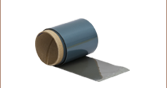
- Kapton (Polyimide) Foil Heaters with Integrated Thermistors
- 1" x 3" (25.4 mm x 76.2 mm) Heating Area
- Adhesive Backing for Easy Installation
- 10 W/in2 (0.016 W/mm2) Heating Capacity
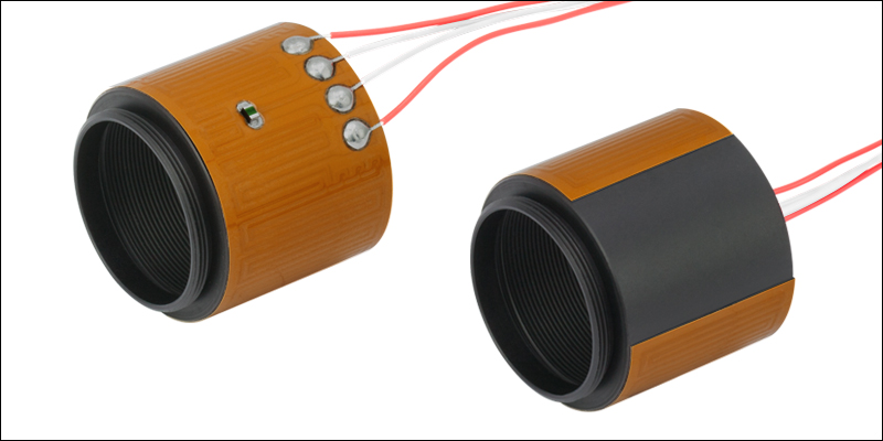
These 1" x 3" (25.4 mm x 76.2 mm) foil heating elements are useful for many lab applications. They have an integrated thermistor for closed-loop temperature control and an acrylic pressure-sensitive adhesive backing for easy installation. Both models use the same Kapton (polyimide) heating element and 10 kΩ negative temperature coefficient (NTC) thermistor.
The HT10K features bare wire leads for use with a user-provided connector. Alternatively, the
Both foil heaters are flexible for use in applications such as heating lens tubes, as shown in the photo to the right. In this application, the lens tube can be isolated from the rest of the system using a Thermally Insulating Adapter.

 Zoom
Zoom| Item # | HT15W |
|---|---|
| Heater Resistance | 27.6 Ω (Min) 41.1 Ω (Max) |
| Size | Ø0.122" x 1/2" (Ø3.1 mm x 12.7 mm) |
| Heater Power | 15 W @ 24 V |
| Maximum Temperature | 500 °F (260 °C)a |
| Connector Type | Bare Leads |
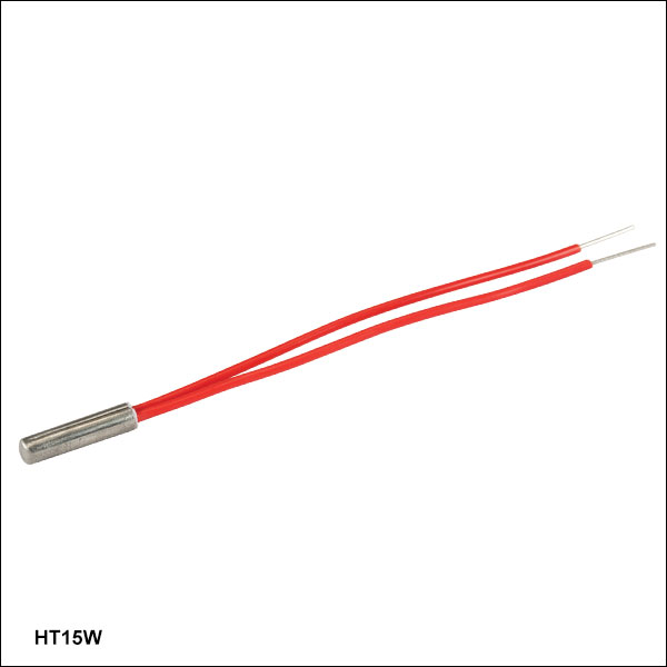
- General Purpose Cartridge-Type Resistive Heater
- Compact Ø0.122" x 1/2" (Ø3.1 mm × 12.7 mm) Cylindrical Package
- 15 W Nominal Heater Power
The HT15W is a 15 W cartridge-shaped resistive heater with bare leads. It has a nominal heater power of 15 W at 24 V, and a maximum temperature of 500 °F (260 °C). It is compatible with our TC300 Heater Temperature Controller.

 Zoom
Zoom| Item # | HT19R | HT24S | HT24S2 |
|---|---|---|---|
| Heater Power | 19 W @ 24 V 4.8 W @ 12V 1.2 W @ 6 V |
24 W @ 24 V 6.1 W @ 12 V 1.5 W @ 6 V |
|
| Heater Resistance | 30 Ω ± 10% | 23.5 Ω ± 10% | |
| Dimensions | Ø23.0 mm (Ø0.906") O.D. Ø4.1 mm (Ø0.161") I.D. |
20.0 mm (0.787") Square | 28.0 mm (1.102") Square |
| Dimensional Tolerance | ±0.5 mm (0.02") O.D. ±0.15 mm (0.006") I.D. |
±0.5 mm (0.02") | |
| Thickness | 1.3 mm (0.05") | 1.7 mm (0.067") | |
| Thickness Tolerance | ±0.1 mm (0.004") | ||
| Lead Length | 50.0 mm (1.97") | ||
| Max Temperature | 400 °C | ||

 Zoom
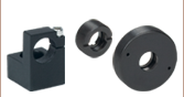
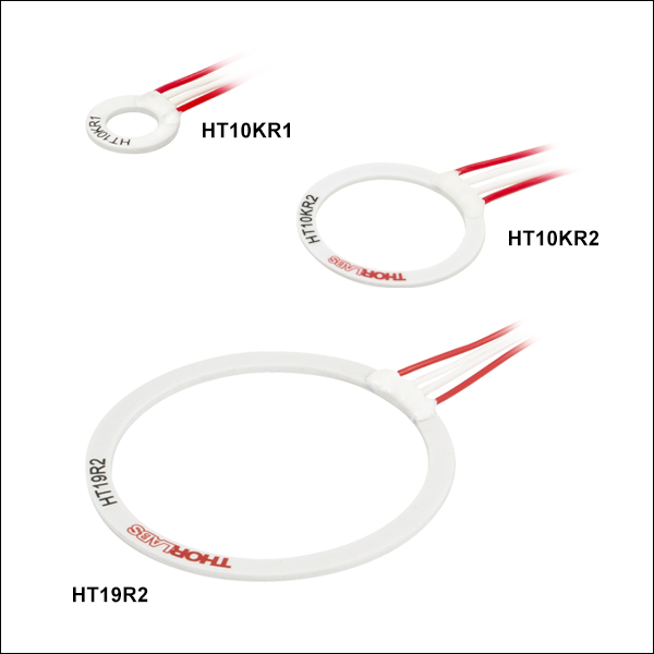
Zoom- General Purpose Metal Ceramic Heaters with 10 kΩ Thermistors
- HT10KR1: 10 W, 12.4 mm Outer Diameter
- HT10KR2: 10 W, 24.9 mm Outer Diameter
- HT19R2: 19 W, 50.0 mm Outer Diameter
These Metal Ceramic Ring Heaters contain 10 kΩ thermistors. The heaters have four leads: two red leads for the heater, and two white ones for the thermistor. The HT10KR2 Ø24.9 mm heater is also compatible with our threaded glass cells. All the heaters can be used with the TC300 Heater Temperature Controller.
| Item # | Heater Power (@ 24 V) |
Heater Resistance |
Outer Diameter |
Inner Diameter |
Thicknessa | Thermistor Model (10 kΩ) |
R0b, B25/100 |
Lead Length |
Max Temperature |
|---|---|---|---|---|---|---|---|---|---|
| HT10KR1 | 10 W ± 20% | 50 Ω ± 10% | 12.4 mm ± 0.3 mm (0.49" ± 0.012") |
7.2 mm ± 0.25 mm (0.28" ± 0.010") |
1.0 mm ± 0.1 mm (0.04" ± 0.004") |
TDK B57230V2103F260 | 10 kΩ ± 1%, 3455 K ± 1% |
305.0 mm +10/-0.0 mm (12.01" +0.4/-0.0") |
90 °C |
| HT10KR2 | 10 W ± 20% | 50 Ω ± 10% | 24.9 mm ± 0.5 mm (0.98" ± 0.02") |
20.0 mm ± 0.5 mm (0.79" ± 0.02") |
1.0 mm ± 0.1 mm (0.04" ± 0.004") |
||||
| HT19R2 | 19 W ± 20% | 30 Ω ± 10 % | 50.0 mm ± 0.5 mm (1.97" ± 0.02") |
43.0 mm ± 0.5 mm (1.69" ± 0.02") |
1.3 mm ± 0.3 mm (0.051" ± 0.009") |

 Zoom
Zoom| AD590 | |
|---|---|
| Linear Current Output | 1 µA / K |
| Operating Range | -55 °C to 150 °C |
| Power Supply Range | 4 to 30 V |
| Bottom View (Click to Enlarge) |
 |
| TH10Ka | |
|---|---|
| Temp. Accuracy | ±1 °C |
| Dissipation Constant | 1.4 mW/°C |
| Time Constant | 15 s |
| Operating Range | -50 to 150 °C |
| Temp. Coefficient | -4.40 %/°C |
| TH100PT | |
|---|---|
| Rating | 100 Ω @ 0 °C |
| Temp. Coefficient | 3.85 x 10⁻³ / K |
| Accuracy | Class B Tolerance (±0.3 °C @ 100 Ω) |
| Operating Range | -70 to 400 °C (-94 to 752 °F) |