 Products Home
High-Precision Rotation Stage
- Continuous 360° Manual Rotation
- Micrometer and Vernier Scale Provide 5 arcmin Resolution
- Mount Horizontally or Vertically
Ø0.94" (Ø23.9 mm) Clear
Aperture with SM1 Threading
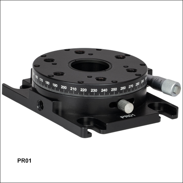
PR01
Cube Beamsplitter on
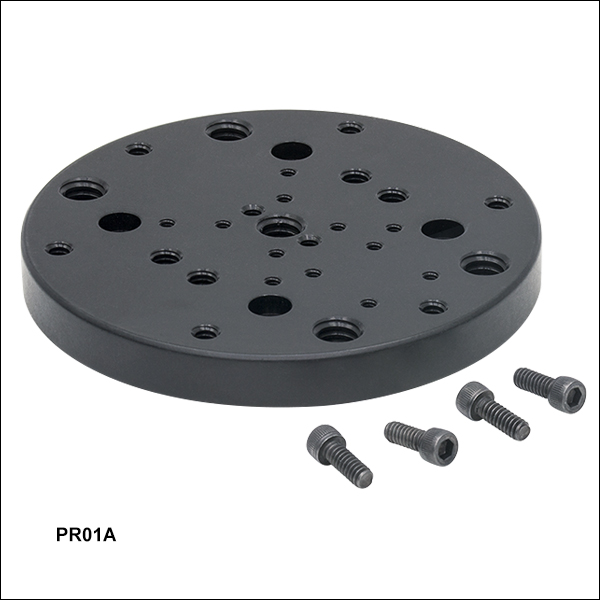
PR01A Adapter Plate,
Held with PM4 Clamping Arm


Please Wait
| Specifications | ||
|---|---|---|
| Item # | PR01(/M) | |
| Coarse Rotation Range | 360°, Continuous | |
| Fine Adjustment Range | ±5° | |
| Clear Aperture | Ø0.94" (Ø23.9 mm) | |
| Horizontal Load Capacity |
Overall: 25 lbs (11.4 kg) Fine Adjustment: 3.75 lbs (1.7 kg) |
|
| Vertical Torque Capacitya | 8.28 lb-in (0.93 N·m) | |
| Platform Dimension | Ø2.7" (Ø68.6 mm) | |
| Platform Mounting Holes |
1/4"-20 (M6) (6 Places) 6-32 (M4) (10 Places) 4-40 (4 Places) |
|
| Platform Height | 1.0" (25.3 mm) | |
| Base Dimensions | 2.75" x 3.5" (69.9 mm x 88.9 mm) | |
| Base Mounting Features | Mounting Slot for 1/4"-20 (M6) Cap Screws (4 Places) |
|
| 1/4"-20 (M6) Taps for Vertical Mounting (2 Places) |
||
and ±5° of fine rotation.
Features
- 360° of Continuous Coarse Rotation
- Micrometer and Vernier Scale Provide ±5° Fine Adjustment
- Perimeter is Laser Engraved at 1° Increments
- Tapped Holes for Standard Optomechanics, Clamping Arms, or Rods for 30 mm Cage Systems
- Center Hole is SM1 Threaded (1.035"-40)
- Mounting Adapters Available for Optics, Translation Stages, Goniometers, and Rotating Cage Systems
- 25 lbs (11.4 kg) Load Capacity
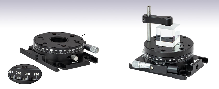
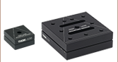
Thorlabs' PR01(/M) High-Precision Rotation Stage provides precise, fine rotation for large optics and optomechanical assemblies. As shown in the animation to the right, if the steel locking thumbscrew is unlocked, the stage can be smoothly and continuously rotated by hand through a full 360°, measured by the 1° graduation marks on the side of the stage. When the thumbscrew is locked, the micrometer provides ±5° of fine adjustment, measured with 5 arcmin resolution by the vernier scale.
As shown to the right, the rotation stage features an array of 1/4"-20 (M6), 6-32 (M4), and 4-40 tapped holes, designed for standard optomechanics, our clamping arms (sold below), or our 30 mm cage systems. It attaches to an optical table or breadboard using the four 1/4" (M6) counterbored clearance slots.
Solid Adapter Plate
For applications that benefit from having a rotation platform without a hole, we offer the PR01A(/M) Adapter Plate. It attaches to the top of the PR01(/M) rotation stage and provides a tapped hole array designed for compatibility with our 1- and 2-axis goniometers and our miniature translation stages. As shown in the image at the top of the page, it is also well suited for holding optics in combination with a clamping arm.
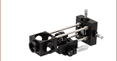
Rotation Adapter for 30 mm Cage Systems
This adapter is designed to hold two 30 mm cage rods in a plane perpendicular to the axis of rotation. In combination with the PR01(/M) rotation stage , it allows a 30 mm cage segment to be rotated through a full 360° and precisely aligned using the stage's micrometer.
Click to Enlarge
Figure 1: An example of how to read a vernier scale. The red arrow indicates what is known as the pointer. Since the tick mark labeled 10 on the vernier scale aligns with one of the tick marks on the main scale, this vernier scale is reading 75.60 (in whatever units the tool measures).
Reading a Vernier Scale
Vernier scales are typically used to add precision to standard, evenly divided scales (such as the scale on Thorlabs' rotation mounts). A vernier scale has found common use in many precision measurement tools, the most common being calipers and micrometers. The direct vernier scale uses two scales side-by-side: the main scale and the vernier scale. The vernier scale has a slightly smaller spacing between its tick marks (10% smaller than the main). Hence, the lines on the main scale will not line up with all the lines on the vernier scale. Only one line from the vernier scale will match well with one line of the main scale, and that is the trick to reading a vernier scale.
Figures 1 through 3 show a vernier scale system for three different situations. In each case, the scale on the left is the main scale, while the small scale on the right is the vernier scale. When reading a vernier scale, the main scale is used for the gross number, and the vernier scale gives the precision value. In this manner, a standard ruler or micrometer can become a precision tool.
The 0 on the vernier scale is the "pointer" (marked by a red arrow in Figs. 1 - 3) and will indicate the main scale reading. In Figure 1 we see the pointer is lined up directly with the 75.6 line. Notice that the only other vernier scale tick mark that lines up well with the main scale is 10. Since the vernier 0 lines up with the main scale’s 75.6, the reading from Figure 1 is 75.60 (in whatever units the tool measures in).
That is essentially all there is to reading a vernier scale. It's a very straightforward way of increasing the precision of a measurement tool. To expound, let’s look at Figure 2. Here we see that the pointer is no longer aligned with a scale line, instead it is slightly above 75.6, but below 75.7; thus the gross measurement is 75.6. The first vernier line that coincides with a main scale line is the 5, shown with a blue arrow. The vernier scale gives the final digit of precision; since the 5 is aligned to the main scale, the precision measurement for Figure 2 is 75.65.
Since the vernier scale is 10% smaller than the main scale, moving 1/10 of the main scale will align the next vernier marking. This asks the obvious question: what if the measurement is within the 1/10 precision of the vernier scale? Figure 3 shows just this. Again, the pointer line is in between 75.6 and 75.7, yielding the gross measurement of 75.6. If we look closely, we see that the vernier 7 (marked with a blue arrow) is very closely aligned to the main scale, giving a precision measurement of 75.67. However, the vernier 7 is very slightly above the main scale mark, and we can see that the vernier 8 (directly above 7) is slightly below its corresponding main scale mark. Hence, the scale on Figure 3 could be read as 75.673 ± 0.002. A reading error of about 0.002 would be appropriate for this tool.
As we've seen here, vernier scales add precision to a standard scale measurement. While it takes a bit of getting used to, with a little practice, reading these scales is fairly straightforward. All vernier scales, direct or retrograde, are read in the same fashion.
Click to Enlarge
Figure 2: An Example of a vernier scale. The red arrow indicates the pointer and the blue arrow indicates the vernier line that matches the main scale. This scale reads 75.65.
Click to Enlarge
Figure 3: An Example of a vernier scale. The red arrow indicates the pointer and the blue arrow indicates the vernier line that matches the main scale. This scale reads 75.67, but can be accurately read as 75.673 ± 0.002.
| Posted Comments: | |
Marcin Sleczka
(posted 2022-04-27 12:15:39.133) Dear Thorlabs Crew,
I have notice that with the PRO1A/M stage four screws with metric thread but for imperial hex key are included.
It is surprising for me. I do not have such key because I use metric standard.
Best regards,
Marcin jdelia
(posted 2022-05-12 03:25:35.0) Thank you for contacting Thorlabs. The four screw that come with the PR01A/M are imperial 4-40 screws to mate with the 4-40 mounting holes on the PR01(/M). The reasoning behind this is so that the stage is compatible with our 4-40 threaded ER- series cage rods. We than you for bringing to the light the issue that it is difficult to adjust these screws if you only have metric hex keys, and apologize for the inconvenience you are experiencing. We have reached out to you directly regarding potential solutions. Rajeev Sharma
(posted 2021-10-26 14:14:28.27) Hi,
Greetings from Keysight Technologies!
There is no RoHS CoC available for this part on your website. Could you please provide RoHS CoC as per directive 2015/863? Thanks!
Regards,
Rajeev Sharma YLohia
(posted 2021-12-23 10:50:12.0) Hello Rajeev, thank you for contacting Thorlabs and bringing this to our attention. I have reached out to you directly with a pdf of the RoHS and we have updated the webpage to include this information. Edmond Chehura
(posted 2019-07-26 07:31:47.68) Is it possible to replace the manual micro-adjuster with a motorized actuator? If so, which motorized actuator? YLohia
(posted 2019-07-26 11:18:01.0) Thank you for contacting Thorlabs. Unfortunately, this stage cannot be motorized. We recommend using the HDR50 for such applications. If your load is very light, you can use the PRM1Z8. david.sommitz
(posted 2018-07-25 15:43:54.193) These are great for making relative angular measurements! Is there any way to adjust the absolute rotation state so that a reading of 0 degrees on the instrument is parallel/perpendicular to one of the three sets of 1/4-20 holes? The absolute position seems arbitrary as is. llamb
(posted 2018-07-27 05:55:47.0) Thank you for your feedback. The main rotating body of the PR01 is designed so that the 0°/180° engravings line up with the center line of 1/4"-20 and #6-32 holes. Refer to the PR01(/M) schematic image where the two pairs of holes are aligned vertically and would match the 0°/180° engravings on the side. You can fine adjust your micrometer to your desired "0" position while the PR01(/M) is locked, and then while unlocked you can manually adjust the stage to align the 0 engraving where needed. chrisb
(posted 2018-07-02 21:59:26.087) What is the Backlash for this stage? llamb
(posted 2018-07-13 02:24:59.0) Thank you for contacting Thorlabs. The PR01(/M) stage will not have any backlash for coarse adjustment, as the mounting platform rotates about an internal ring. Fine adjustment is driven by our 148-206ST micrometer which uses a fine adjustment screw. Because this micrometer's adjustment screw is preloaded by a spring force, fine adjustment will have negligible backlash. kwon0512
(posted 2017-10-24 16:58:55.843) Hi,
What is difference between CR1 and PR01A tfrisch
(posted 2017-10-30 02:00:24.0) Hello, thank you for contacting Thorlabs. The biggest functional difference is that CR1 uses a worm gear for travel and a vernier scale to achieve 10arcsec resolution where the PR01 (the stage used with the PR01A top plate) is directly rotated by hand for coarse adjustment and uses a micrometer with 2.4arcsec resolution for the fine adjustment. I will reach out to you directly to discuss these stages further. skooi
(posted 2017-06-09 10:52:39.85) Hi,
If I put a longer travel distance micrometer on this stage, would I be able to get a greater range of precision angles? I would like a longer that +-5 degrees of high precision travel.
Thanks,
Steve. tfrisch
(posted 2017-06-22 04:22:28.0) Hello, thank you for contacting Thorlabs. While PR01 is not compatible with a larger micrometer, the vernier scale can be used to finely measure the position at any point in the rotation of the stage. This will require coarse adjustment between ranges, but the position can then be finely set. I will reach out to you directly to discuss your application. cadatte
(posted 2015-04-09 15:55:06.82) Hello,
I would like to use the unit outside, even if it is raining. Will the unit support water?
Thank you, Cyril jlow
(posted 2015-04-14 11:30:40.0) Response from Jeremy at Thorlabs: The rotation mount is not sealed to be waterproofed so water could get into the internal components of the mount. This will degrade the grease used inside and you will probably not get smooth movement. It will also potentially expose the internal components to corrosion. medmonds
(posted 2015-03-30 18:15:02.957) Hello,
Is there a users manual for this rotational stage? The mounting scheme and the adjustments seem skewed and difficult for some people using this. The zero point seems to be in an odd place. People are wondering whats the standard intended use and setup. Any information is appreciated.
Thanks
Mike cdaly
(posted 2015-03-31 01:53:44.0) Response from Chris at Thorlabs: I'm afraid there is no manual for the PR01(/M), but hopefully this explanation will provide enough clarity. The rotating platform in the middle is free to rotate manually when the thumbscrew is unlocked. Threading down the thumbscrew secures the rotating platform to an interior moving ring. This ring has a small level arm attached which is mounted between a compression spring and linear micrometer. Moving the micrometer in or out will push on this arm, rotating the ring inside. When the thumbscrew is tightened this will in-turn move the rotating platform along with the ring. The location of the zero position when using the micrometer driven fine adjustment is dependent on where the rotating platform was manually positioned before the thumbscrew was locked down. This course adjustment, the manual movement of the platform without the thumbscrew locked down can be done over a continuous 360 degree range, while the fine adjustment can only be used over a +/- 5 degree range. h.vennekate
(posted 2014-09-12 07:59:04.567) I'm not quite sure how the calibration of the micrometer's graduations to the vernier scale is gonna work out. Can you give any more detailed advice on that one? jlow
(posted 2014-09-18 03:58:27.0) Response from Jeremy at Thorlabs: The angular rotation is not linear with the linear translation of the micrometer. You would have to record the amount of rotation for a number of distances the micrometer has moved and then fit a curve onto the points you recorded. We will contact you directly to discuss more about this. patrick.hallen
(posted 2014-05-16 11:19:58.073) We are planning to use the PR01/M in a vertical configuration and want to attach a rather heavy setup to it. What is the torque limit of the PR01/M (i.e. what is the limit for the vertical attachment of heavy/large objects). cdaly
(posted 2014-05-22 11:53:27.0) Response from Chris at Thorlabs: The torque limit of the stage is 0.69 foot pounds (0.93 N m). It is intended to have the center of mass as close as possible to the center of rotation. marek.mikloska
(posted 2014-05-15 16:36:51.173) Is it possible to use this mount in production environment - CNC machine ? It would be exposed to leaking of coolant - ispoarafinic hydrocarbon spraymist mixed with germanium dust. Is it possible to mount GNL18/M - Large Goniometer on this rotational stage ? Thank you for your answer. Marek cdaly
(posted 2014-05-22 10:34:03.0) Response from Chris at Thorlabs: The GNL18/M can be mounted to the metric stage PR01/M. You can use M6 cap screws through the 50 mm separated slots on the goniometer and into any two opposing M6 holes on the platform of the PR01/M. There will only be one screw in each slot, so you will need to align it manually if you want this centered about the axis of rotation. As for the environment, I cannot recommend using this when there is a strong possibility of getting debris into the inner workings of the stage. petr.hlavenka
(posted 2013-12-02 05:06:03.58) Please can you specify the wobble (or paralellism) and concentricity over 360deg rotation. Is its the same as for CR1/M-Z7 model?
Thanks,
Petr cdaly
(posted 2013-12-05 10:08:21.0) Response from Chris at Thorlabs: Thank you for using the feedback tool. The worst case parallelism from the mounting surface to the rotation dial is – 0.001”. The worst case potential wobble of the rotation dial to the mounting plate is 2mrad. Worst case concentrically of the dial to the mounting plate would be 0.00075". Throlabs
(posted 2010-07-23 11:10:25.0) Response from Javier at Thorlabs to andrgrimes: Thank you very much for your feedback. I will discuss your comments with our mechanics department. We are constantly looking to improve our products, so we will certainly take this into account when designing a new version of the PR01 rotation stage. andrgrimes
(posted 2010-07-22 12:42:17.0) This is a very poorly designed product below are a list of faults I saw when trying to use the PR01.
1. The locking screw is in a bad place and too small and cheap feeling, making it very hard to lock this stage in place.
2. This product is listed as a related product in the goniometer section, how ever the awkward mounting dimensions for both of them did not allow for the goniometer and rotation stage to be mounted on the same axis.
3. The micrometer has a substantial amount of wind up making it difficult to make precise adjustments around a point.
4. The mounting slots are at an awkward 2 1/2" x 3" and they are slotted making it difficult to mount vertically.
Overall this product leads to many headaches when setting up and disappointment when it is set up you realize that it does not work as expected. The Newport rotation stages are much better in every way possible. |
Rotation Mount and Stage Selection Guide
Thorlabs offers a wide variety of manual and motorized rotation mounts and stages. Rotation mounts are designed with an inner bore to mount a Ø1/2", Ø1", or Ø2" optic, while rotation stages are designed with mounting taps to attach a variety of components or systems. Motorized options are powered by a DC Servo motor, 2 phase stepper motor, piezo inertia motor, or an Elliptec™ resonant piezo motor. Each offers 360° of continuous rotation.
Manual Rotation Mounts
| Rotation Mounts for Ø1/2" Optics | |||||||
|---|---|---|---|---|---|---|---|
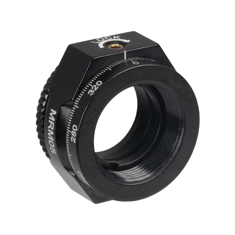
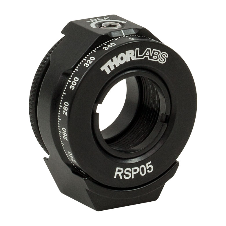
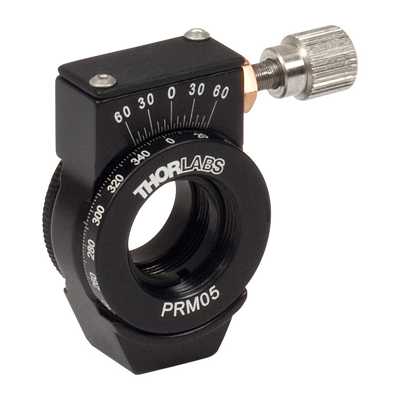
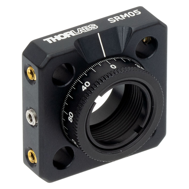
| Item # | MRM05(/M) | RSP05(/M) | CRM05 | PRM05(/M)a | SRM05 | KS05RS | CT104 |
| Click Photo to Enlarge |
 |
 |
 |
 |
 |
 |
 |
| Features | Mini Series | Standard | External SM1 (1.035"-40) Threads |
Micrometer | 16 mm Cage-Compatible | ±4° Kinematic Tip/Tilt Adjustment Plus Rotation | Compatible with 30 mm Cage Translation Stages and 1/4" Translation Stagesb |
| Additional Details | |||||||
| Rotation Mounts for Ø1" Optics | ||||||||
|---|---|---|---|---|---|---|---|---|
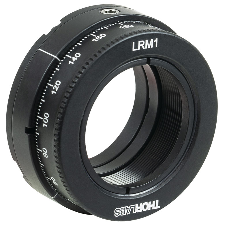
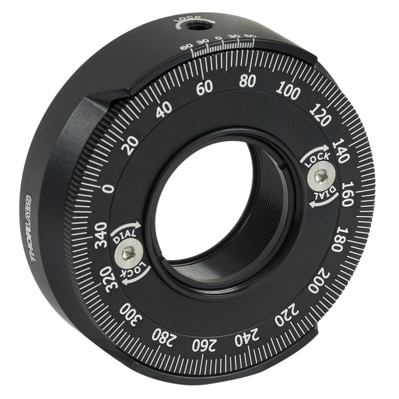
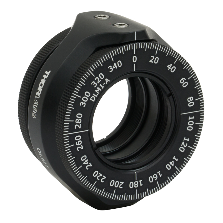
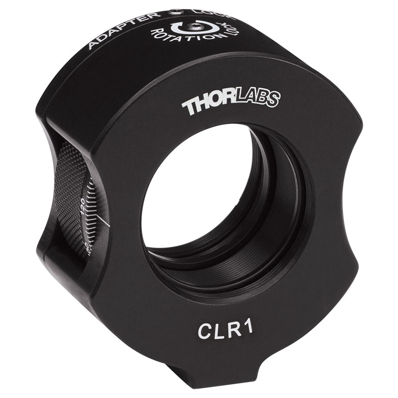
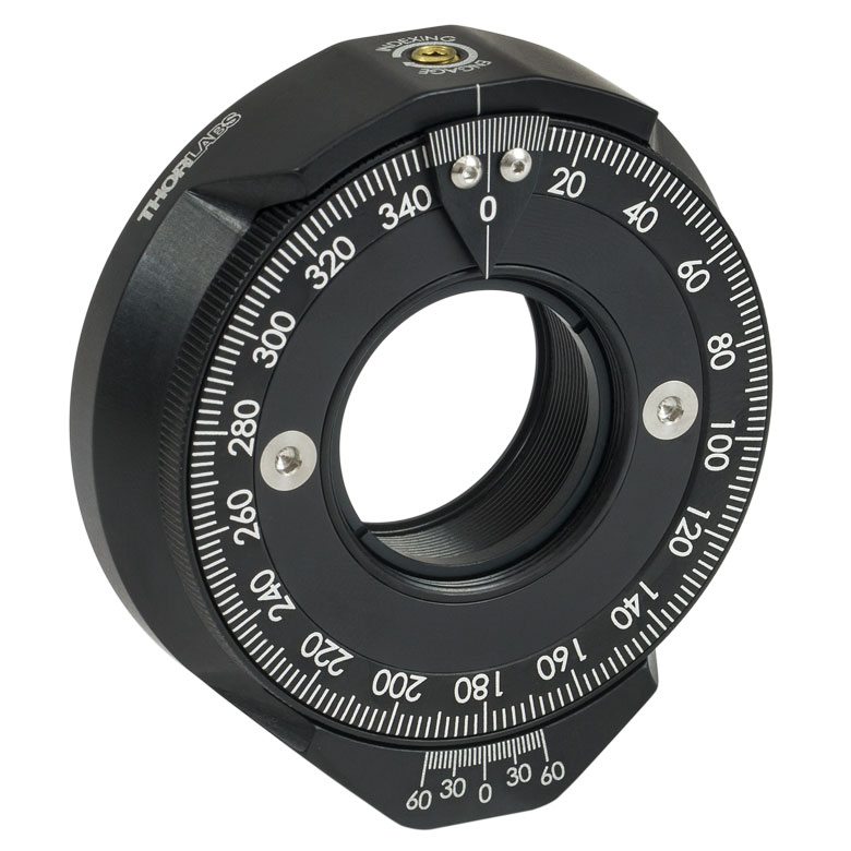
| Item # | RSP1(/M) | LRM1 | RSP1D(/M) | DLM1(/M) | CLR1(/M) | RSP1X15(/M) | RSP1X225(/M) | PRM1(/M)a |
| Click Photo to Enlarge |
 |
 |
 |
 |
 |
 |
|
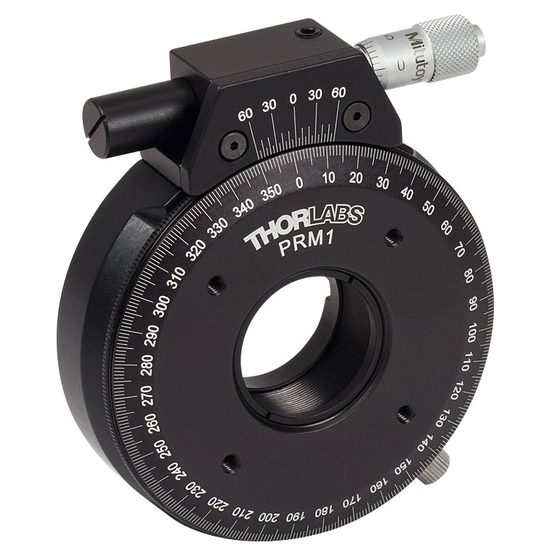 |
| Features | Standard | External SM1 (1.035"-40) Threads |
Adjustable Zero | Two Independently Rotating Carriages | Rotates Optic Within Fixed Lens Tube System |
Continuous 360° Rotation or 15° Increments |
Continuous 360° Rotation or 22.5° Increments |
Micrometer |
| Additional Details | ||||||||
| Rotation Mounts for Ø1" Optics | ||||||
|---|---|---|---|---|---|---|
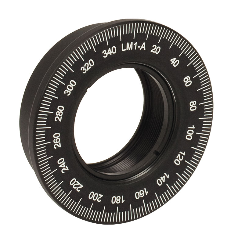
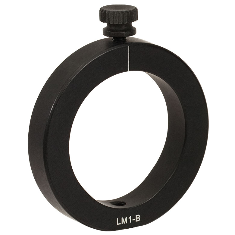
| Item # | LM1-A & LM1-B(/M) |
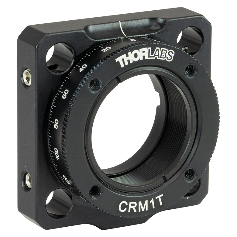
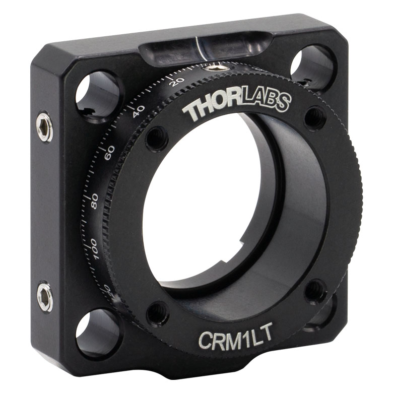
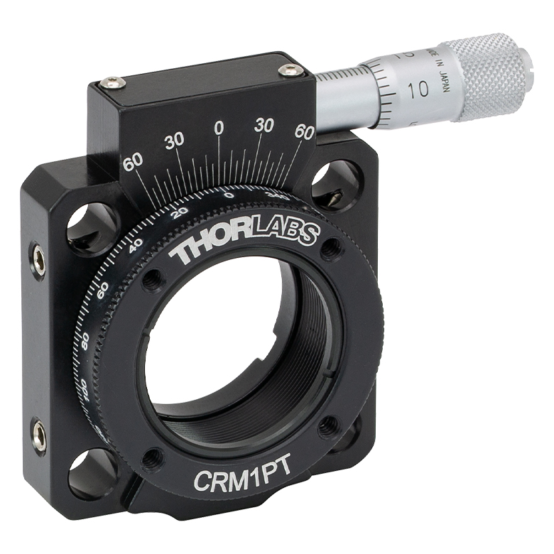
CRM1T(/M) | CRM1LT(/M) | CRM1PT(/M) | KS1RS | K6XS |
| Click Photo to Enlarge |
  |
 |
 |
 |
 |
 |
| Features | Optic Carriage Rotates Within Mounting Ring | 30 mm Cage-Compatiblea | 30 mm Cage-Compatible for Thick Opticsa |
30 mm Cage-Compatible with Micrometera |
±4° Kinematic Tip/Tilt Adjustment Plus Rotation | Six-Axis Kinematic Mounta |
| Additional Details | ||||||
| Rotation Mounts for Ø2" Optics | |||||||
|---|---|---|---|---|---|---|---|
| Item # | RSP2(/M) | RSP2D(/M) | PRM2(/M) | LM2-A & LM2-B(/M) |
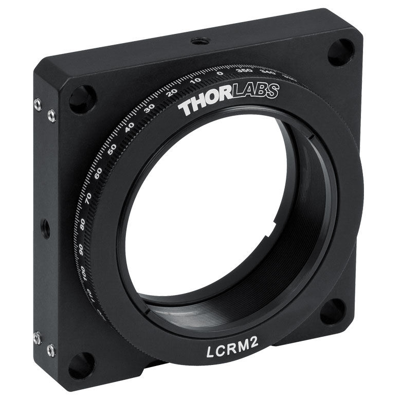
LCRM2(/M) | KS2RS | K6X2 |
| Click Photo to Enlarge |  |
 |
 |
  |
 |
 |
 |
| Features | Standard | Adjustable Zero |
Micrometer | Optic Carriage Rotates Within Mounting Ring | 60 mm Cage-Compatible | ±4° Kinematic Tip/Tilt Adjustment Plus Rotation | Six-Axis Kinematic Mount |
| Additional Details | |||||||
Manual Rotation Stages
| Manual Rotation Stages | ||||||
|---|---|---|---|---|---|---|
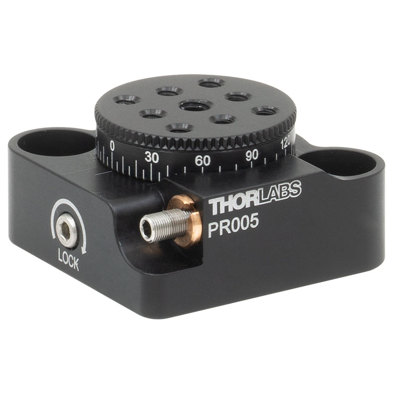
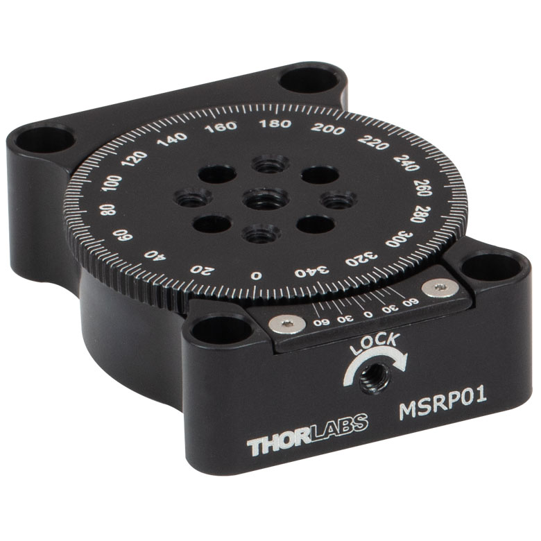
| Item # | RP005(/M) | PR005(/M) | MSRP01(/M) | RP01(/M) | RP03(/M) | QRP02(/M) |
| Click Photo to Enlarge |
 |
 |
 |
 |
 |
 |
| Features | Standard | Two Hard Stops | ||||
| Additional Details | ||||||
| Manual Rotation Stages | ||||||
|---|---|---|---|---|---|---|
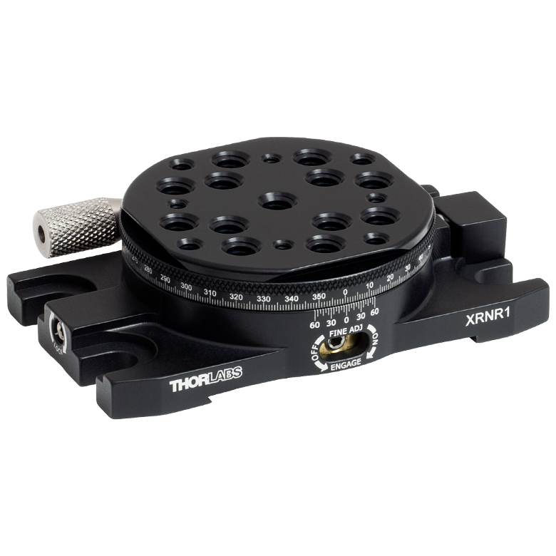
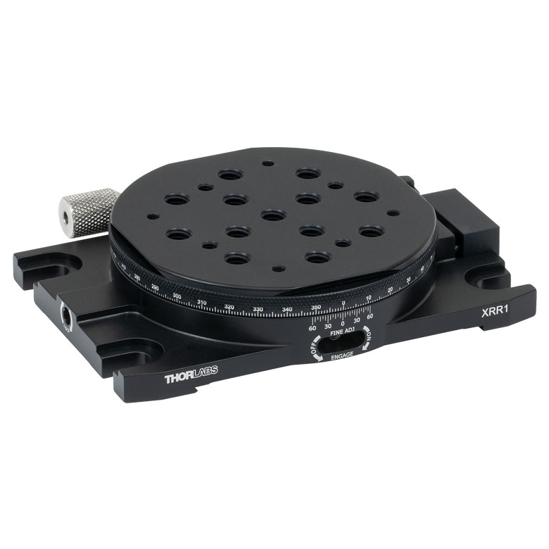
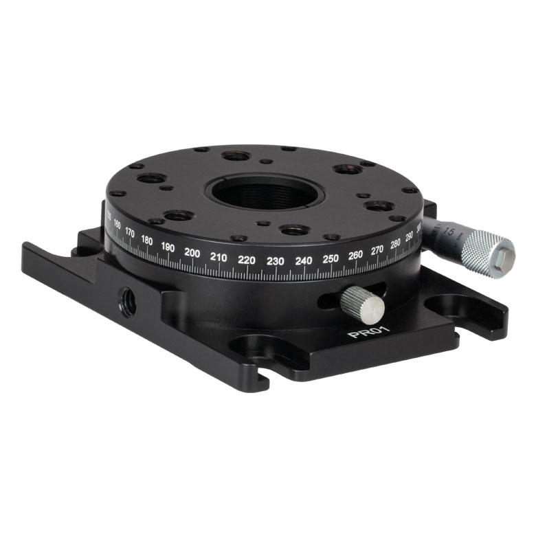
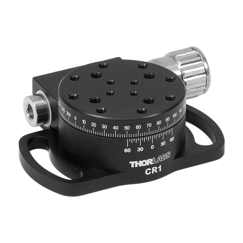
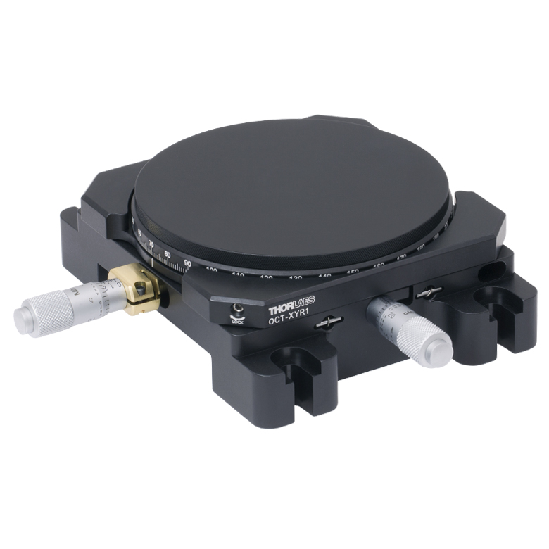
| Item # | XRNR1(/M) | XRR1(/M) | PR01(/M) | CR1(/M) | XYR1(/M) | OCT-XYR1(/M) |
| Click Photo to Enlarge |
 |
 |
 |
 |
 |
 |
| Features | Fine Rotation Adjuster and 2" Wide Dovetail Quick Connect |
Fine Rotation Adjuster and 3" Wide Dovetail Quick Connect |
Fine Rotation Adjuster and SM1-Threaded Central Aperture |
Fine Pitch Worm Gear | Rotation and 1/2" Linear XY Translation | |
| Additional Details | ||||||
Motorized Rotation Mounts and Stages
| Motorized Rotation Mounts and Stages with Central Clear Apertures | |||||
|---|---|---|---|---|---|
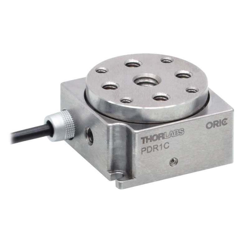
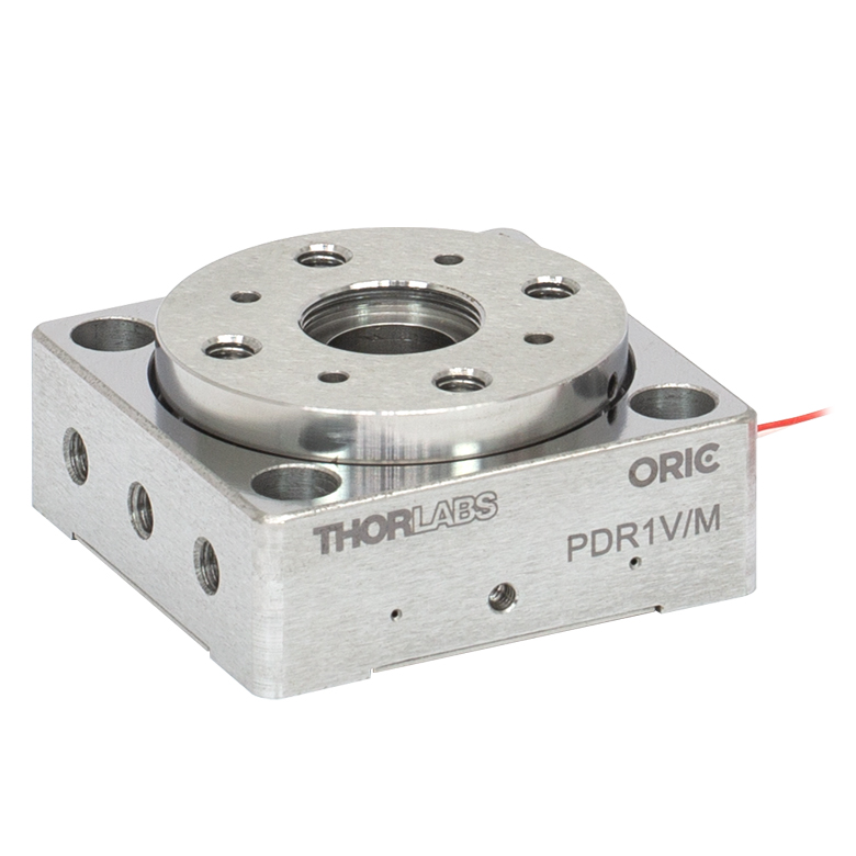
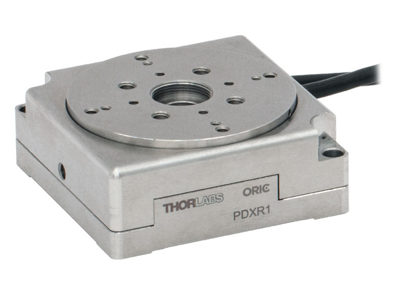
| Item # | DDR25(/M) | PDR1C(/M) | PDR1(/M) | PDR1V(/M) | PDXR1(/M) |
| Click Photo to Enlarge |
 |
 |
 |
 |
 |
| Features | Compatible with SM05 Lens Tubes, 16 mm Cage System, & 30 mm Cage System |
Compatible with 16 mm Cage System |
Compatible with SM05 Lens Tubes & 30 mm Cage System |
Vacuum-Compatible; Also Compatible with SM05 Lens Tubes & 30 mm Cage System |
Compatible with SM05 Lens Tubes & 30 mm Cage System |
| Additional Details | |||||
| Motorized Rotation Mounts and Stages with Central Clear Apertures | |||||
|---|---|---|---|---|---|
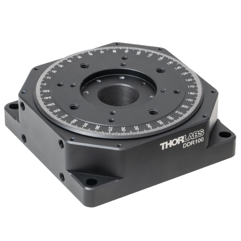
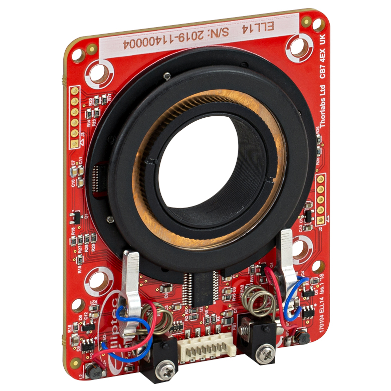
| Item # | K10CR1(/M) | PRM1Z8(/M)a | DDR100(/M) | ELL14 | HDR50(/M) |
| Click Photo to Enlarge |
 |
 |
 |
 |
 |
| Features | Compatible with SM1 Lens Tubes & 30 mm Cage System | Compatible with SM1 Lens Tubes, 16 mm Cage System, 30 mm Cage System |
Compatible with SM1 Lens Tubes, Open Frame Design for OEM Applications |
Compatible with SM2 Lens Tubes |
|
| Additional Details | |||||
| Motorized Rotation Mounts and Stages with Tapped Platforms | ||
|---|---|---|
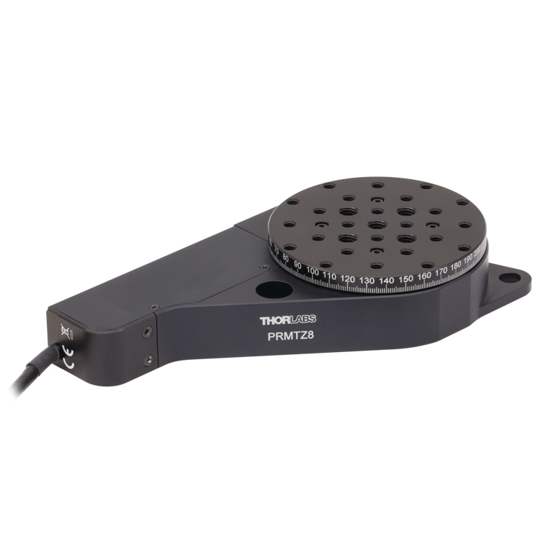
| Item # | PRMTZ8(/M)a | ELL18(/M)b |
| Click Photo to Enlarge |
 |
 |
| Features | Tapped Mounting Platform for Mounting Prisms or Other Optics | Tapped Mounting Platform, Open Frame Design for OEM Applications |
| Additional Details | ||

 Zoom
Zoom
Click to Enlarge
PR01(/M) Schematic
- 360° Rotation Platform
- Micrometer Provides 2.4 arcmin Rotation per Division
- SM1-Threaded Center Hole Accepts Ø1" (Ø25.4 mm) Optics up to 0.67" (17 mm) Thick
- Load Capacity: 25 lb (11.4 kg) for Coarse Adjustment, 3.75 lb (1.7 kg) for Fine Adjustment
- One SM1RR Retaining Ring Included
The PR01(/M) Rotation Stage is a heavy-duty stage designed to precisely rotate optics, standard optomechanical assemblies, and segments of 30 mm cage systems. The rotating platform is engraved with 1° graduations and includes a vernier scale that directly provides 5 arcmin resolution.
It contains 1/4" (M6) counterbored mounting slots, as well as two 1/4"-20 (M6) taps for mounting in the vertical plane. For additional stability in vertical configurations, it can be attached to our CAM1 Right-Angle Bracket.

 Zoom
Zoom
Click for Details
PR01A Mounting Hole Pattern
- Provides Solid Mounting Surface for Prisms, Beamsplitters, Polarizers, and Other Optics
- Tapped Hole Array is Directly Compatible with Mini Translation Stages and Goniometers
- Contains Six Mounting Locations for Clamping Arms
- Four 4-40 Cap Screws Included
The PR01A(/M) Adapter Plate fastens to the top of the PR01(/M) Rotation Stage via four #4 counterbored holes. The imperial version contains twelve 2-56 taps, positioned to provide direct mechanical compatibility with our miniature translation stages and goniometers, while the metric version contains four 2-56 taps and eight M2 x 0.4 taps that serve the same function.
Alternatively, optics can be fixed on top of the adapter plate with our PM3(/M) or PM4(/M) Clamping Arms and rotated about the PR01's axis of rotation, as shown in the image at the top of the page. Six 6-32 (M4) taps are provided along the outer perimeter for the clamping arms. Four 8-32 (M4) taps are also included, which can be used with the PM5(/M) stainless steel clamping arm.

 Zoom
Zoom
Click for Details
Mechanical Drawings
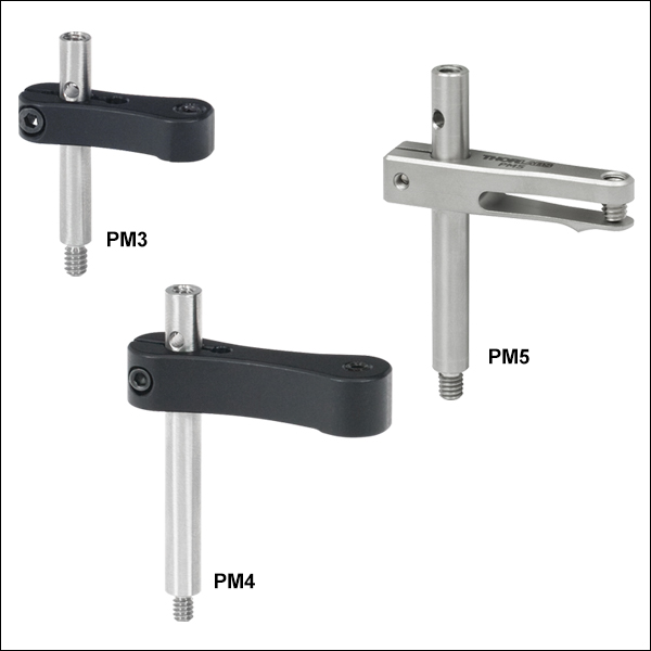
- Provide Clamping Force for Our Platform Mounts
- Threaded Hole on Top and Threaded Stud on Bottom of Post
- 6-32 Threads on PM3 and PM4
- 8-32 Threads on PM5
- M4 x 0.7 Threads on All Metric Versions
- Maximum Optic Heights from 0.97" to 1.65" (24.6 mm to 41.8 mm)
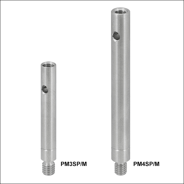
- Extension Posts Available to Increase Max Optic Height
- PM3SP(/M) with PM3(/M): Hold Optics up to 2.21" (56.1 mm) Tall
- PM4SP(/M) with PM4(/M): Hold Optics up to 3.61" (91.7 mm) Tall
Click to Enlarge
Clamping Arm Extension Posts with Metric Indicator Groove
Thorlabs' Clamping Arms provide clamping force to secure optics to our kinematic platform mounts, stages, and V-clamps. The PM3(/M) accommodates optics up to 0.97" tall and features a 0.69" center-to-center distance between the post and the nylon-tipped setscrew that holds the optic. The PM4(/M) accommodates optics up to 1.61" and features a 1.16" center-to-center distance between the post and the nylon-tipped setscrew. The maximum optic height of the PM3(/M) or PM4(/M) Clamping Arms can be extended using our PM3SP(/M) or PM4SP(/M) Extension Posts, respectively. These extension posts are identical to the posts included in each complete clamping arm. Each clamping arm features 6-32 (M4 x 0.7) threads. The PM3 and PM4 can be mounted in 8-32 tapped holes by using the AS6E8E thread adapter, which features internal 6-32 threads and external 8-32 threads. This thread adapter has an outer diameter of 0.24", which is the same as the PM4SP extension post and the post included with the PM4 clamping arm. This allows the clamping arm to be adjusted across the seam between either post and the adapter. The smaller diameters of the included post for the PM3 clamping arm and the PM3SP extension post cause the thread adapter to act as a stop for the clamping arm.
The PM5(/M) clamping arm is made entirely from heat-treated stainless steel, which helps maintain stability in fluctuating temperatures and provides vacuum compatibility. This clamping arm is recommended for use with the POLARIS-K1M4(/M), but it can be used with any platform mount or stage that has one or more 8-32 (M4 x 0.7) tapped holes. The PM5(/M) can hold optics up to 1.65" tall, and the distance from the post center to the contact point that holds the optic is 0.90".
Each clamping arm is attached to its post using a flexure mechanism that locks with a 5/64" (2.0 mm) balldriver or hex key. The setscrew on top of the clamping arm also accepts a 5/64" (2.0 mm) balldriver or hex key in order to clamp down on the optic. The post includes a through hole which can be leveraged for added torque when tightening down the post. Please see the diagram above for additional information.

 Zoom
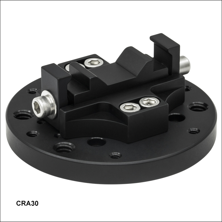
Zoom- Continuously Rotate a 30 mm Cage Segment through 360°
- Accepts Preassembled 30 mm Cage System Segments; No Disassembly is Required
- Single-Screw Clamping Mechanism
- Four 4-40 Cap Screws Included
The CRA30 Cage Rotation Adapter connects a 30 mm cage segment to a PR01(/M) Rotation Stage, allowing the cage segment to be precisely aligned via the stage's micrometer. The adapter uses a single-screw clamping mechanism that simultaneously tightens around two cage rods in a 30 mm cage system. Preassembled cage segments can simply be dropped into the open clamp; it is not necessary to feed the cage rods through the adapter.