 Products Home / Optomechanical Components / Optical Post Assemblies / Bases / Table Clamps / Post Bases
Post Bases
- Rigid One-Piece Construction for Superior Stability
- Convert Our Ø1" and Ø1.5" Posts into "Pedestal Style" Mounts
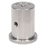
BE1/M
Adapter with M6
Stud for Ø25.0 mm Posts
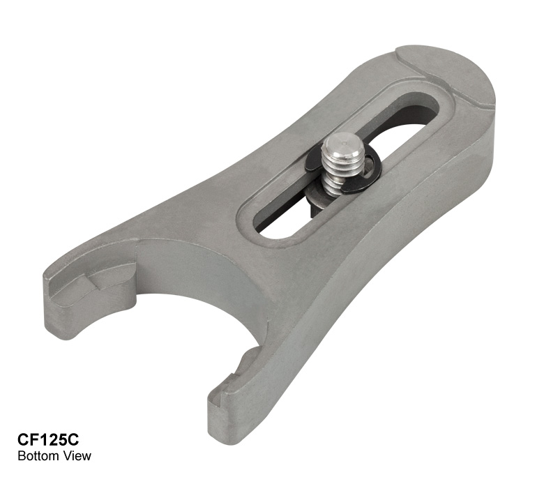
CF125
Shown with
PH2 Post Holder
PB1
1/4" (M6) Counterbores
(4 Top, 1 Bottom)
PB2
1/4" (M6) Counterbored Slots
1/4"-20 Center Tap
(M6 Center Tap in PB2/M)
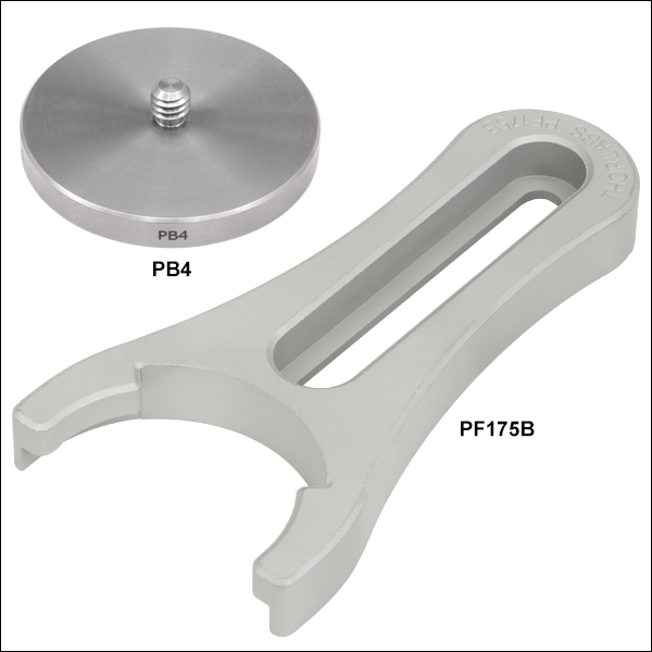
PB4
Adapter with 1/4"-20
Stud for Ø1.5" Posts
PF175B
Shown with a Ø1.5" Pedestal Post


Please Wait
Click to Enlarge
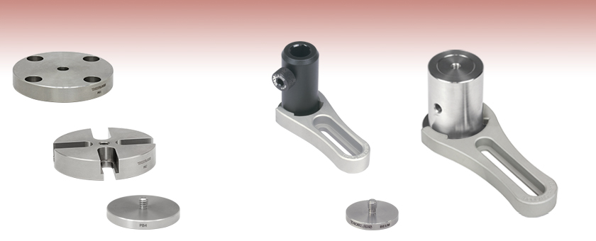
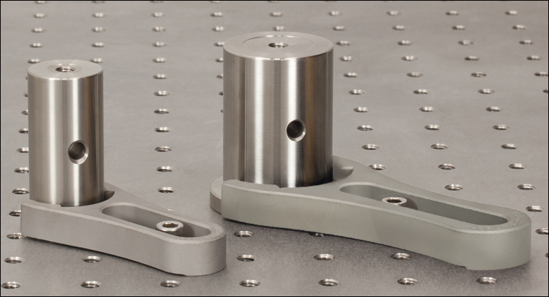
Ø1" and Ø1.5" Posts can be Secured to an Optical Table Using Post Base Adapters and Clamping Forks
Features
- Convert Ø1" Post Extensions and Ø1.5" Posts into Pedestal-Style Posts
- All Bases Provide Large Bottom Relief Cuts for Exceptional Stability
- Clamping Forks Offer Exceptional Positional Mounting Flexibility
Ø1" Post Bases
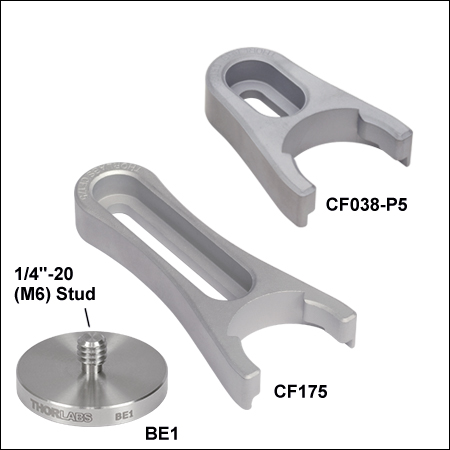
The BE1(/M) and BE1R(/M) fasten directly to a Ø1" post extension or a Ø1/2" post holder via the provided 1/4"-20 (M6) stud, converting a standard post or post holder into a pedestal-style mount. For additional stability in temporary setups, the BE1R(/M) base provides a high-strength magnet in the base. Ø1" pedestal configurations are directly compatible with our CF038-P5, CF038C(/M)-P5, CF125, CF125C(/M), CF175, and CF175C(/M) solid stainless steel clamping forks, which provide for the greatest overall positional flexibility when mounting to an optical table.
Ø1.5" Post Bases
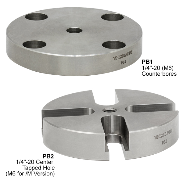
The PB1 and PB2(/M) fasten directly to a Ø1.5" post via 1/4"-20 (M6) cap screws placed through the bottom-located counterbores in the base. The PB1 offers four top-located 1/4" (M6) counterbores located on 1" centers for compatibility with both imperial and metric optical tables and breadboards. The PB2 provides four 1/4" (M6) counterbored slots for additional positional freedom where alignment on an optical table does not conform to standard table mounting hole spacing.
The PB4(/M) and PB4R(/M) provide even greater positional flexibility by fastening directly to a Ø1.5" post via the provided 1/4"-20 (M6) stud, converting a standard post into a pedestal-style post. The PB4R(/M) adapter has four high strength magnets in the base for additional stability. These pedestal configurations are directly compatible with the PF85B, PF125B, or PF175B clamping fork, which provides high positional flexibility when mounting to an optical table.

Insights into Best Lab Practices
Scroll down to read about a few things we consider when setting up lab equipment.
- Clamping Forks: Tip for Maximizing the Holding Force
- Optical Tables: Clamping Forks and Distortion of the Table's Surface
Click here for more insights into lab practices we follow.
Clamping Forks: Tip for Maximizing the Holding Force
Click to Enlarge
Figure 2: More than half the total applied force (FTotal) holds the object, since L1 > L2. The height of the left leg of this CL2 clamp is variable to compensate for the object's height. This allows the clamp's top surface and the mounting surface to be made parallel.**
Click to Enlarge
Figure 1: Less than half the total applied force (FTotal) holds the object, since L1 < L2. The clamp illustrated above is the CL5A.
Clamped objects can be fairly easy to move when the torqued screw in the clamp's slot is positioned too far from the object. Correct positioning of the screw protects clamped objects from being knocked out of position.
To maximize the clamping force, position the screw as close as possible to the object.**
This works since clamps like CL5A and CL2 (Figures 1 and 2, respectively) divide the torqued screw's applied force (FTotal) between two points.
Clamping force F2 is applied to the object. The value of F2 is a percentage of FTotal and depends on L1 and L2, as described below. The remainder (F1) of the total force is applied through the opposite end of the clamp.
The following equations can be used to calculate the two applied forces.
Object: |
 |
|
| Force Applied to Other Contact Point: |
 |
These equations show that the clamping force on the object increases as the distance between the object and screw decreases. The force supplied by the torqued screw is evenly divided between F1 and F2 when L1 and L2 are equal.
**Note that maximizing the clamping force also requires both the top surface of the clamp and the area it contacts on the object to be parallel with the mounting surface, as depicted in Figures 1 and 2.
If the tangent at the interface between the clamp and object is not parallel to the mounting surface, the force applied to the object will be divided between pressing it into and pushing it across the mounting surface. The force directed along the mounting surface may, or may not, be sufficient to translate the object.
To accommodate different object heights, clamps like the CL2 have one threaded, variable-length leg, which is shown on the left in Figure 2. The number of threads between the clamp and mounting surface should be adjusted to compensate for the height of the object and to keep the clamp's top surface level with the table.
Date of Last Edit: Dec. 4, 2019
Optical Tables: Clamping Forks and Distortion of the Table's Surface
Click to Enlarge
Figure 3: The construction of a Nexus table / breadboard includes a (1) top skin, (2) bottom skin, (3) side finishing trim, (4) side panels, and (5) honeycomb core. The stainless steel top and bottom skins are 5 mm thick.
Clamping forks are more rigid than the mounting surface of composite optical tables. It might be expected that the spine of the clamping fork would bend with the force exerted by the screw as the torque is increased. Instead, the screw will pull the skin of the table up and out of flat before the clamping fork deforms. Due to this, clamping forks should be used with care when securing components to optical tables. Clamping arms, which are discussed in the following, are alternatives to clamping forks that are less likely to deform the table's mounting surface.
Optical Table Construction
Optical tables and breadboards with composite construction (Figure 3) are designed to be rigid while providing vibration damping. The 5 mm thick, stainless steel top skin is manufactured to be flat, but a localized force can deform it. When the top skin is deformed, optical components will not sit flat, and optical system alignment and performance can be negatively affected.
Clamping Forks
Standard clamping forks are installed with one edge placed on the table's surface and the opposite edge on the object (Figure 4). Between these two edges, there is clearance between the bottom of the clamp and the surface of the table. This bridge makes it possible to use a single screw to both secure the clamp to the table and exert a holding force on the object.
When the clamp is secured by torqueing the screw, the screw pulls up on the top skin of the table (Figure 5).
As the torque on the screw increases, the top skin of the table rises. Not only does pulling up on the table surface risk permanently damaging the table, this can also disturb the alignment of the optical component the clamp is being used to secure. By lifting the table's skin, the mounting surface under the clamped object tilts.
Click to Enlarge
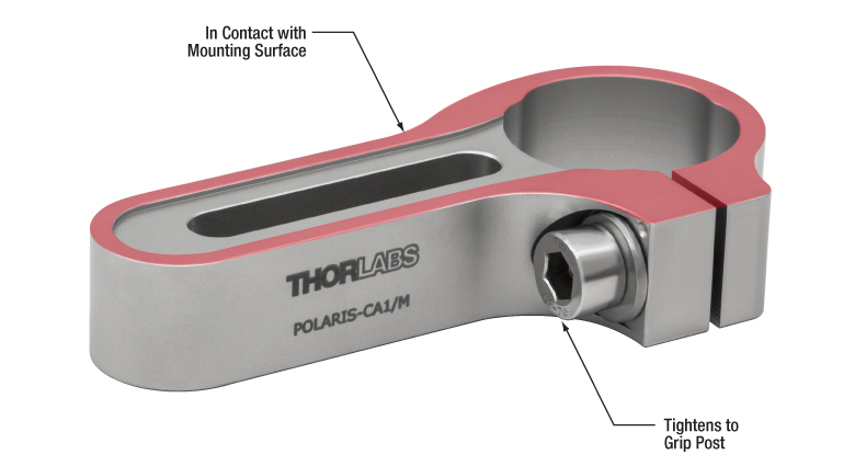
Figure 6: The POLARIS-CA1/M clamping arm has a slot that accepts a mounting screw, a separate screw that applies a clamping force to an installed post, and identical top and bottom surfaces. Since a nearly continuous track around the surface of the clamping arm is in contact with the mounting surface, clamping arms cause negligible bridging effects.
Click to Enlarge
Figure 5: Torqueing the screw creates a force that pulls up on the table's top skin. The lifted skin tilts the mounting surface and can induce angular deviation of the object. This effect is exaggerated in the above image for illustrative purposes.
Click to Enlarge
Figure 4: A standard clamping fork, such as the CL5A, contacts the table along only one edge. The opposite edge is in contact with the object to be secured. A bridge forms between the two. The screw that applies the clamping force is not shown.
Clamping Arms
Clamping arms, such as the POLARIS-CA1/M, shown in Figure 6, are designed to secure a post while minimally deforming the mounting surface.
The clamping arm in Figure 6 differs from clamping forks in two significant ways. One is the surface area that makes contact with the optical table, which is highlighted in red, and the other is the method used to secure the post.
The area in contact with the optical table makes a nearly continuous loop around the base of the clamp. The contact area is flat and flush with the table when the clamp is installed. The only break in the loop is a narrow slot in the vise used to grip the post.
This design uses two screws, instead of the clamping fork's single screw. One screw (not shown) secures the clamp to the table, and the other (indicated) is tightened to grip the post. Since one screw is not required to perform both tasks, it is not necessary for this clamping arm to form a bridge between the clamped object and the optical table.
Although the contact area is a loop, and not a solid surface, this clamp causes negligible distortion of the mounting surface. This is due to the open area inside the contact surface being narrow and surrounded by the sides of the clamp, which resist the force pulling up on the table.
Date of Last Edit: Dec. 4, 2019
| Posted Comments: | |
ITANDEHUI GRIS SANCHEZ
(posted 2024-02-12 14:22:34.28) Regarding the PB1post base, is there a metric option? In the items description it says there is a metric option but when looking into the schematics dimensions it does not seem compatible. The other option could be PB2 but our preference is PB1. Could you clarify? jdelia
(posted 2024-02-12 03:05:32.0) Thank you for contacting Thorlabs. The four counterbored holes on the PB1 are provided at the proper spacing for compatibility with an imperial or metric optical table or optical breadboard, so we do not offer separate imperial and metric version. ludoangot
(posted 2016-11-11 16:01:40.59) Hello, I have a suggestion: a counterbored version of your magnetic pedestal base (BE1R) so that it could be used for both M6 and 1/4"-20 by the user providing the appropriate screw. tfrisch
(posted 2016-11-14 09:06:59.0) Hello, thank you for this suggestion. I have posted it in our internal engineering forum. Thorlabs
(posted 2010-09-08 21:33:45.0) Response from Javier at Thorlabs to last poster: Thank you very much for pointing this typo out. The correct threads are 1/4"-20 (M6). We have corrected the information on the webpage. user
(posted 2010-09-08 14:10:00.0) [misprint?]
Overview>Ø1" Post Bases
The BE1 fastens directly to a Ø1" RS-Series Post via the provided ?#8-32 (M4)? stud,
====> M4? or M6? |

 Zoom
Zoom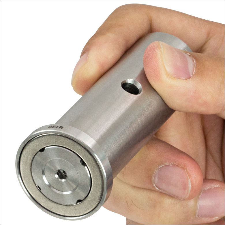
Click to Enlarge
The BE1R has a magnet in the base for stability in temporary setups.
 Click to Enlarge
These base adapters feature a 1/8" (3 mm) hex socket on the bottom for tightening.
Click to Enlarge
Several Slot Lengths Available
- BE1(/M) and BE1R(/M) Adapters Convert Standard Ø1/2" Post Holders and Ø1" Posts into Pedestal-Style Mounts
- Clamping Fork or CL8 Table Clamp Secures Pedestal-Style Mount to a Breadboard or Optical Table
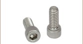
- Three Sizes Provide Clamping with 1/4"-20 (M6) Cap Screws
- 0.40" (10.2 mm) Long Counterbored Slot [CF038-P5 and CF038C(/M)-P5]
- 1.24" (31.5 mm) Long Counterbored Slot [CF125 and CF125C(/M)]
- 1.75" (44.4 mm) Long Counterbored Slot [CF175 and CF175C(/M)]
- Swivel Clamping Fork 360° to Select Most Convenient Mounting Hole
- CF038C(/M)-P5, CF125C(/M) and CF175C(/M) Each Include a 1/4"-20 (M6)-Threaded Captive Screw
- BE1(/M) and All Clamping Forks Available in Packs of Five [CF038-P5 and CF038C(/M)-P5 Not Sold Individually]
Pedestal Base Adapters
The BE1(/M) and BE1R(/M) pedestal base adapters feature a 1/4"-20 (M6)-threaded stud that fit into the bottom of our standard Ø1/2" post holders or Ø1" posts to convert them into pedestal-style mounts for added stability. The BE1R(/M) adapter features a magnet in the base that is sufficiently strong to securely hold the base in place without clamping to an optical table (see photo at the top right). Made from solid 303 stainless steel with a 1.25" (31.8 mm) outer diameter, these adapters allow standard Ø1" posts to be used with the clamping forks sold below.
The BE1(/M) base adapter is available in a pack of five for ease of ordering.
Clamping Forks
These clamping forks are designed to provide exceptional clamping force when used with our Ø1/2" post holders and Ø1" posts that have been adapted using the BE1(/M) or BE1R(/M) to pedestal-style mounts. They can also be used with our pedestal-style Ø1/2" post holders or Ø1" pedestal posts without any need for the BE1(/M) or BE1R(/M).
Fabricated from solid 303 stainless steel, all of these clamping forks create three points of contact with the table for high stability. For flexibility in the positioning of post assemblies, the CF038-P5 and CF038C(/M)-P5 forks offer 0.40" (10.2 mm) long counterbored slots, the CF125 and CF125C(/M) forks offer 1.24" (31.5 mm) long counterbored slots, and the CF175 and CF175C(/M) forks have 1.75" (44.4 mm) long counterbored slots. The counterbored slots on the CF038-P5, CF125, and CF175 forks are designed for user-supplied 1/4"-20 (M6)-threaded cap screws. For further convenience, the CF038C(/M)-P5, CF125C(/M), and CF175C(/M) forks each include a 1/4"-20 (M6)-threaded captive screw. Please note that significant over tightening of clamping forks can deform the surface of an optical table, which can cause misalignment of components and decrease stability.
Our clamping forks are also available in packages of five for ease of ordering (note: the CF038-P5 and CF038C(/M)-P5 clamping forks are only available in packs of five).

 Zoom
ZoomPB1
This universal post base has a 1/4" (M6) counterbored hole in the center that allows the base to be attached to a Ø1.5" mounting post using a 1/4"-20 (M6) cap screw. Four 1/4" (M6) counterbored holes are provided at the proper spacing for compatibility with an imperial or metric optical table or optical breadboard. The base contains a mounting hole for 1" or 25 mm centers.
PB2 and PB2/M
These post bases have counterbored slots that allow for additional freedom in the placement of Ø1.5" mounting posts. The PB2 has a center-tapped 1/4"-20 hole while the PB2/M has a center-tapped M6 hole. The PB2/M has an identifying ring engraved around the tapped hole on the bottom face of the base. Use a 1/4"-20 (M6) setscrew to attach the PB2 (PB2/M) base to a Ø1.5" mounting post.
Pedestal Base Adapter
The PB4(/M) and PB4R(/M) pedestal base adapters feature 1/4"-20 (M6)-threaded studs, which fit into the bottom of our Ø1.5" posts to convert them into pedestal-style mounts. The PB4(/M) can be tightened onto the post or postholder using a 1/8" (3 mm) hex key or ball driver, while the PB4R(/M) has a 3/16" (5 mm) hex socket. The PB4R(/M) also has four high strength magnets in the base that are sufficiently strong to securely hold the base in place without clamping to an optical table. The adapters are made from solid 303 stainless steel with a 1.85" (47.0 mm) outer diameter. They can be secured to a breadboard using the PF85B, PF125B, or PF175B clamping fork or CL8 clamp (sold separately below).

 Zoom
Zoom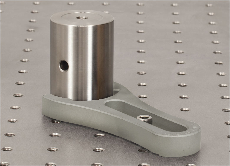
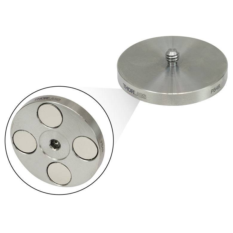
Click to Enlarge
The PB4R(/M) has a 3/16" (5 mm) hex socket and four magnets in the base.
- PB4(/M) and PB4R(/M) Adapters Convert Ø1.5" Posts to Pedestal-Style Mounts
- Clamping Forks Secure Pedestal-Style Mount to a Breadboard or Optical Table
- Three Counterbored Slot Options:
- 0.85" (21.6 mm), 1.25" (31.8 mm), or 2.12" (53.8 mm)
- Swivel Fork 360° to Select Most Convenient Mounting Hole
- Available Individually or in Packs of 5
- Three Counterbored Slot Options:
Pedestal Base Adapters
The PB4(/M) and PB4R(/M) pedestal base adapters feature a 1/4"-20 (M6)-threaded stud, which fits into the bottom of our Ø1.5" posts to convert them into pedestal-style mounts. Made from solid 303 stainless steel with a 1.85" (47.0 mm) outer diameter, these adapters allow these posts to be used with our clamping forks. The PB4(/M) can be tightened onto the post or postholder using a 1/8" (3 mm) hex key or ball driver, while the PB4R(/M) has a 3/16" (5 mm) hex socket as well as four high strength magnets in the base that are sufficiently strong to securely hold the base in place without clamping to an optical table.
Clamping Forks
The PF85B, PF125B, and PF175B clamping forks are designed to provide exceptional clamping force when used with our Ø1.5" posts that have been adapted using the PB4(/M) or PB4R(/M) pedestal bases. These clamping forks can also be used with our Ø1" post holders or BLP01 adjustable-height post without any need for the PB4(/M) or PB4R(/M) bases.
Made from stainless steel, these clamping forks create three points of contact with the table for high stability. The counterbored slots for 1/4"-20 (M6) cap screws allow the most convenient mounting hole to be selected. For flexibility in the positioning of post assemblies, Thorlabs offers three sizes: the PF85B fork has a 0.85" (21.6 mm) long counterbored slot, the PF125B fork has a 1.25" (31.8 mm) long counterbored slot, and the PF175B fork has a 2.12" (53.8 mm) long counterbored slot. Please note that significant overtightening of clamping forks can deform the surface of an optical table, which can cause misalignment of components and decrease stability.
These clamping forks are available idividually or in packs of five.

 Zoom
Zoom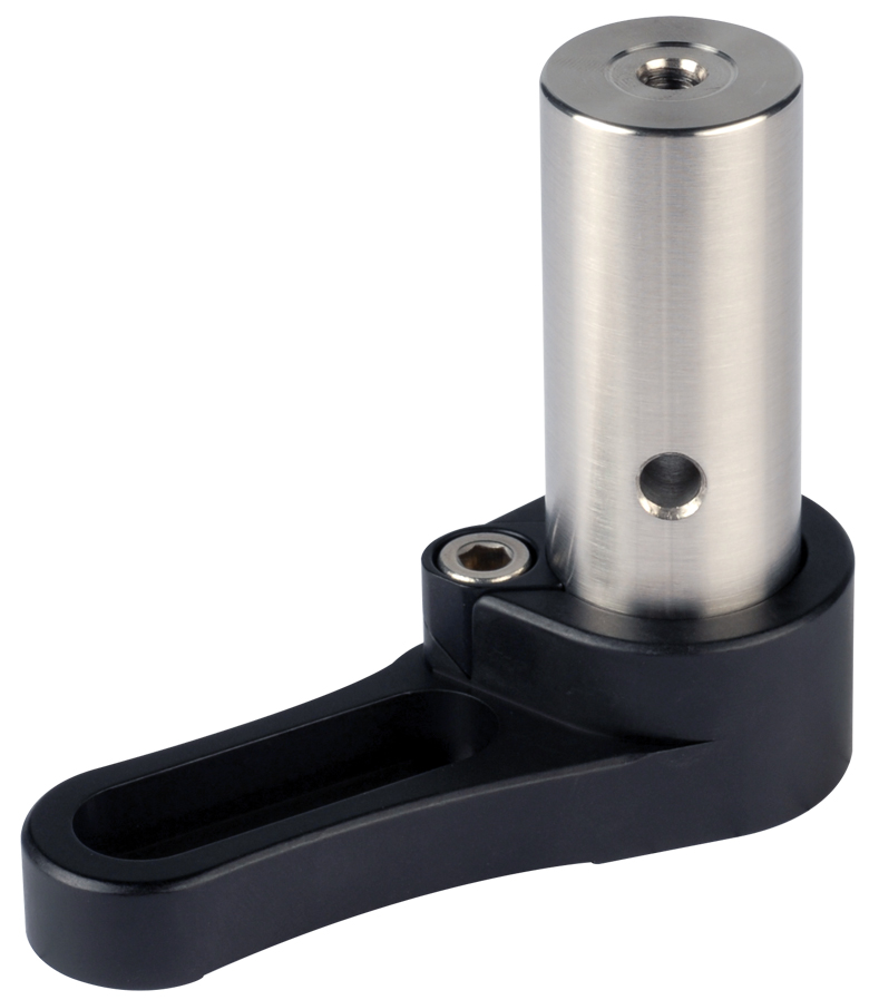
Click to Enlarge
Deep Base Allows Height Adjustment
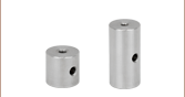
- RB2 Base Allows Post Extensions to be Used as a Variable Height Mounting Structure
- Hollow Base Allows Post Extension to Pass Through for 0.5" of Height Adjustability
- Convenient Vertically Accessed Locking Screw
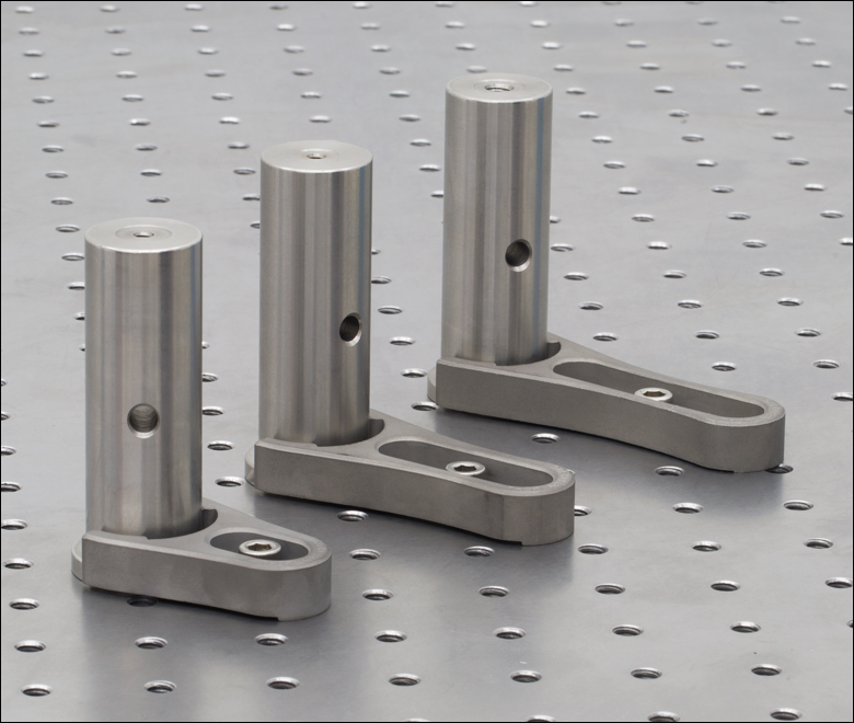
The RB2(/M) pillar post base mounts Ø1" (25 mm) optical posts at a variable height (shown to the right). The hollow base allows the post to pass through, allowing 0.5" of post height adjustment. Translation is locked via a top-located clamping screw.

 Zoom
Zoom- Mark the Position of Ø1" and Ø1.5" Posts within an Optical System
- Realignment Based on Two Contact Points
- Third Contact Point for Realigning Square Components
- Swivel Head Retainer Available with 200° of Rotation
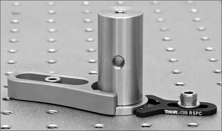
Thorlabs' Position Retainers can be used to realign posts that have been removed from an optical system. They act as markers on the breadboard or optical table in the event that you need to remove a post from your setup. The two dots near the ends of the outer arms of the retainer mark the two points of post contact. The third dot, located within the V-groove, is for retaining the position of a square base or other squared-off component. For more information on using our retainers with square components, click here.
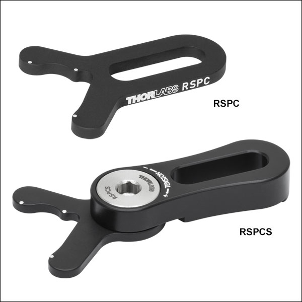
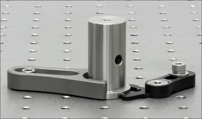
The RSPC Fixed Retainer is a compact solution for use with Ø1" and Ø1.5" Pedestal Posts. The post should be independently clamped down before aligning the RSPC retainer. After the retainer is mounted in place, the post can be removed from the setup and then later placed back into the same position.
The RSPCS(/M) Swivel Retainer features a swivel head for 200° of rotational adjustment. This allows for access to additional mounting holes on the breadboard. The post should be independently locked before aligning RSPCS(/M) retainer. Partially loosen the tension adjuster screw and then mount the retainer to a breadboard tap while maintaining contact with the post. Lastly, tighten the tension adjuster screw. After this the component can be removed from the setup and then later placed back into the same position.
Click to Enlarge RSPCS Swiveling Position Retainer