 Products Home / Optomechanical Components / Optomechanical Mounts / Translation Optic Mounts / Translating Rectangular Optic Holders
Translating Rectangular Optic Holders
- Mount Rectangular Optics, Test Targets, or Beam Targets up to 4 mm Thick
- One- or Two-Axis Translation
- 8-32 (M4) Tapped Holes Provide Several Mounting Options
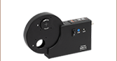
XYF2
XY Translation Mount
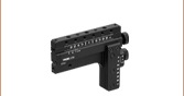
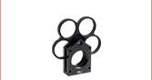
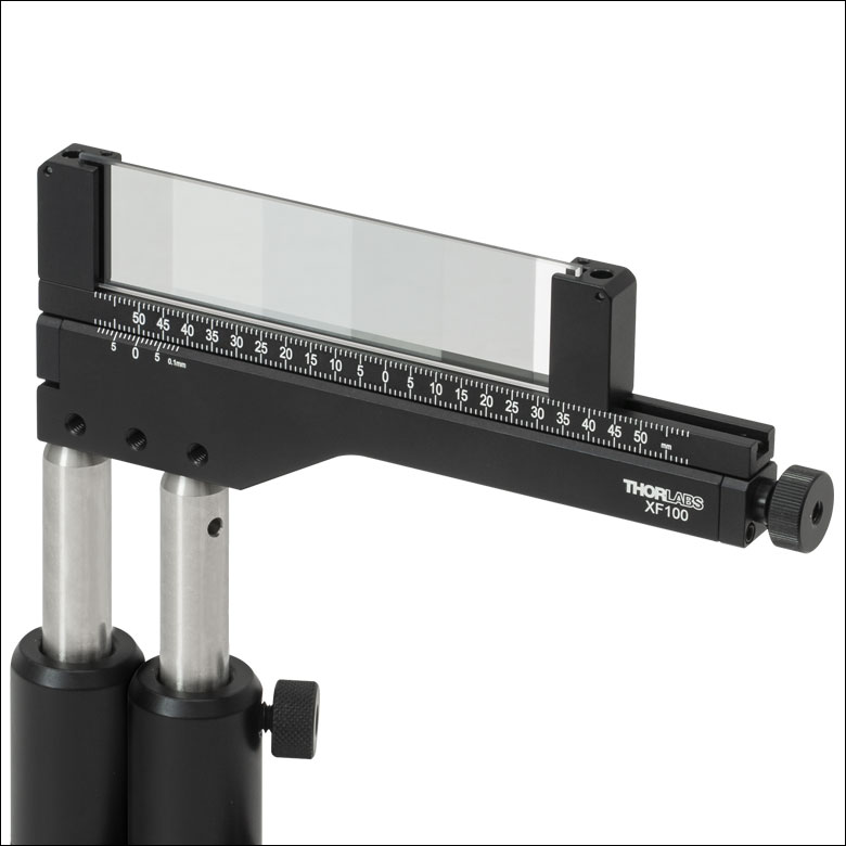
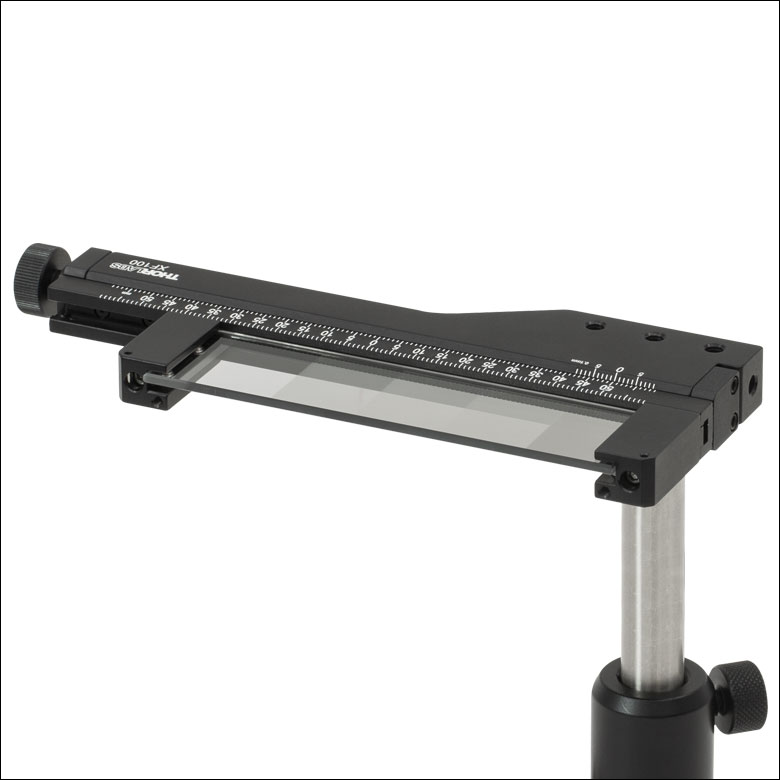
XF100
One-Axis 100 mm Translation Mount
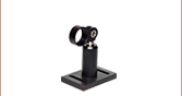
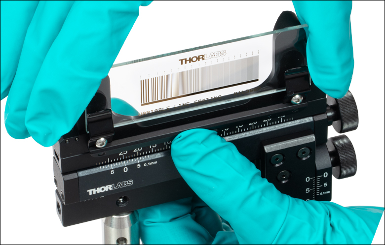
Application Idea
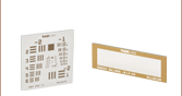
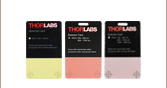
Vertically Mounted XYF1 Translating Filter Mount Holding an R1L3S6P Test Target


Please Wait
| Filter Mount Selection Guide |
|---|
| Fixed Rectangular Optic Mounts |
| Translating Rectangular Optic Mounts |
| Fast-Change Lens-Tube Filter Holder |
| Cage-Compatible Filter Mounts |
| Filter Mount with Sliding Inserts |
| Manual Flip Mounts |
| Motorized Flip Mounts |
| Piezo-Driven Multi-Position Sliders |
| In-Line MM Fiber Optic Filter Mounts |
| Complete Filter Mount Selection |
Features
- Translating Filter Mounts Securely Hold a Variety of Plate Optics
- Support Filter Thicknesses up to 0.16" (4 mm)
- One- or Two-Axis Translation Options Available
- Vernier Scale Provides 100 μm Resolution
- XF50(/M), XF100(/M), and XYF1(/M) Mounts use Nylon-Tipped Setscrews to Secure Optics
- XYF2(/M) Mount uses a Set of Spring Clips to Secure Optics
Thorlabs offers Translation Mounts with options for mounting rectangular optics from 12.7 mm (0.50") to 126.2 mm (4.97") wide and up to 4 mm (0.16") thick. The XF50(/M) and XF100(/M) mounts offer 50 mm (1.97") and 100 mm (3.94") translation along a single axis, respectively, while the XYF1(/M) and XYF2(/M) mounts provide translation over a 50 mm x 30 mm (1.97" x 1.18") area. The vernier scale allows for repeatable positioning of the optic with a resolution of 100 μm; please see the Vernier Scales tab for more information. 8-32 (M4) tapped holes on the mounts provide several post-mountable orientations, and nylon-tipped setscrews secure the optic while preventing any damage to the optic surface.
Alternatively, Thorlabs' XYA1(/M) translation adapter provides the same 50 mm x 30 mm translation range as the XYF1(/M) and XYF2(/M) mounts below, but features counterbores and threaded holes for mounting fixed optic mounts, such as fixed filter holders.
Click to Enlarge
Figure 1: An example of how to read a vernier scale. The red arrow indicates what is known as the pointer. Since the tick mark labeled 10 on the vernier scale aligns with one of the tick marks on the main scale, this vernier scale is reading 75.60 (in whatever units the tool measures).
Reading a Vernier Scale
Vernier scales are typically used to add precision to standard, evenly divided scales (such as the scale on Thorlabs' rotation mounts). A vernier scale has found common use in many precision measurement tools, the most common being calipers and micrometers. The direct vernier scale uses two scales side-by-side: the main scale and the vernier scale. The vernier scale has a slightly smaller spacing between its tick marks (10% smaller than the main). Hence, the lines on the main scale will not line up with all the lines on the vernier scale. Only one line from the vernier scale will match well with one line of the main scale, and that is the trick to reading a vernier scale.
Figures 1 through 3 show a vernier scale system for three different situations. In each case, the scale on the left is the main scale, while the small scale on the right is the vernier scale. When reading a vernier scale, the main scale is used for the gross number, and the vernier scale gives the precision value. In this manner, a standard ruler or micrometer can become a precision tool.
The 0 on the vernier scale is the "pointer" (marked by a red arrow in Figs. 1 - 3) and will indicate the main scale reading. In Figure 1 we see the pointer is lined up directly with the 75.6 line. Notice that the only other vernier scale tick mark that lines up well with the main scale is 10. Since the vernier 0 lines up with the main scale’s 75.6, the reading from Figure 1 is 75.60 (in whatever units the tool measures in).
That is essentially all there is to reading a vernier scale. It's a very straightforward way of increasing the precision of a measurement tool. To expound, let’s look at Figure 2. Here we see that the pointer is no longer aligned with a scale line, instead it is slightly above 75.6, but below 75.7; thus the gross measurement is 75.6. The first vernier line that coincides with a main scale line is the 5, shown with a blue arrow. The vernier scale gives the final digit of precision; since the 5 is aligned to the main scale, the precision measurement for Figure 2 is 75.65.
Since the vernier scale is 10% smaller than the main scale, moving 1/10 of the main scale will align the next vernier marking. This asks the obvious question: what if the measurement is within the 1/10 precision of the vernier scale? Figure 3 shows just this. Again, the pointer line is in between 75.6 and 75.7, yielding the gross measurement of 75.6. If we look closely, we see that the vernier 7 (marked with a blue arrow) is very closely aligned to the main scale, giving a precision measurement of 75.67. However, the vernier 7 is very slightly above the main scale mark, and we can see that the vernier 8 (directly above 7) is slightly below its corresponding main scale mark. Hence, the scale on Figure 3 could be read as 75.673 ± 0.002. A reading error of about 0.002 would be appropriate for this tool.
As we've seen here, vernier scales add precision to a standard scale measurement. While it takes a bit of getting used to, with a little practice, reading these scales is fairly straightforward. All vernier scales, direct or retrograde, are read in the same fashion.
Click to Enlarge
Figure 2: An Example of a vernier scale. The red arrow indicates the pointer and the blue arrow indicates the vernier line that matches the main scale. This scale reads 75.65.
Click to Enlarge
Figure 3: An Example of a vernier scale. The red arrow indicates the pointer and the blue arrow indicates the vernier line that matches the main scale. This scale reads 75.67, but can be accurately read as 75.673 ± 0.002.
| Posted Comments: | |
| No Comments Posted |

 Zoom
Zoom
Click to Enlarge
A channel allows for translation of the lockable support arms for accommodating optics with different widths.
- Two Sizes Available:
- XF50(/M) Mounts Optics from 12.7 mm (0.50") to 76.2 mm (3.00") Wide
- XF100(/M) Mounts Optics from 12.7 mm (0.50") to 126.2 mm (4.97") Wide
- Maximum Optic Thickness of 4.0 mm (0.16")
- 50 mm or 100 mm Travel via Knurled Thumbscrew with 5/64" (2.0 mm) Hex
- Vernier Scale Provides 100 µm Resolution
- 8-32 (M4) Tapped Holes Support Several Post-Mounted Orientations
- Four Nylon-Tipped Setscrews Secure the Optic Between Two Mounting Arms
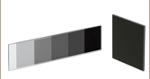
Thorlabs' One-Axis Rectangular Optic Mounts accept rectangular optics up to 4.0 mm (0.16") thick. The XF50(/M) offers 50 mm of travel and can mount optics from 12.7 mm (0.50") to 76.2 mm (3.00") wide. The XF100(/M) offers 100 mm of travel and can mount optics from 12.7 mm (0.50") to 126.2 mm (4.97") wide. These mounts are designed for use with our selection of resolution, distortion, slant edge, and calibration test targets. In addition, they are also compatible with our rectangular microscope slides, filters, dichroic mirrors, variable ND filters, and fluorescence imaging filters.
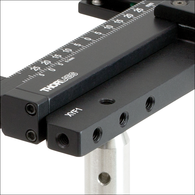
The actuator on the side of each mount enables travel along a single axis. The actuator can be adjusted by hand or with a 5/64" (2.0 mm) hex key (not included). A vernier scale that provides a resolution of 100 µm allows for repeatable positioning of the mounted optic. The actuator can be locked by a side-located 5/64" (2.0 mm) hex setscrew. Seven 8-32 (M4) tapped holes support several possible mounting orientations when used with our Ø1/2" posts. The three tapped holes along the front face of the mount are through holes allowing a post to be mounted on either side. Three of the mounting faces feature tapped holes spaced so that two Ø1/2" posts in post holders can be used next to each other for added stability.
Optics are secured with two support arms that each contain two nylon-tipped setscrews with a 5/64" (2.0 mm) hex. Each support arm can slide along a channel in the mount to accommodate different optic sizes; a 5/64" (2.0 mm) hex setscrew is used to lock each support arm in place. This mounting mechanism can be seen in the photo to the upper right. By loosening the top locking screws, the arms can be removed from the channel and interchanged, as shown in the image to the bottom left. When reattaching the arms, simply align each locking screw with one of the 2-56 captive nuts in the channel and tighten. This feature is useful in applications that require the target to be positioned close to a lens or other optical element in a system.
Please note that the support arms overlap the optic by 4.4 mm on each side.
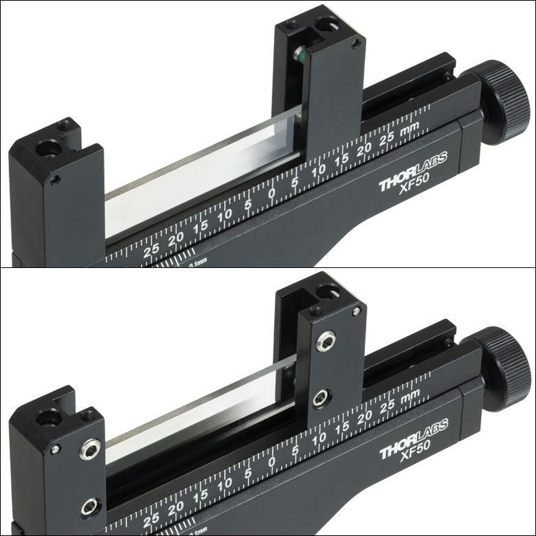
Click for Details
The support arms can be removed from the channel and interchanged by loosening the locking screws.
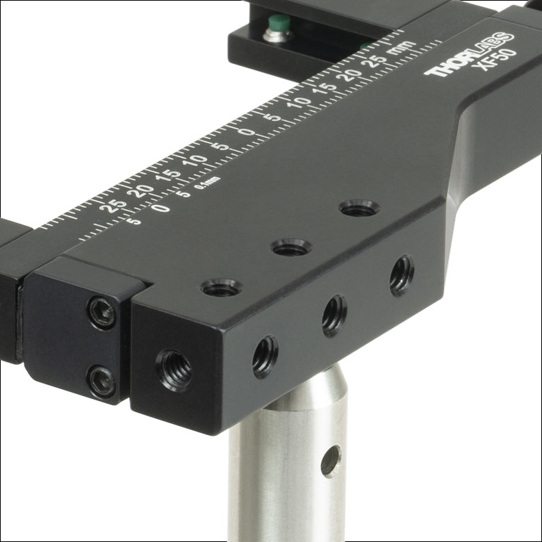
Click to Enlarge
Each mount has seven 8-32 (M4) taps, allowing for several post-mountable orientations (see images to the right).
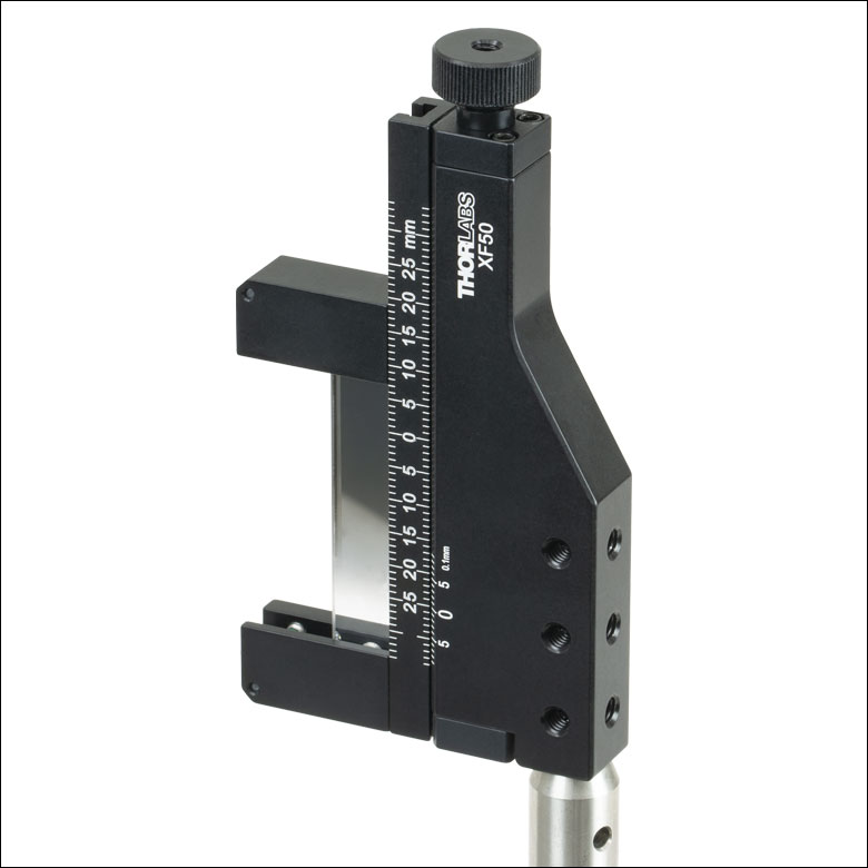
These Rectangular Optic Mounts can be used to position a rectangular optic horizontally, vertically, or perpendicular to the post axis and can be mounted using one or two posts.

 Zoom
Zoom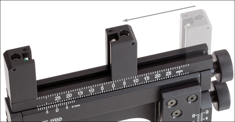
Click to Enlarge
A channel on the XYF1(/M) mount allows for translation of the lockable support arms for accommodating optics with different widths.
Click to Enlarge
The push bar on the XYF2(/M) mount moves the spring clips out to install a rectangular optic.
- Two Sizes Available
- XYF1(/M): 1/2" (12.7 mm) to 3" (76.2 mm) Wide Rectangular Optics with a Max Thickness of 0.16" (4 mm)
- XYF2(/M): 2.95" (75.0 mm) to 3.03" (77.0 mm) Wide, 0.98" (25.0 mm) to 3.03" (77.0 mm) Tall Optics with a Thickness of 0.04" (1.0 mm) to 0.07" (1.7 mm)
- 50 mm (1.97") Horizontal Travel and 30 mm (1.18") Vertical Travel
- Each Axis Includes a Vernier Scale that Provides 100 µm Resolution
- 8-32 (M4) Tapped Holes Support Six Post-Mounted Orientations
Thorlabs' XYF1(/M) Two-Axis Mount accepts a 1/2" (12.7 mm) to 3" (76.2 mm) wide rectangular optic up to 0.16" (4 mm) thick. The XYF2(/M) Two-Axis Mount accepts 2.95" (75.0 mm) to 3.03" (77.0 mm) wide, 0.98" (25.0 mm) to 3.03" (77.0 mm) tall, and 0.04" (1.0 mm) to 0.07" (1.7 mm) thick microscope slides and other optics. The mounts are ideal for general applications as well as home-built microscopy systems. The XYF1(/M) is designed for use with our selection of resolution, distortion, slant edge, and calibration test targets. In addition, it is also compatible with our rectangular microscope slides, filters, dichroic mirrors, variable ND filters, and fluorescence imaging filters. While the XYF2(/M) was designed for use with our microscope slides, it may also be used with a select range of resolution, distortion, and calibration test targets as well as filters and fluorescence imaging filters that do not exceed the size parameters. Alternatively, to accommodate other optic shapes and sizes, Thorlabs' XYA1(/M) translation adapter provides the same translation range as the XYF1(/M) and XYF2(/M) mounts, but features counterbores and threaded holes for mounting a fixed optic mount, such as a fixed filter holder.
Two actuators on the side of the mount enable manual positioning over a 50 mm (1.97") x 30 mm (1.18") area. These actuators can be adjusted by hand or with a 5/64" (2 mm) hex key (not included). Each axis of translation is equipped with a vernier scale that provides a resolution of 100 µm, allowing for repeatable positioning of the mounted optic. Each actuator can be locked by a 5/64" (2 mm) hex setscrew. Five 8-32 (M4) tapped holes support six possible mounting orientations when used with our Ø1/2" posts, of which a selection are shown below.
Optics are secured with two support arms that each contain two 5/64" (2 mm) hex, nylon-tipped setscrews. Each support arm can slide along a channel in the mount to accommodate different optic sizes; a 5/64" (2 mm) hex setscrew is used to lock each support arm in place. This mounting mechanism can be seen in the photo to the upper right. By loosening the top locking screws, the arms can be removed from the channel and reversed, as shown in the image to the bottom left. When reattaching the arms, simply align each locking screw with one of the 2-56 captive nuts in the channel and tighten. This feature is useful in applications that require the target to be positioned close to a lens or other optical element in a system. Please note that the support arms overlap the optic by 4.4 mm on each side.
Optics are secured in the XYF2(/M) mount using two fixed spring clips. Please note that the distance between the two cannot be adjusted. To install a microscope slide in the XYF2(/M) mount, gently press on the push bar, lifting up the spring clips, and slide the optic in (see photo to the right). A 1.3 mm (0.05") hex setscrew below each spring clip allows fine adjustment of the distance between it and the back plate.

Click for Details
The support arms on the XYF1(/M) mount can be removed from the channel and reversed by loosening the locking screws.
Click to Enlarge
The mounts have five 8-32 (M4) taps, allowing for six post-mountable orientations (see images to the right).
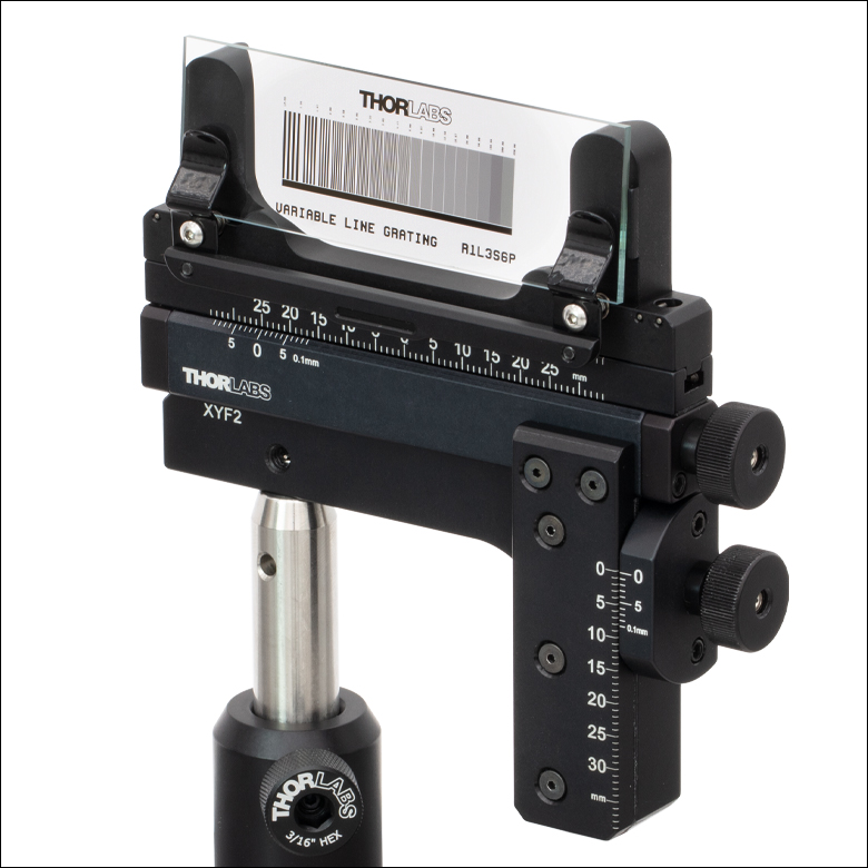
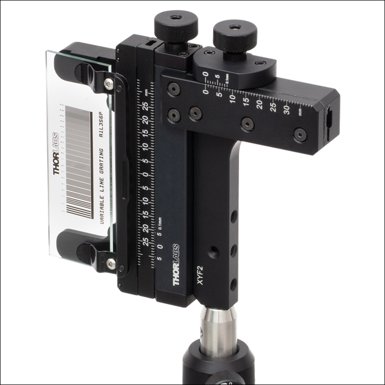
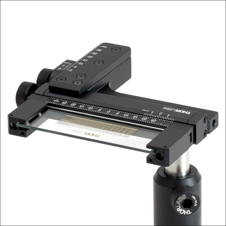
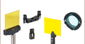
The XYF2(/M) (left and middle) and XYF1(/M) (right) mounts can be used to position a rectangular optic
(Item # R1L3S6P) horizontally, vertically, or perpendicular to the post axis.