 Products Home / Telecommunications Instruments / Transmitters / Fiber-Optic, Calibrated Electrical-to-Optical Converters
Fiber-Optic, Calibrated Electrical-to-Optical Converters

- Integrated Laser, Modulator, and Automatic Bias Control
- Traceable Calibrated Response from DC to 40 GHz, 70 GHz, or 110 GHz
- Optical Accessory for Electrical Vector Network Analyzer (VNA)
- Single-Laser and Dual-Laser Models
An E-O converter provides optical test capability for
an all-electrical vector network analyzer (VNA).
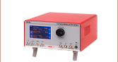
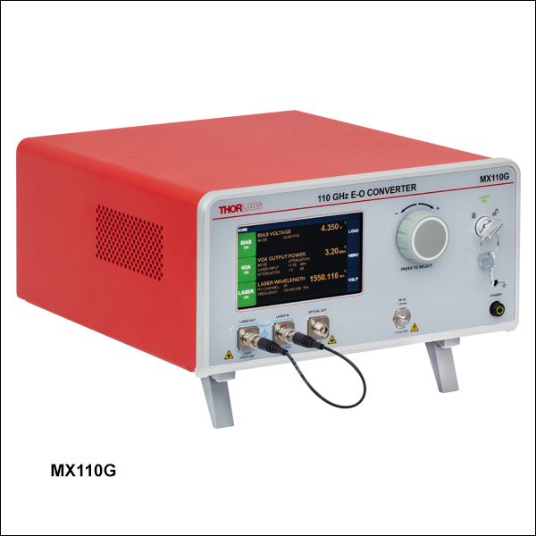
MX110G E-O Converter with Industry Leading Bandwidth of 110 GHz


Please Wait
| E-O Converter Selection Guide | ||||
|---|---|---|---|---|
| Item # | Speeda | Internal Laser Type |
Internal Laser Wavelength |
Internal Modulator (Type) |
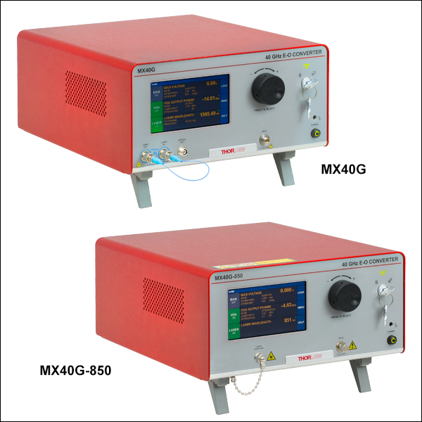
| MX40G-850 | 40 GHz | Fixed Wavelength | 852 nm | Intensity |
| MX40G-1310 | 40 GHz | Fixed Wavelength | 1310 nm | |
| MX40G | 40 GHz | C-Band, Tunableb | 1527.6 - 1565.5 nm | |
| MX40G-LB | 40 GHz | L-Band, Tunableb | 1570.0 - 1608.8 nm | |
| MX70G-1310 | 70 GHz | Fixed Wavelength | 1310 nm | |
| MX70G | 70 GHz | C-Band, Tunableb | 1527.6 - 1565.5 nm | |
| MX70G-LB | 70 GHz | L-Band, Tunableb | 1570.0 - 1608.8 nm | |
| MX70G-DB1 | 70 GHz | Fixed Wavelength | 1310 nm | |
| C-Band, Tunableb | 1527.6 - 1565.5 nm | |||
| MX110G-1310 | 110 GHz | Fixed Wavelength | 1310 nm | |
| MX110G | 110 GHz | C-Band, Tunableb | 1527.6 - 1565.5 nm | |

Janis Valdmanis, Ph.D. Optics
Ultrafast Optoelectronics
General Manager
Got Questions?
Our engineers and expertise
are here for you!
If you are not sure whether our catalog items meet your needs, we invite you to contact us. Or ask about a loan, so you can try them out for yourself, in your own lab. We can also support custom or OEM requirements you may have.
Just press the button, and we'll get back to you within the next business day.


Features
- Industry Leading Bandwidths of up to 110 GHz
- Enables E-E Test Equipment to Characterize O-E Devices
- Control via Intuitive Touchscreen Interface or Remotely Using USB or RS-232 Connections
- Mach-Zehnder Intensity Modulator and Bias Controller with Manual and Fully Automatic Operation Modes
- Variable Optical Attenuator (VOA) for Automatic or Manual Power Control
- S21 De-Embedding Parameters Supplied (*.s2p File)
- Integrated Fixed Wavelength or Tunable Laser
- Supports Operation with User-Supplied External Laser (Excluding Item # MX40G-850)
- Custom Configurations Available by Contacting the Ultrafast Optoelectronics Team
Thorlabs' Calibrated Electrical-to-Optical (E-O) Converters generate optical signals from electrical inputs. One of the primary applications of an E-O converter is enabling electrical-to-electrical (E-E) test equipment to characterize optical-to-electrical (O-E) devices. These calibrated E-O converters are particularly well suited for use as accessories providing optical test capability for an E-E VNA, as is illustrated at the top of this page. Particularly, the MX110G series E-O converters feature an industry leading bandwidth up to 110 GHz. With each converter, Thorlabs provides a *.s2p file containing S21 magnitude and phase data for the modulator across its frequency range of operation. These data can be used for either simple magnitude correction of the response or for complete de-embedding of the O-E device under test's response from the full E-E test system response. Please see Thorlabs' application note on de-embedding procedures for a detailed explanation.
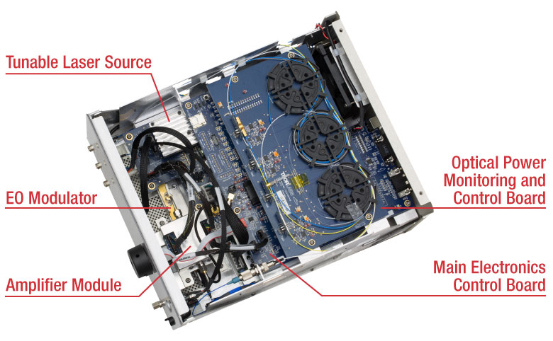
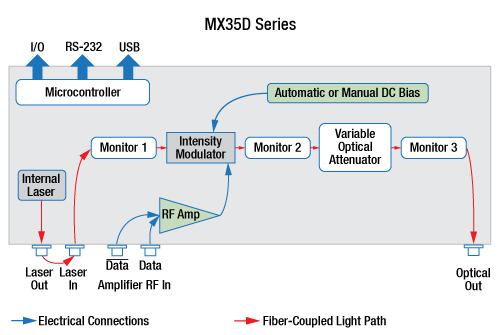
Each converter's telecom-grade components include a lithium niobate (LiNbO3) modulator stabilized by a fully automatic bias controller and a tunable or fixed-wavelength laser source. Variable optical attenuators (VOAs) and power monitors enable completely automated output power control and stabilization. The key elements of the converters are shown in the diagrams below.
The E-O converters include either a C-band or L-band laser tunable on the ITU 50 GHz grid or a fixed-wavelength laser. See the table on the right or Specs tab for details. Both internal tunable laser options feature a frequency offset option that allows for fine tuning by ±30 GHz in increments of 1 MHz and a dither feature for wavelength stabilization.
An external laser source can also be used to provide the optical input; please see the Specs tab for details on the acceptable wavelength range and maximum input powers for each converter. The laser input port uses polarization-maintaining (PM) PANDA fiber with light linearly polarized along the slow axis (aligned to the connector key). Note that single mode (SM) fiber is used at the optical output. Each fiber bulkhead accepts FC/PC connectors. For complete specifications, please see the Specs tab.
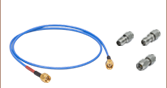
The Modulator RF In port of each converter fits specific coaxial connector sizes that are compatible with the bandwidth and high frequency response of each converter (see the Specs tab for details). Please note that at these high frequencies, cable length has an effect on overall system bandwidth, and care should be taken to use the shortest cable possible. Additionally, a torque wrench with the correct preset torque value should always be used to mate these coaxial connectors. Thorlabs' complete selection of compatible microwave cables and adapters can be viewed here.
These converters can be controlled in one of two ways. The simplest method is by using the intuitive touchscreen interface, which gives the user complete control over all instrument functionality. These instruments can also be operated remotely via the RS-232 or USB ports on the back panel. The Operation tab describes the graphical user interface (GUI) and user-customizable features, and we provide a remote control user guide and a remote control software tool (see the Software tab) for download.
Thorlabs offers a large selection of transmitter instruments; please see the Selection Guide tab above for all of our options.
Click to Enlarge
A block diagram showing the internal setup of the E-O converters for all models except
Item # MX70G-DB1.
Click to Enlarge
A block diagram showing the internal setup of the MX70G-DB1 Dual-Band E-O Converter.
| General System Specifications | |||||||
|---|---|---|---|---|---|---|---|
| Item # | MX40G-850 | MX40G MX40G-LB MX40G-1310 |
MX70G MX70G-LB MX70G-1310 MX70G-DB1 |
MX110G-1310 | MX110G | ||
| Frequency Responsea (Click for Plot) |
DC - 40 GHz | DC - 40 GHz | DC - 70 GHz | DC - 110 GHz | |||
| Uncertainty of Supplied Magnitude Responsea |
40 MHz to 20 GHz: ±1.20 dB 20 GHz to 40 GHz: ±2.30 dB |
40 MHz to 40 GHz: ±0.85 dB |
40 MHz to 40 GHz: ±0.85 dB 40 GHz to 70 GHz: ±1.75 dB |
40 MHz to 70 GHz: ±1.48 dB 70 GHz to 110 GHz: ±1.78 dB |
|||
| Input RF Connector Type | 2.92 mm Connectorb | 1.85 mm Connectorc | 1.0 mm Connectord | ||||
| Optical Output Powere (Biased for Peak Optical Output) |
4.5 dBm | MX70G-DB1: 7.5 dBm at 1550 nm, 5.5 dBm at 1310 nm; All Others: 8.5 dBm at 1550 nm, 6.5 dBm at 1310 nm |
6 dBm | ||||
| Internal Laser | (See Table Below) | ||||||
| External Laserf |
Wavelength Rangeg | N/A | 1250 nm - 1610 nm | 1260 nm - 1360 nm | 1525 nm - 1575 nm | ||
| Optical Input Power | N/A | 20 dBm (Max); 22 dBm (Absolute Max) | 17 dBm (Max); 20 dBm (Absolute Max) | ||||
| Power Calibration Points | 850 nm | 1310 nm, 1550 nm, and 1590 nm | 1310 nm | 1550 nm | |||
| RF Optical Extinction Ratio | 13 dB (Typical Max) | - | - | ||||
| DC Optical Extinction Ratio | - | 15 dB (Typical) | 20 dB (Typical) | ||||
| Modulator Drive Voltage (Vπ) | 4.8 Vpp at 1 GHz | 5.5 Vpp at 1 GHz | 2.5 Vpp at 1 MHz; 2.8 Vpp at 2 GHz |
3.3 Vpp at 1 MHz; 3.7 Vpp at 2 GHz |
|||
| Optical Insertion Loss (Typical)h | 5.5 dB | 5.0 dB (1550 nm); 7.0 dB (1310 nm) |
11 dB | ||||
| Absolute Stabilityi | 0.2 dB (Dither Mode)j | 0.20 dB (Dither Mode); 0.25 dB (Ratio Mode)k |
0.40 dB (Ratio Mode)k | 0.20 dB (Ratio Mode)k | |||
| Relative Stabilityl | 0.2 dB (Dither Mode)j | 0.2 dB (Dither Mode); 0.2 dB (Ratio Mode)k |
0.20 dB (Ratio Mode)k | ||||
| Internal Optical Fiber | SM Port: 780HP | PM Ports: PM1310-XP; SM Port: SMF-28 |
|||||
| Fiber Connectors | FC/PC, 2.0 mm Narrow Key | ||||||
| Power Monitor and VOAa Specifications | |
|---|---|
| Power Monitor Accuracyb | ±0.5 dBm |
| Power Monitor Resolution | 0.01 dBm |
| Power Monitor Insertion Loss | 0.1 dB (Typical per Monitor) |
| VOA Attenuation Range | 1 dB - 20 dB |
| VOA Response Time | 1 s |
| Power and Environmental Specifications | |
|---|---|
| Main AC Voltage | 100 VAC - 250 VAC |
| Power Consumption | 60 VA |
| Line Frequency | 50 Hz - 60 Hz |
| Operating Temperature | 10 to 40 °C |
| Storage Temperature | 0 to 50 °C |
| Relative Humiditya | 5% to 85% |
Click to Enlarge
Frequency noise spectrum of the integrated C-band and L-Band tunable lasers. The dither function helps stabilize the wavelength but increases noise.
| Internal Laser Specificationsa | ||||||||
|---|---|---|---|---|---|---|---|---|
| Item # | MX40G-850 | MX40G-1310 MX70G-1310 |
MX40G MX70G |
MX40G-LB MX70G-LB |
MX70G-DB1 | MX110G-1310 | MX110G | |
| Laser Type | Fixed Wavelength | Fixed Wavelength | C-Band Tunable Wavelength | L-Band Tunable Wavelength | Fixed Wavelength | C-Band Tunable Wavelength | Fixed Wavelength | C-Band Tunable Wavelength |
| Wavelength | 852 nm | 1310 nm | 1527.6 - 1565.5 nm | 1570.0 - 1608.8 nm | 1310 nm | 1527.6 - 1565.5 nm | 1310 nm | 1527.6 - 1565.5 nm |
| Frequency Range | - | 191.50 - 196.25 THz | 186.35 - 190.95 THz | - | 191.50 - 196.25 THz | - | 191.50 - 196.25 THz | |
| Optical Output Power | 10 dBm | 13.5 dBm | 13.5 dBm | 12.5 dBm | 12.5 dBm | 17 dBm | ||
| Frequency Accuracy | - | ±1.5 GHz | - | ±1.5 GHz | - | ±1.5 GHz | ||
| Tuning Resolution | N/A | 50 GHz | N/A | 50 GHz | N/A | 50 GHz | ||
| Fine Tuning Resolution | N/A | 1 MHz | N/A | 1 MHz | N/A | 1 MHz | ||
| Tuning Speed (Between Wavelengths) | N/A | 10 s | N/A | 10 s | N/A | 10 s | ||
| Fine Tuning Range | N/A | ±30 GHz | N/A | ±30 GHz | N/A | ±30 GHz | ||
| Side Mode Suppression Ratio | 35 dB (Min) | 55 dB | 35 dB (Min) | 55 dB | 45 dB | 55 dB | ||
| Optical Signal to Noise Ratio | - | 60 dB | - | 60 dB | - | 60 dB | ||
| Intrinsic Linewidth | 2 MHz | 10 kHz | 2 MHz | 10 kHz | 10 MHz (Max) | 10 kHz | ||
| Relative Intensity Noiseb | - | -145 dB/Hz (Max) | - | -145 dB/Hz (Max) | - | -145 dB/Hz (Max) | ||
| Back Reflection | - | -14 dB (Max) | - | -14 dB (Max) | - | -14 dB (Max) | ||
| Polarization Extinction Ratio | 20 dB | 18 dB (Min) | 20 dB | 18 dB (Min) | 20 dB | 18 dB (Min) | ||
System Overview
Each calibrated E-O converter is fully integrated and contains a laser source and a lithium niobate (LiNbO3) Mach-Zehnder intensity modulator with automatic bias controller; the only required external input is the signal source to the Modulator RF In port. Either the internal laser or an external laser source may be coupled to the Laser In port, which can be seen in the bottom-left corner of the diagram below. This port uses polarization maintaining (PM) fiber with light linearly polarized along the slow axis, as shown on the front panel of the instrument. Note that this loop-back is not available for the MX40G-850 converter. Optical power is monitored in three places (Monitor 1, Monitor 2, and Monitor 3) for the purpose of enabling bias and power control. These power values are also available at the I/O port on the back panel of the instrument. Monitor 1 is at the laser input, Monitor 2 is at the output of the modulator, and Monitor 3 is at the final optical output.
Click to Enlarge
A block diagram showing the internal setup of the E-O converters for all models except Item # MX70G-DB1.
Click to Enlarge
A block diagram showing the internal setup of the MX70G-DB1 Dual-Band E-O converter.
De-Embedding Procedures
Click to Enlarge
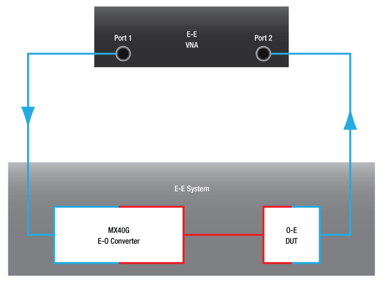
Figure 2: The E-E system response measured by the E-E VNA is the combined response of the E-O converter and the O-E DUT. Blue indicates electrical connections and red is used for optical connections.
Click to Enlarge
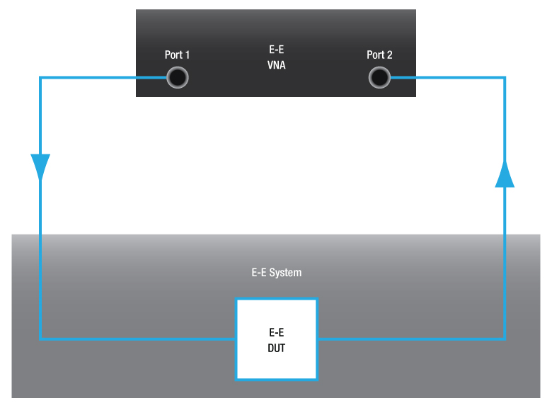
Figure 1: The E-E system response measured by the E-E VNA is the response of the E-E DUT. Blue indicates electrical connections.
One of the primary applications of a calibrated electrical-to-optical (E-O) converter is enabling electrical-to-electrical (E-E) test equipment, like a vector network analyzer (VNA), to characterize optical-to-electrical (O-E) devices. E-E test equipment connects to and tests E-E systems as illustrated in Figure 1. As shown in Figure 2, the device is used to convert the electrical signal from Port 1 of the E-E VNA to an optical signal that is input into the O-E device under test (DUT), and the electrical signal resulting from the O-E DUT is then provided to Port 2 of the E-E test equipment. The response of the entire E-E system, which consists of the E-O converter and the O-E DUT together, is measured. Accurately recovering the response of the O-E DUT requires removing the response of the converter from the measured E-E system response. This is referred to as de-embedding.
Thorlabs provides a file (*.s2p format) with every calibrated E-O converter that contains the S21 magnitude and phase response of the modulator across its frequency range of operation. These data are used to perform the de-embedding process. Note that most modern E-E VNA systems provide a built-in function for doing this type of de-embedding based on the user-supplied *.s2p file. This is the easiest method. However, the de-embedding process can also be performed manually. These methods are described in detail in the application note.
Please click on the Specs tab to see typical frequency response plots for our converters.
Instrument Control
The graphical user interface (GUI) gives the user complete control over all instrument functionality. Each E-O converter uses a resistive touchscreen display sensitive to both finger pressure and taps from a plastic stylus. The knob on the front panel of the housing can be used in place of the on-screen arrow buttons to quickly change setpoint values. Pressing (clicking) the knob will confirm a new setpoint value. Additionally, the instruments can be driven using serial commands delivered via connectors on the rear panel. This is described in the remote control user guide, and a Windows program that demonstrates remote control of the converter is available in the Software tab.
Click to Enlarge
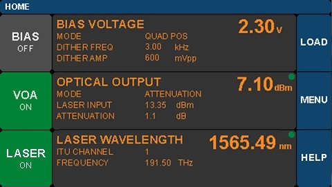
Figure 3: Home Screen of the E-O Converter
The home screen of the converter, shown in Figure 3, is organized into three main sections. The green dot that appears in the upper-right of the center column panels indicates that those functions are stable. The dot will blink if that function is still stabilizing.
- Left Column:
- Buttons show the on/off status of the different instrument functions.
- Tap a button to toggle the function on/off.
- Middle Column:
- Current operating parameters of each control function are shown.
- Tap in this column to access the settings page for each function.
- Right Column:
- Buttons provide access to various utility and help functions.
- Tap to review and customize system settings.
Functions and controls enabled by the GUI are further discussed in the following sections.
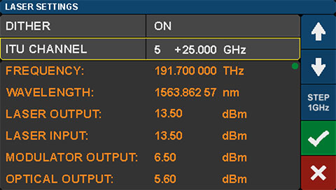
Laser Settings
Click to Enlarge
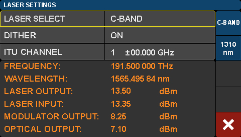
Figure 5: Laser Settings Screen for the MX70G-DB1 Dual-Band E-O converter
Click to Enlarge
Figure 4: Laser Settings Screen for Tunable Laser Models Except Item # MX70G-DB1
Note: This section does not apply to the MX40G-850, MX40G-1310, MX70G-1310, and MX110G-1310 converters, which contain only fixed-wavelength lasers that do not have configurable settings.
The laser setting screens shown in Figures 4 and 5 are accessed directly from the home screen. Each single-band instrument includes either a C- or L-band telecom-style laser that is tunable on the ITU 50 GHz grid. The MX70G-DB1 dual- band instrument includes both a C-band tunable laser and a 1310 nm fixed wavelength laser. As shown in Figure 5, the laser source is selectable on the far right of the screen.
The C-band and L-band lasers support a fine tuning frequency offset feature, allowing the frequency to be adjusted by an offset from -30.000 GHz to +30.000 GHz in increments of 1 MHz. ITU Channel wavelengths are indexed for convenience; use the arrow buttons to step through the indices to select the desired wavelength.
This screen also allows the user to control whether or not the dither feature (available for tunable C- and L-band lasers only) is used to stabilize the wavelength. Turning dither off results in lower phase and intensity noise (see the Specs tab for a representative plot), but doing so may also result in the wavelength drifting slightly over time. If an external laser is used, the internal laser can be turned off by tapping the laser button on the home screen.
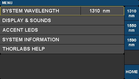
System Wavelength Settings
Click to Enlarge
Figure 6: System Wavelength Selection Screen
Note: This section does not apply to the MX40G-850, MX110G, or MX110G-1310 converters. The MX40G-850 converter has a single calibration wavelength of 850 nm and no external laser input. The MX110G and MX110G-1310 converters have single calibration wavelengths of 1550 nm and 1310 nm, respectively.
If an external laser is used instead of the internal laser, it may be necessary to change the power monitor calibration settings. The MX40G and MX70G series converters can be used at wavelengths anywhere between 1250 nm and 1610 nm, and calibration settings are supplied for three wavelengths: 1310 nm, 1550 nm, and 1590 nm. These wavelengths represent the centers of the O-Band, C-Band, and L-Band. The default calibration setting corresponds to the wavelength range of the internal laser. If operating outside that wavelength range, change the power monitor calibration settings by tapping the Menu button on the home page. Select the System Wavelength setting, shown in Figure 6, to change the power monitor calibration wavelength to the value closest to the wavelength of the laser source being used.
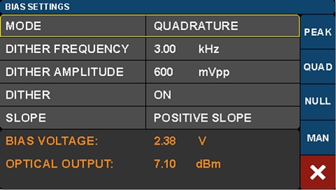
Modulator Bias Controller
Click to Enlarge
Figure 8: Bias Settings Screen
Click to Enlarge
Figure 7: Bias Points for an Intensity Modulator, in which Vπ is the Half-Wave Voltage
There are four bias control modes, which provide the option of operating with fully automatic bias control or under manual control. Three of the four automated operating modes, Peak, Quadrature, and Null, reference the regions labeled on the modulation transmission function, which is illustrated in Figure 7. When one of these modes is selected, a dither tone is used to hold the modulator at the respective bias point. The dither tone is part of a lock-in approach that maintains a stable bias point by compensating for modulator drift, which occurs over time due to the temperature sensitivity of the modulator. The dither tone can be set to a frequency between 1 and 10 kHz, and the amplitude of the tone can also be selected. Quadrature mode gives the option of operating on either the positive or negative slope of the function.
Note: The Quadrature bias mode of the MX110G series of converters does not have a dither option and operates similarly to the Constant Ratio mode described below, except the setpoint is calculated during the calibration routine and is not user adjustable.
For those applications that require an automated, but ditherless, approach to maintaining a stable bias setpoint, select the Constant Ratio mode. It is enabled by tapping the MAN function on the right of the screen shown in Figure 8 and configuring the Ratio Setpoint and Slope values. This mode adjusts the bias voltage to maintain a chosen ratio between the intensity values reported by Monitor 1 and Monitor 2. The Slope setting allows the user to choose whether increasing voltage on the modulator increases or decreases the optical output power.
It can be useful to operate for brief periods of time at a bias fixed voltage and without a dither tone. A fixed bias voltage can be applied in one of two ways. When operating in Quadrature, Peak, or Null modes, tapping the value of Dither will toggle it between on and off states. When dither is toggled off, the value of the fixed bias voltage is held at the most recent automated bias voltage. This enables the user to make quick measurements, without the dither tone present, while the modulator is biased at one of the common modulator transmission function setpoints. The Constant Bias mode can also be accessed by tapping the Mode value and then the MAN function on the right of the screen. This page allows either the automated Constant Ratio or fixed-voltage Constant Bias modes to be enabled and configured.
Variable Optical Attenuator
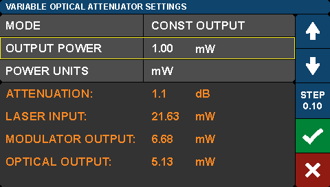
Click to Enlarge
Figure 9: VOA Settings Screen
The VOA provides the means for adjusting and stabilizing the modulated optical output power. The VOA settings screen, which is shown in Figure 9, allows the user to choose between and adjust the parameters of the two operational modes. In Constant Attenuation mode, the attenuation level between the Return from Modulator input port and the Final Optical Output port is fixed, which allows power fluctuations at the input of the power controller to be transferred to the output. In Constant Output Power Mode, the final optical output power is held constant independent of the input fluctuations. In this mode, the VOA is effectively used as a power stabilizer. Tap the Step function button at the right of the screen to change the step size by which the arrows increment or decrement the setpoint values.
The VOA settings screen also allows the user to select the units used to report the power readings and parameters on all pages. Use the Power Units field to choose whether power values are reported as mW or dBm.
Rear Panel
The rear panel provides additional safety and utility functions such as the laser safety interlock and the power monitor output, RS-232, and USB ports. Both the USB and RS-232 interfaces can be used for remote control operation of the E-O converter. The serial commands and control features available are fully described in the Remote Control User Guide. The USB interface is also used for installing firmware upgrades as they become available.
All units are shipped from Thorlabs with a shorting device that is already installed in the interlock connector, thus allowing the instrument to be operated normally right out of the box. To make use of the interlock feature, a 2.5 mm plug can be wired to the remote interlock switch and plugged into the back-panel interlock jack in place of the shorting plug. Electrical specifications for this function are provided in the manual.
Front Panels
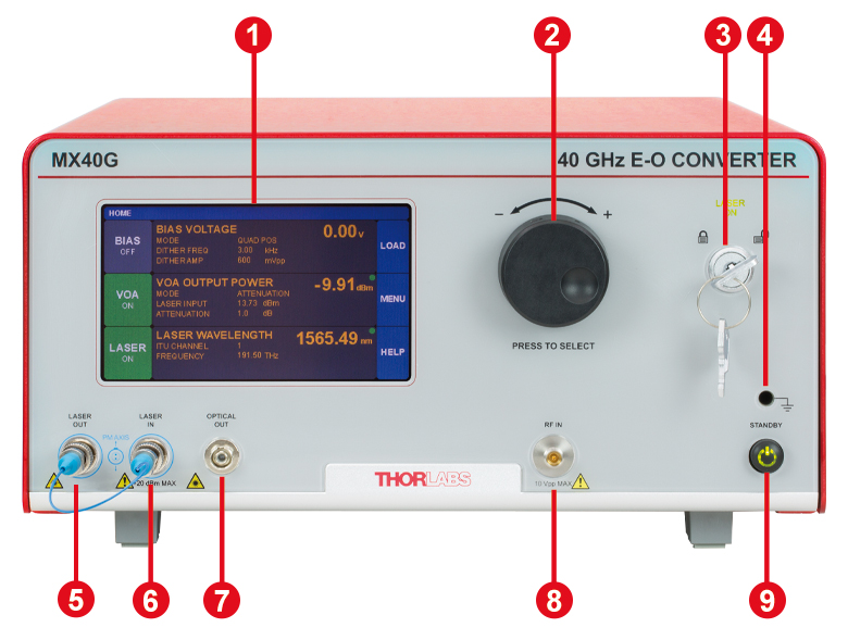
Click to Enlarge
E-O Converter Front Panel (Except MX40G-850)
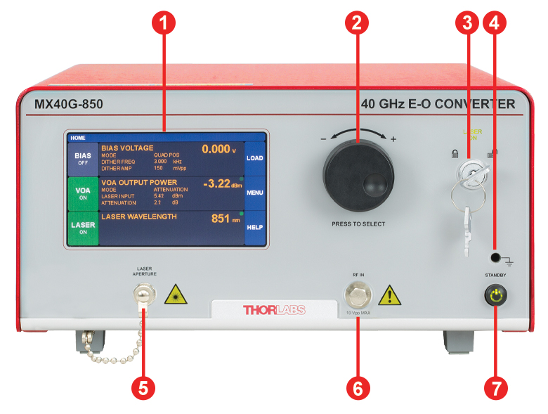
Click to Enlarge
MX40G-850 E-O Converter Front Panel
| Callout | Description |
|---|---|
| 1 | Touchscreen Display and Control |
| 2 | Value Adjustment Knob |
| 3 | Key Switch and Status Indicator Light for Internal Laser |
| 4 | Earth Ground Port for ESD Wrist Strap Banana Plug |
| 5a,b | Laser Out for Internal Laser Source, Accepts PM Fiber with FC/PC Connector |
| 6a,b | Laser In to Modulator, Accepts PM Fiber with FC/PC Connector |
| 7c | Optical Out: Final Output from Modulator |
| 8d | Modulator RF In: Signal to Modulator, MX40G Series: 2.92 mm Femalee MX70G Series: 1.85 mm Femalef MX110G Series: 1.0 mm Femaleg |
| 9 | On/Standby Button |
| Callout | Description |
|---|---|
| 1 | Touchscreen Display and Control |
| 2 | Value Adjustment Knob |
| 3 | Key Switch and Status Indicator Light for Internal Laser |
| 4 | Earth Ground Port for ESD Wrist Strap Banana Plug |
| 5a | Optical Out: Final Output from Modulator |
| 6b | Modulator RF In: Signal to Modulator, 2.92 mm Female |
| 7 | On/Standby Button |
Back Panel
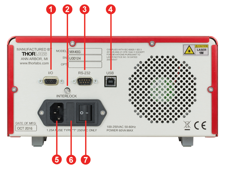
Click to Enlarge
E-O Converters Back Panel
| Callout | Description |
|---|---|
| 1a | I/O Control Port (DB15 Connector) Outputs from Three Integrated Power Monitors |
| 2 | Laser Interlock Jack (2.5 mm Phono Jack) |
| 3a | RS-232 Control Port |
| 4 | USB Port (Type B) |
| 5 | AC Power Cord Connector |
| 6 | Fuse Tray |
| 7 | AC Power Switch |
I/O DB15 Connector
The I/O connector provides analog outputs from the three power monitors.
| Pin | Description | Pin | Description |
|---|---|---|---|
| 1 | Power Monitor 1 | 9 | Analog Ground |
| 2 | Power Monitor 2 | 10 | Analog Ground |
| 3 | Power Monitor 3 | 11 | Reserved for Future Use |
| 4 | Reserved for Future Use | 12 | Reserved for Future Use |
| 5 | Analog Ground | 13 | Monitor 1 Gain Indicator |
| 6 | Analog Ground | 14 | Monitor 2 Gain Indicator |
| 7 | Analog Ground | 15 | Monitor 3 Gain Indicator |
| 8 | Analog Ground | - | - |
RS-232 Connector
The RS-232 connector is included to support remote operation.
| Pin | Description |
|---|---|
| 1 | Not Connected |
| 2 | RS-232 Input |
| 3 | RS-232 Output |
| 4 | Not Connected |
| 5 | Digital Ground |
| 6 | Not Connected |
| 7 | Not Connected |
| 8 | Not Connected |
| 9 | Not Connected |
USB Type B Connector
The USB connector is provided for firmware upgrades and remote operation.
Each Electrical-to-Optical Converter Includes:
- Calibrated E-O Converter Main Unit
- Power Cord According to Local Supply (Determined by Ordering Location)
- PM Loop-Back Fiber Optic Cable (Not Included with MX40G-850)
- Interlock Keys for Front Panel
- 2.5 mm Interlock Pin (Pre-installed in Back Panel)
- 1.25 A, 250 VAC Fuse
- USB Type A to Type B Cable, 6' Long
- USB Storage Device with *.s2p File Characterizing Instrument
Click to Enlarge
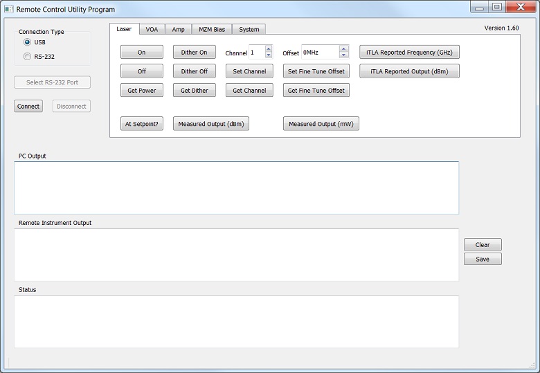
The GUI of the Remote Control Software Tool
Software for the MX40G, MX70G, and MX110G Series of Calibrated E-O Converters
Control the Converters Remotely via Serial Commands
Serial commands sent to the MX40G, MX70G and MX110G series of E-O converters can control the functionality of the internal laser, bias controller for the built-in modulator, and variable optical attenuator (VOA), as well as general system parameter settings. The commands can be sent from a computer running any operating system to the RS-232 port on the back panel of the device. Computers running Windows® 7, or later versions of the operating system, can send serial commands to the USB port on the back panel of the converter. The touchscreen interface remains active while the device is controlled remotely. Descriptions of how to connect a controlling computer to the converter, the serial command set, and descriptions of each command are included in the Remote Control User Guide.
Application Demonstrating GUI-Based Remote Control of the Converters
The Remote Control Software Tool, which is available for download, is an example graphical user interface (GUI) provided for testing, demonstrating, and exploring the use of the different serial commands. This program is not required to operate the converter remotely. It opens a connection to the device and sends commands in response buttons clicked by users. Commands sent to the converter, responses from the converter, and status informational messages are logged to the three rectangular fields located beneath the buttons. Please see the Remote Control User Guide for more information. This program can be used as a basis for the development of custom applications. Please
Software
Version 1.8.7 (May 5, 2022)
Click on the link below to download the Remote Control Software Tool.

Firmware Update
Version 1.8.3 (January 13, 2020)
Version 1.9.7 (May 13, 2022)
Version 2.0.3 (May 12, 2023)
Click on the link below to download the latest firmware. Version 1.8.3 is for all models except Item # MX70G-DB1, which uses Version 1.9.7, and the MX110G Series, which uses Version 2.0.3.

Laser Safety and Classification
Safe practices and proper usage of safety equipment should be taken into consideration when operating lasers. The eye is susceptible to injury, even from very low levels of laser light. Thorlabs offers a range of laser safety accessories that can be used to reduce the risk of accidents or injuries. Laser emission in the visible and near infrared spectral ranges has the greatest potential for retinal injury, as the cornea and lens are transparent to those wavelengths, and the lens can focus the laser energy onto the retina.
 |
 |
 |
 |
 |
 |
 |
 |
 |
Safe Practices and Light Safety Accessories
- Laser safety eyewear must be worn whenever working with Class 3 or 4 lasers.
- Regardless of laser class, Thorlabs recommends the use of laser safety eyewear whenever working with laser beams with non-negligible powers, since metallic tools such as screwdrivers can accidentally redirect a beam.
- Laser goggles designed for specific wavelengths should be clearly available near laser setups to protect the wearer from unintentional laser reflections.
- Goggles are marked with the wavelength range over which protection is afforded and the minimum optical density within that range.
- Laser Safety Curtains and Laser Safety Fabric shield other parts of the lab from high energy lasers.
- Blackout Materials can prevent direct or reflected light from leaving the experimental setup area.
- Thorlabs' Enclosure Systems can be used to contain optical setups to isolate or minimize laser hazards.
- A fiber-pigtailed laser should always be turned off before connecting it to or disconnecting it from another fiber, especially when the laser is at power levels above 10 mW.
- All beams should be terminated at the edge of the table, and laboratory doors should be closed whenever a laser is in use.
- Do not place laser beams at eye level.
- Carry out experiments on an optical table such that all laser beams travel horizontally.
- Remove unnecessary reflective items such as reflective jewelry (e.g., rings, watches, etc.) while working near the beam path.
- Be aware that lenses and other optical devices may reflect a portion of the incident beam from the front or rear surface.
- Operate a laser at the minimum power necessary for any operation.
- If possible, reduce the output power of a laser during alignment procedures.
- Use beam shutters and filters to reduce the beam power.
- Post appropriate warning signs or labels near laser setups or rooms.
- Use a laser sign with a lightbox if operating Class 3R or 4 lasers (i.e., lasers requiring the use of a safety interlock).
- Do not use Laser Viewing Cards in place of a proper Beam Trap.
Laser Classification
Lasers are categorized into different classes according to their ability to cause eye and other damage. The International Electrotechnical Commission (IEC) is a global organization that prepares and publishes international standards for all electrical, electronic, and related technologies. The IEC document 60825-1 outlines the safety of laser products. A description of each class of laser is given below:
| Class | Description | Warning Label |
|---|---|---|
| 1 | This class of laser is safe under all conditions of normal use, including use with optical instruments for intrabeam viewing. Lasers in this class do not emit radiation at levels that may cause injury during normal operation, and therefore the maximum permissible exposure (MPE) cannot be exceeded. Class 1 lasers can also include enclosed, high-power lasers where exposure to the radiation is not possible without opening or shutting down the laser. |  |
| 1M | Class 1M lasers are safe except when used in conjunction with optical components such as telescopes and microscopes. Lasers belonging to this class emit large-diameter or divergent beams, and the MPE cannot normally be exceeded unless focusing or imaging optics are used to narrow the beam. However, if the beam is refocused, the hazard may be increased and the class may be changed accordingly. |  |
| 2 | Class 2 lasers, which are limited to 1 mW of visible continuous-wave radiation, are safe because the blink reflex will limit the exposure in the eye to 0.25 seconds. This category only applies to visible radiation (400 - 700 nm). |  |
| 2M | Because of the blink reflex, this class of laser is classified as safe as long as the beam is not viewed through optical instruments. This laser class also applies to larger-diameter or diverging laser beams. |  |
| 3R | Class 3R lasers produce visible and invisible light that is hazardous under direct and specular-reflection viewing conditions. Eye injuries may occur if you directly view the beam, especially when using optical instruments. Lasers in this class are considered safe as long as they are handled with restricted beam viewing. The MPE can be exceeded with this class of laser; however, this presents a low risk level to injury. Visible, continuous-wave lasers in this class are limited to 5 mW of output power. |  |
| 3B | Class 3B lasers are hazardous to the eye if exposed directly. Diffuse reflections are usually not harmful, but may be when using higher-power Class 3B lasers. Safe handling of devices in this class includes wearing protective eyewear where direct viewing of the laser beam may occur. Lasers of this class must be equipped with a key switch and a safety interlock; moreover, laser safety signs should be used, such that the laser cannot be used without the safety light turning on. Laser products with power output near the upper range of Class 3B may also cause skin burns. |  |
| 4 | This class of laser may cause damage to the skin, and also to the eye, even from the viewing of diffuse reflections. These hazards may also apply to indirect or non-specular reflections of the beam, even from apparently matte surfaces. Great care must be taken when handling these lasers. They also represent a fire risk, because they may ignite combustible material. Class 4 lasers must be equipped with a key switch and a safety interlock. |  |
| All class 2 lasers (and higher) must display, in addition to the corresponding sign above, this triangular warning sign. |  |
|

Janis Valdmanis, Ph.D. Optics
Ultrafast Optoelectronics
General Manager
Custom and OEM Options
When your application requirements are not met by our range of catalog products or their variety of user-configurable features, please contact me to discuss how we may serve your custom or OEM needs.
Request a Demo Unit
Explore the benefits of using a Thorlabs high-speed instrument in your setup and under your test conditions with a demo unit. Contact me for details.
![]()
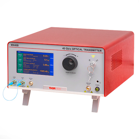
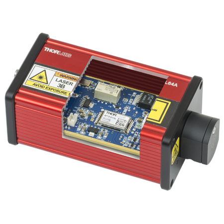
Click to Enlarge
The MX40B Digital Reference Transmitter
Design, Manufacturing, and Testing Capabilities
Thorlabs' Ultrafast Optoelectronics Team designs, develops, and manufactures high-speed components and instrumentation for a variety of photonics applications having frequency responses up to 110 GHz. Our extensive experience in high-speed photonics is supported by core expertise in RF/microwave design, optics, fiber optics, optomechanical design, and mixed-signal electronics. As a division of Thorlabs, a company with deep vertical integration and a portfolio of over 20,000 products, we are able to provide and support a wide selection of equipment and continually expand our offerings.
Our catalog and custom products include a range of integrated fiber-optic transmitters, modulator drivers and controllers, detectors, receivers, pulsed lasers, variable optical attenuators, and a variety of accessories. Beyond these products, we welcome opportunities to design and produce custom and OEM products that fall within our range of capabilities and expertise. Some of our key capabilities are:
- Detector and Receiver Design, to 70 GHz
- Fiber-Optic Transmitter Design, to 110 GHz
- RF & Microwave Design and Simulation
- Design of Fiber-Optic and Photonics Sub-Assemblies
- High-Speed Testing, to 110 GHz
- Micro-Assembly and Wire Bonding
- Hermetic Sealing of Microwave Modules
- Fiber Splicing of Assemblies
- Custom Laser Engraving
- Qualification Testing
Overview of Custom and Catalog Products
Our catalog product line includes a range of integrated fiber-optic transmitters, modulator drivers and controllers, detectors, pulsed lasers, and accessories. In addition to these, we offer related items, such as receivers and customized catalog products. The following sections give an overview of our spectrum of custom and catalog products, from fully integrated instruments to component-level modules.
Fiber-Optic Instruments
To meet a range of requirements, our fiber-optic instruments span a variety integration levels. Each complete transmitter includes a tunable laser, a modulator with driver amplifier and bias controller, full control of optical output power, and an intuitive touchscreen interface. The tunable lasers, modulator drivers, and modulator bias controllers are also available separately. These instruments have full remote control capability and can be addressed using serial commands sent from a PC.
- Fiber-Optic Transmitters, to 110 GHz
- Linear and Digital Transmitters
- Electrical-to-Optical Converters, to 110 GHz
- Modulator Drivers
- Modulator Bias Controllers
- C- and L-Band Tunable Lasers
Customization options include internal laser sources, operating wavelength ranges, optical fiber types, and amplifier types.
Fiber-Optic Components
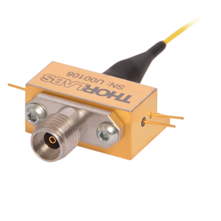
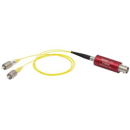
Our component-level, custom and catalog fiber-optic products take advantage of our module design and hermetic sealing capability. Products include detectors with frequency responses up to 50 GHz, and we also specialize in developing fiber-optic receivers, operating up to and beyond 40 GHz, for instrumentation markets. Closely related products include our amplifier modules, which we offer upon request, variable optical attenuators, microwave cables, and cable accessories.
- Hermetically-Sealed Detectors, to 50 GHz
- Fiber-Optic Receivers, to 40 GHz
- Amplifier Modules
- Electronic Variable Optical Attenuators
- Microwave Cables and Accessories
Customization options include single mode and multimode optical fiber options, where applicable, and detectors optimized for time or frequency domain operation.
Free-Space Instruments
Our free-space instruments include detectors with frequency responses around 1 GHz and pulsed lasers. Our pulsed lasers generate variable-width, nanosecond-duration pulses, and a range of models with different wavelengths and optical output powers are offered. User-adjustable repetition rates and trigger in/out signals provide additional flexibility, and electronic delay-line products enable experimental synchronization of multiple lasers. We can also adapt our pulsed laser catalog offerings to provide gain-switching capability for the generation of pulses in the 100 ps range.
- Pulsed Lasers with Fixed 10 ns Pulse Duration
- Pulsed Lasers with Variable Pulse Width and Repetition Rates
- Electronic Delay Units to Synchronize NPL Series Pulsed Lasers
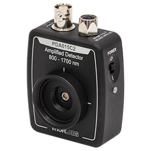
- Amplified Detectors
Customization options for the pulsed lasers include emission wavelength, optical output powers, and sub-nanosecond pulse widths.

Choose Optical Transmitter by Application
- Beginning at the left side of the table, choose your desired system characteristics.
- Follow the table to the right and continue to select characteristics from the options within the same row as your previous selection.
- After reaching a Base Item #, choose a laser type. Your system's item # will be your base item # combined with the suffix for your laser type, e.g. MX40B-1310.
| Start Here | Follow the Table to the Right and Choose From These Options | Find Your System Here | ||||
|---|---|---|---|---|---|---|
| Modulator Type | Primary Application | Modulation Format | Speed | RF Input | Base Item # | Item # Suffix: Laser Type |
| Amplitude | Time Domain / Eye Diagram | Linear / 4-Level PAM4 | 32 GBaud | Differential | MX35D | No Suffix: C-Band Tunable Laser -LB: L-Band Tunable Laser -1310: 1310 nm Fixed Laser -850: 850 nm Fixed Lasera,b |
| Single Ended | MX35E | |||||
| 56 GBaud | → | MX65E | ||||
| Digital / 2-Level NRZ / OOK | 10 Gbps | → | MX10B | |||
| 40 Gbps | → | MX40B | ||||
| 56 Gbps | MX50E | |||||
| 56 Gbps | → | MX65E | ||||
| Frequency Domain / VNA | → | 40 GHz | → | MX40G | ||
| 70 GHz | → | MX70G | ||||
| 110 GHz | → | MX110G | ||||
| Phase | → | → | 10 Gbps | → | MX10C | |
| 40 Gbps | → | MX40C | ||||
Choose Optical Transmitter Instrument by Features
| Transmitter Instruments and Tunable Lasers | |||||||
|---|---|---|---|---|---|---|---|
| Item # | Speed | Internal Laser | Internal Modulator (Type) |
RF Amplifier (Type) |
Bias Controller |
Variable Optical Attenuator (VOA) |
Block Diagram |
| Automatic Bias Controller | |||||||
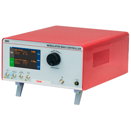
| MBX (770 - 980 nm) |
N/A | - | - | - |  |
||
| MBX2 (1250 - 1610 nm) |
N/A | - | - | - | |
||
| Tunable Telecom-Grade Laser Sources | |||||||
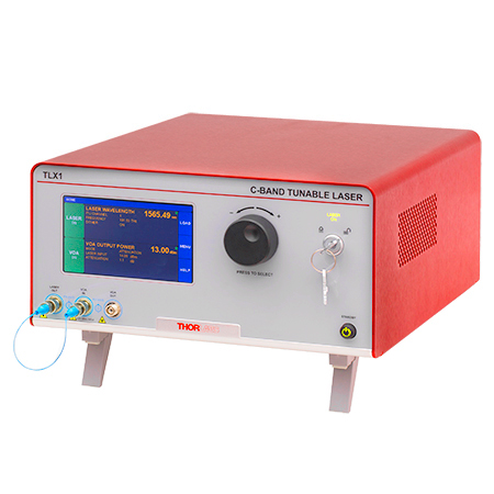
| TLX1 | N/A | C-Band, Tunable | - | - | - |  |
|
| TLX2 | N/A | L-Band, Tunable | |||||
| High-Speed Modulator Drivers | |||||||
| MX10A (1250 - 1610 nm) |
12.5 Gb/sa | - | - | Digital |  |
||
| MX40A (1250 - 1610 nm) |
40 Gb/sa | ||||||
| High-Speed Optical Transmitters | |||||||
| MX10B | 12.5 Gb/sa | C-Band, Tunable | Intensity | Digital | 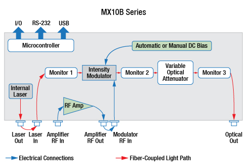 |
||
| MX10B-LB | 12.5 Gb/sa | L-Band, Tunable | |||||
| MX10B-1310 | 12.5 Gb/sa | 1310 nm, Fixed | |||||
| MX10C | 12.5 Gb/sa | C-Band, Tunable | Phase | Digital | - | 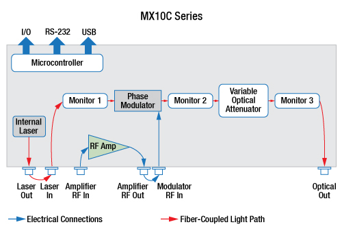 |
|
| MX10C-LB | 12.5 Gb/sa | L-Band, Tunable | |||||
| MX10C-1310 | 12.5 Gb/sa | 1310 nm, Fixed | |||||
| MX35E | 35 GHzb | C-Band, Tunable | Intensity | Linear | 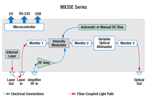 |
||
| MX35E-LB | 35 GHzb | L-Band, Tunable | |||||
| MX35E-1310 | 35 GHzb | 1310 nm, Fixed | |||||
| MX35D | 35 GHzb | C-Band, Tunable | Intensity | Linear with Differential Input |
 |
||
| MX35D-LB | 35 GHzb | L-Band, Tunable | |||||
| MX35D-1310 | 35 GHzb | 1310 nm, Fixed | |||||
| MX40B | 40 Gb/sa | C-Band, Tunable | Intensity | Digital | 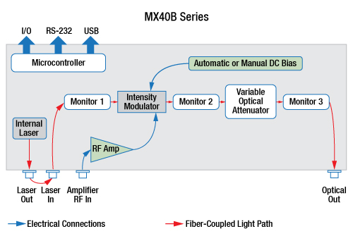 |
||
| MX40B-LB | 40 Gb/sa | L-Band, Tunable | |||||
| MX40B-1310 | 40 Gb/sa | 1310 nm, Fixed | |||||
| MX40C | 40 Gb/sa | C-Band, Tunable | Phase | Digital | - | 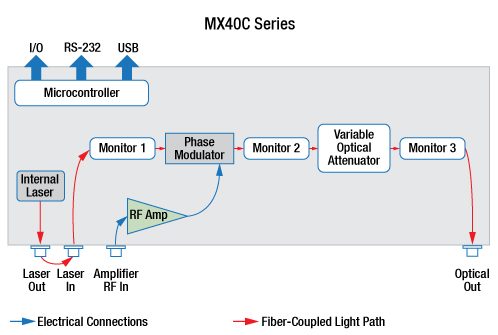 |
|
| MX40C-LB | 40 Gb/sa | L-Band, Tunable | |||||
| MX40C-1310 | 40 Gb/sa | 1310 nm, Fixed | |||||
| MX50E-850 | 50 GHzb | 852 nm, Fixed | Intensity | Linear | |||
| MX65E | 65 GHzb | C-Band, Tunable | Intensity | Linear |  |
||
| MX65E-LB | 65 GHzb | L-Band, Tunable | |||||
| MX65E-1310 | 65 GHzb | 1310 nm, Fixed | |||||
| E-O Converters for VNA Applications | |||||||
| MX40G | 40 GHzb | C-Band, Tunable | Intensity | - |  |
||
| MX40G-LB | 40 GHzb | L-Band, Tunable | |||||
| MX40G-850 | 40 GHzb | 850 nm, Fixed | |||||
| MX40G-1310 | 40 GHzb | 1310 nm, Fixed | |||||
| MX70G | 70 GHzb | C-Band, Tunable | Intensity | - | |||
| MX70G-LB | 70 GHzb | L-Band, Tunable | |||||
| MX70G-1310 | 70 GHzb | 1310 nm, Fixed | |||||
| MX70G-DB1 | 70 GHzb | C-Band, Tunable | Intensity | - |  |
||
| 1310 nm, Fixed | |||||||
| MX110G | 110 GHzb | C-Band, Tunable | Intensity | - | 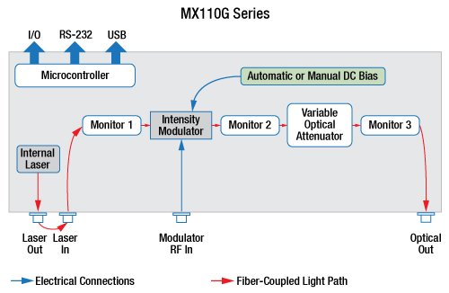 |
||
| MX110G-1310 | 110 GHzb | 1310 nm, Fixed | |||||
The capabilities of Thorlabs' extensive range of transmitter instruments are summarized in the text and table below. All members of this product series share a similar interface, as well as a common remote control command set.
Automatic Bias Controller
Thorlabs' fully-featured automatic bias controller provides complete and precise control of DC bias and optical output power for any fiber-coupled LiNbO3 EO intensity modulator, regardless of signal speed. Automatic bias controllers are ideal for use within a customized setup that uses an external laser, intensity modulator, signal source, and RF amplifier.
Tunable Telecom-Grade Laser Sources
Emitting in the C-band or the L-band, these lasers have narrow typical linewidths of 10 kHz. A frequency dither option aids in stabilizing the laser wavelength, and the integrated variable optical attenuator (VOA) provides optical output power control. These lasers are tunable in 50 GHz steps across the ITU frequency grid, and feature a 1 MHz step size fine-tune capability, as well.
High-Speed Modulator Drivers
With an operational wavelength range of 1250 nm to 1610 nm, each modulator driver provides control for an external fiber-coupled LiNbO3 EO modulator. Each modulator driver includes an RF amplifier with amplitude and eye-crossing controls and accepts an external drive signal source. Models with integrated automatic bias controllers are offered for use with intensity EO modulators.
High-Speed Optical Transmitters
Designed to provide fully-integrated solutions for high-speed light modulation, these systems are built around a LiNbO3 intensity or phase modulator. The MX10B, MX40B, MX10C, and MX40C series of systems include a digital (limiting) RF amplifier, which offers fixed gain and an adjustable output voltage swing. The MX35E, MX50E, and MX65E series include a high-bandwidth linear (analog) RF amplifier, making it well suited for pulse amplitude modulation and related applications.
E-O Converters for VNA Applications
With our MX40G, MX70G, and MX110G series of E-O converters, any E-E vector network analyzer can be used to perform optical testing up to 40 GHz, 70 GHz, and 110 GHz respectively. The E-O converter is a fully-integrated solution that includes a laser, a modulator, and bias control.
| Posted Comments: | |
| No Comments Posted |

 Zoom
Zoom| Key System Specificationsa | |||||
|---|---|---|---|---|---|
| Item # | MX40G-850 | MX40G-1310 | MX40G | MX40G-LB | |
| Frequency Responseb (Click for Plot) |
DC - 40 GHz | DC - 40 GHz | |||
| Internal Laser Type | Fixed Wavelength | C-Band, Tunable | L-Band, Tunable | ||
| Internal Laser Wavelength | 852 nm (Typ.) | 1310 nm (Typ.) | 1527.6 - 1565.5 nm | 1570.0 - 1608.8 nm | |
| External Laser Support | None | 1250 - 1610 nm, 20 dBm Max | |||
| Input RF Connector Type | 2.92 mm Connectorc | ||||
- For Applications up to 40 GHz
- Multiple Integrated Internal Laser Options:
- 852 nm Fixed Wavelength
- 1310 nm Fixed Wavelength
- C-Band Tunable on ITU 50 GHz Grid
- L-Band Tunable on ITU 50 GHz Grid
- Operation from 1250 to 1610 nm with User-Supplied External Laser (Excluding MX40G-850 Converter)
The MX40G Series E-O Converters can operate up to 40 GHz and include an external loop-back cable for connecting the internal laser output to the modulator input (except the MX40G-850 converter).

 Zoom
Zoom| Key System Specificationsa | |||||
|---|---|---|---|---|---|
| Item # | MX70G-1310 | MX70G | MX70G-LB | MX70G-DB1 | |
| Frequency Responseb (Click for Plot) |
DC - 70 GHz | ||||
| Internal Laser Type | Fixed Wavelength | C-Band, Tunable | L-Band, Tunable |
Fixed Wavelength | C-Band, Tunable |
| Internal Laser Wavelength | 1310 nm | 1527.6 - 1565.5 nm | 1570.0 - 1608.8 nm | 1310 nm | 1527.6 - 1565.5 nm |
| External Laser Support | 1250 - 1610 nm, 20 dBm Max | ||||
| Input RF Connector Type | 1.85 mm Connectorc | ||||
- For Applications up to 70 GHz
- Single Integrated Internal Laser Options:
- 1310 nm Fixed Wavelength
- C-Band Tunable on ITU 50 GHz Grid
- L-Band Tunable on ITU 50 GHz Grid
- Dual Integrated Laser Option:
- 1310 nm Fixed Wavelength and C-Band Tunable on ITU 50 GHz Grid
- Operation from 1250 to 1610 nm with
User-Supplied External Laser
The MX70G Series E-O Converters can operate up to 70 GHz and include an external loop-back cable for connecting the internal laser output to the modulator input.
In addition to single-laser options, the MX70G Series also includes the MX70G-DB1 dual- band E-O converter. This unit integrates both a 1310 nm fixed wavelength laser and a C-Band tunable laser, making it ideal for multi-wavelength testing applications.

 Zoom
Zoom
| Key System Specificationsa | |||||
|---|---|---|---|---|---|
| Item # | MX110G-1310 | MX110G | |||
| Frequency Responseb (Click for Plot) |
DC - 110 GHz | ||||
| Internal Laser Type | Fixed Wavelength | C-Band, Tunable | |||
| Internal Laser Wavelength | 1310 nm | 1527.6 - 1565.5 nm | |||
| External Laser Support | 1260 - 1360 nm, 17 dBm Max | 1525 - 1575 nm, 17 dBm Max | |||
| Input RF Connector Type | 1.0 mm Connectorc | ||||
- For Applications up to 110 GHz
- Single Integrated Internal Laser Options:
- 1310 nm Fixed Wavelength
- C-Band Tunable on ITU 50 GHz Grid
- Wavelength Range for User-Supplied External Laser:
- MX110G-1310: 1260 to 1360 nm
- MX110G: 1525 to 1575 nm
The MX110G Series E-O Converters can operate up to 110 GHz and include an external loop-back cable for connecting the internal laser output to the modulator input.