 Products Home / Optomechanical Components / Optomechanical Mounts / Optical Mirror Mounts / Polaris® Mirror Mounts / Polaris® Fixed Optic Mounts
Polaris® Fixed Optic Mounts

- Monolithic Design for Minimal Optic Distortion
- Heat Treating Minimizes Temperature-Dependent Hysteresis
- Versions Optimized for Lenses, Mirrors, and Beamsplitters
- Models Available for Ø1/2", Ø1", and Ø2" Optics
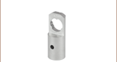
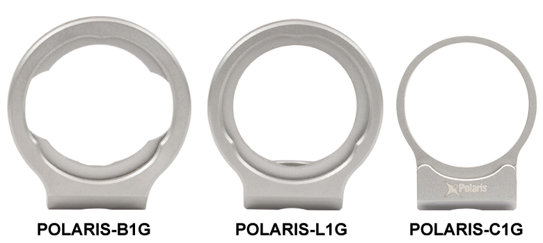
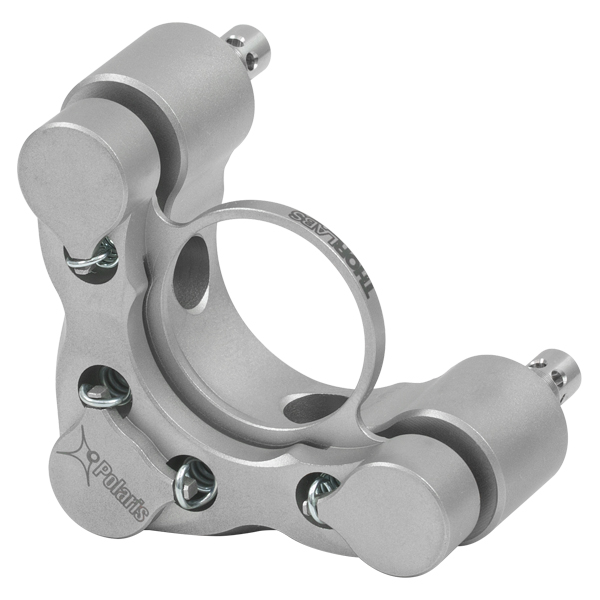
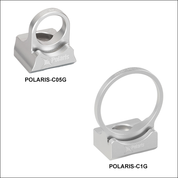
POLARIS-L1G
Ø1" Glue-In Lens Mount
(Ø1/2" Also Available)
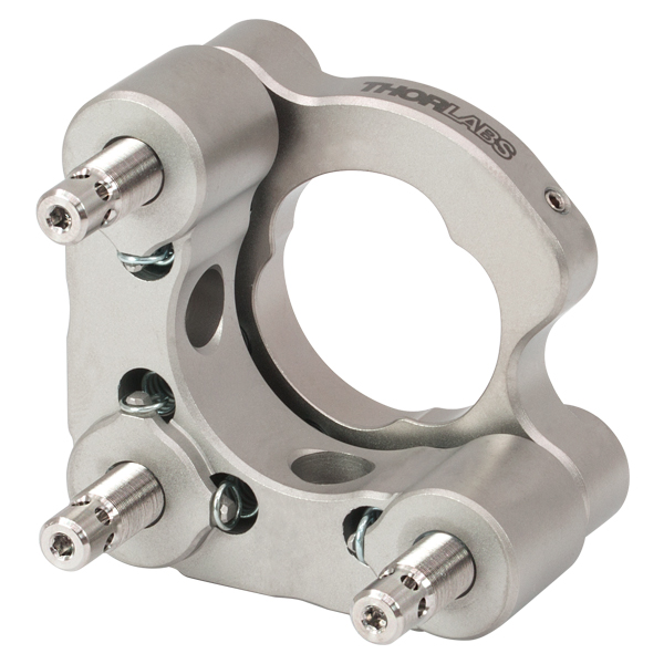
POLARIS-C1G
Ø1" Glue-In Mirror Mount
(Ø1/2" and Ø2" Also Available)
POLARIS-B1G
Ø1" Glue-In Beamsplitter Mount
(Ø1/2" Also Available)
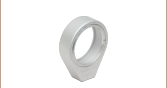
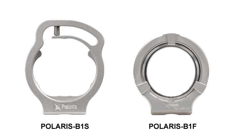
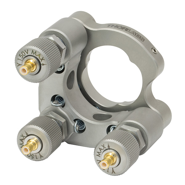
POLARIS-B1S
Ø1" Flexure-Clamp
Beamsplitter Mount
(Ø1/2" and Ø2" Also Available)
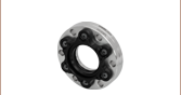
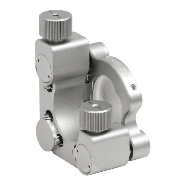
POLARIS-B1F
Ø1" Low-Distortion
Mirror Mount
(Ø1/2" and Ø2" Also Available)


Please Wait
Mounts for OEMs
Thorlabs' Polaris Fixed Optic Mounts were designed to meet the needs of OEM customers. To that end, we are equipped to manufacture these mounts in high volumes and with timed delivery. Additionally, we can design and manufacture modified versions of these mounts for mounting additional optic types, sizes, and shapes. For example, we have produced similar fixed mounts for square mirrors, diffraction gratings, different optic sizes, or different beam heights. To find out more about our OEM capabilities, please contact Tech Support.
| Quick Links |
|---|
| Glue-In Mounts |
| Lens-Optimized Mounts |
| Beamsplitter-Optimized Mounts |
| Mirror-Optimized Mounts |
| Flexure Clamp, Beamsplitter-Optimized Mounts |
| Low-Distortion, Mirror-Optimized Mounts |
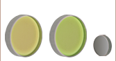
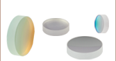
Click to Enlarge
The three Polaris glue-in fixed mount designs: optimized for beamsplitters (left), optimized for lenses (middle), and optimized for mirrors (right). The Ø1" versions are shown here.
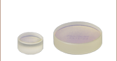
Click to Enlarge
The Polaris flexure-clamp fixed mount design (left) is optimized for beamsplitters The low-distortion design (right) is optimized for mirrors. The Ø1" versions are shown here.
Features
- Fixed Mounts Machined from Heat-Treated Stainless Steel with Low Coefficient of Thermal Expansion (CTE)
- Optimized for Three Different Optic Types and Diameters (See Table to the Right for Details)
- Glue-In Mount Options:
- Lens-Optimized with Coarse Focus Adjustment (Ø1/2" or Ø1")
- Beamsplitter-Optimized with Increased Transmissive Clear Aperture (Ø1/2" or Ø1")
- Mirror-Optimized with Clear Edge (Ø1/2", Ø1", or Ø2")
- Flexure Clamp Mounts with Large Transmissive Clear Aperture for Use with Beamsplitters (Ø1/2", Ø1", or Ø2")
- Low-Distortion Mounts Ideal for Use with Mirrors (Ø1/2", Ø1", or Ø2")
- Extensive Testing Guarantees <2 μrad Deviation After 10 °C Temperature Cycling (See the Test Data Tab for Details)
- Passivated Stainless Steel Surface Ideal for Vacuum and High-Power Laser Cavity Applications
Polaris® Fixed Optic Mounts are the ultimate solution for applications requiring stringent long-term alignment stability. Fixed mounts for plano or curved, Ø1/2", Ø1", or Ø2" optics are available below. The mounts are optimized for either lenses, beamsplitters, or mirrors.
Optic Mounting
Polaris Glue-In Optic Mounts feature a mounting cell in which an optic can be permanently affixed with an optical adhesive (available below). This mounting technique results in significantly less optical surface distortion than traditional methods based on setscrews or flexure mechanisms. See the Optic Installation tab for more information on installing optics in the glue-in mounts. The glue-in mounts on this page can be used with metric-sized optics; however, the optic locating points will not center the optic, requiring the centration to be adjusted by hand during installation. The mounts should not be used with optics that have an outer diameter tolerance greater than zero.
Polaris Flexure-Clamp Optic Mounts provide highly stable mounting without permanently affixing the optic. A monolithic stainless steel flexure clamp and setscrew combination provides temperature-independent retention of the optic with maximum stability and low wavefront distortion. The mounts are designed for optics with imperial diameters; performance will be diminished if these mounts are used with optics with metric diameters. For custom mounts sized for metric optics, please contact Tech Support.
Polaris Low-Distortion Optic Mounts (US Patent 9,599,786) provide long-term pointing stability while minimizing optic surface distortion introduced by the mount. Each mount features a three-point-contact faceplate to mount the optic to reduce optical distortion compared to standard setscrew or retaining ring optic mount designs. An indexed retention spring between the optic and retaining ring eliminates bending moments on the optic and ensures the force on the optic remains constant over large temperature changes. See the Test Data and Optic Installation tabs for more details. The Ø1/2" mount can be used with Ø12.5 mm optics, while the Ø1" and Ø2" mounts are designed for optics with imperial diameters; performance will be diminished if these mounts are used with optics with metric diameters. For inquiries about mounts for other optic sizes, please contact Tech Support.
Design
As shown on the Test Data and Design Features tabs, these Polaris mounts have been extensively developed and tested to ensure high-quality performance by using the proper materials, components, and dimensional specifications. The Polaris design addresses all of the common causes of beam misalignment.
Post Mounting
The Polaris fixed optic mounts are equipped with #8 (M4) counterbores for post mounting. The mounts also feature Ø2 mm alignment pin holes around the mounting counterbore, allowing for precision alignment when paired with our Ø1" Posts for Polaris Mounts. See the Usage Tips tab for more recommendations on mounting configurations.
Cleanroom and Vacuum Compatibility
All Polaris mounts sold on this page are designed to be compatible with cleanroom and vacuum chamber applications. Please see the Specs tab and the Design Features tab for more information on vacuum compatibility.
| Glue-In Mounts | |||||||
|---|---|---|---|---|---|---|---|
| Item # Suffixa | -L05G | -L1G | -B05G | -B1G | -C05G | -C1G | -C2G |
| Recommended Optic Type | Lens | Beamsplitter | Mirror | ||||
| Optic Sizeb | Ø1/2" | Ø1" | Ø1/2" | Ø1" | Ø1/2" | Ø1" | Ø2" |
| Transmissive Clear Aperture | Ø0.39" (Ø10.0 mm) | Ø0.88" (Ø22.3 mm) | Ø0.39" (Ø10.0 mm) | Ø0.88" (Ø22.3 mm) | Ø0.39" (Ø10.0 mm) | Ø0.88" (Ø22.3 mm) | Ø1.80" (Ø45.7 mm) |
| Beam Deviation After Thermal Cycling |
<1 μradc | <2 µradd | |||||
| Recommended Optic Mounting Adhesivee |
Norland Optical Adhesive 61 (NOA61, Sold Below) or EPO-TEK 301-2FL Low-Stress Optical Epoxy |
||||||
| Mountingf | #8 (M4) Counterbored Slot, 0.22" (5.6 mm) Adjustment Range |
#8 (M4) Counterbored Hole | Three #8 (M4) Counterbored Holes |
||||
| Alignment Pin Holes | Two Ø2 mm Holes for DIN 7-m6 Ground Dowel Pin on Either Side of Center Counterbore | ||||||
| Vacuum Compatibilityg | 10-9 Torr at 25 °C with Proper Bake Out; 10-5 Torr at 25 °C without Bake Out | ||||||
| Operating Temperature | -30 to 200 °C | ||||||
| Flexure Clamp Mounts | |||
|---|---|---|---|
| Item # Suffixa | -B05S | -B1S | -B2S |
| Recommended Optic Type | Beamsplitter | ||
| Optic Sizeb | Ø1/2" | Ø1" | Ø2" |
| Optic Thickness (Min) | 0.12" (3.0 mm) | 0.15" (3.8 mm) | |
| Transmissive Clear Aperture | Ø0.45" (Ø11.4 mm)c | Ø0.90" (Ø22.9 mm) | Ø1.80" (Ø45.7 mm) |
| Beam Deviation After Thermal Cycling | <1 μradd | ||
| Recommended Optic Mounting Torquee | 2 - 3 oz-in | 2 - 4 oz- |
6 - 8 oz-in |
| Mountingf | #8 (M4) Counterbored Hole | Three #8 (M4) Counterbored Holes | |
| Alignment Pin Holes | Two Ø2 mm Holes for DIN 7-m6 Ground Dowel Pin at Each Counterbore | ||
| Vacuum Compatibilityg | 10-9 Torr at 25 °C with Proper Bake Out; 10-5 Torr at 25 °C without Bake Out | ||
| Operating Temperature | -30 to 200 °C | ||
| Low-Distortion Mounts | ||||
|---|---|---|---|---|
| Item # Suffixa | -B05F | -B1F | -B2F | |
| Recommended Optic Type | Mirror | |||
| Optic Sizeb | Ø1/2" or Ø12.5 mm | Ø1" | Ø2" | |
| Optic Thickness | Min | 0.09" (2.3 mm) | 0.15" (3.8 mm) | 0.12" (3.0 mm) |
| Max | 0.28" (7.0 mm)c 0.33" (8.5 mm)d |
0.32" (8.0 mm)c 0.38" (9.7 mm)e |
0.525" (13.3 mm)c 0.55" (13.9 mm)f |
|
| Transmissive Clear Aperture | Ø0.36" (Ø9.1 mm)c Ø0.43" (Ø10.9 mm)d |
Ø0.83" (Ø21.0 mm)c Ø0.90" (Ø22.8 mm)e |
Ø1.73" (Ø43.9 mm)c Ø1.90" (Ø48.2 mm)f |
|
| Beam Deviation After Thermal Cycling | <2 μradg | |||
| Recommended Optic Mounting Turns Backh | 1/2 Turn | 1.25 Turns | 1.25 Turns | |
| Mountingi | #8 (M4) Counterbored Hole | Three #8 (M4) Counterbored Holes | ||
| Alignment Pin Holes | Two Ø2 mm Holes for DIN 7-m6 Ground Dowel Pin on Either Side of Center Counterbore | |||
| Vacuum Compatibilityj | 10-9 Torr at 25 °C with Proper Bake Out; 10-5 Torr at 25 °C without Bake Out | |||
| Operating Temperature | -30 to 200 °C | |||
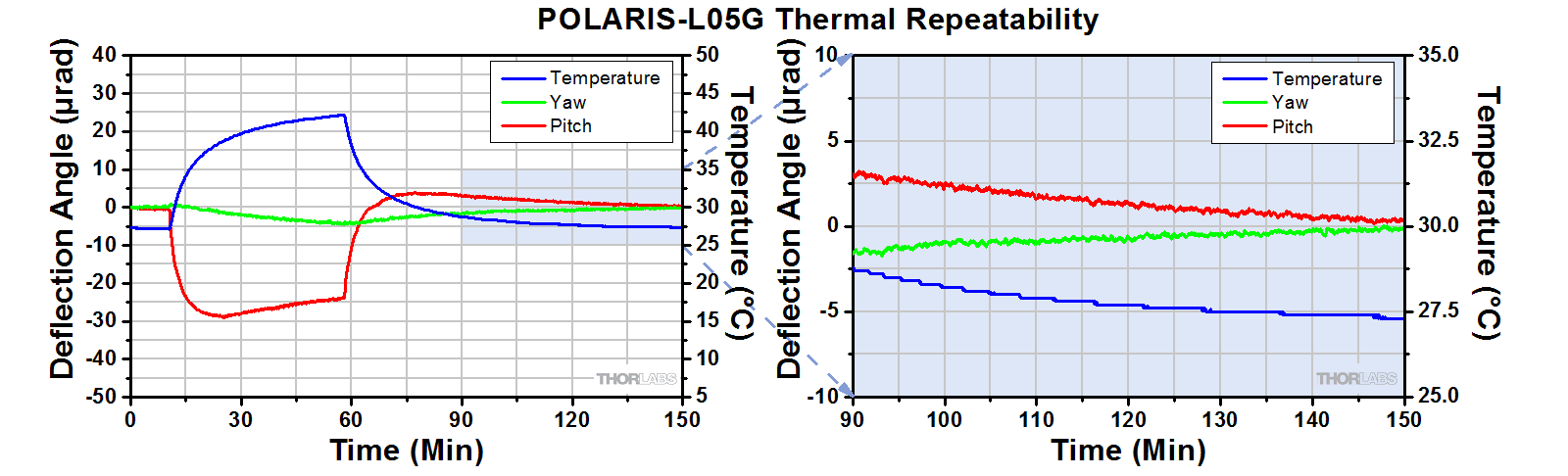
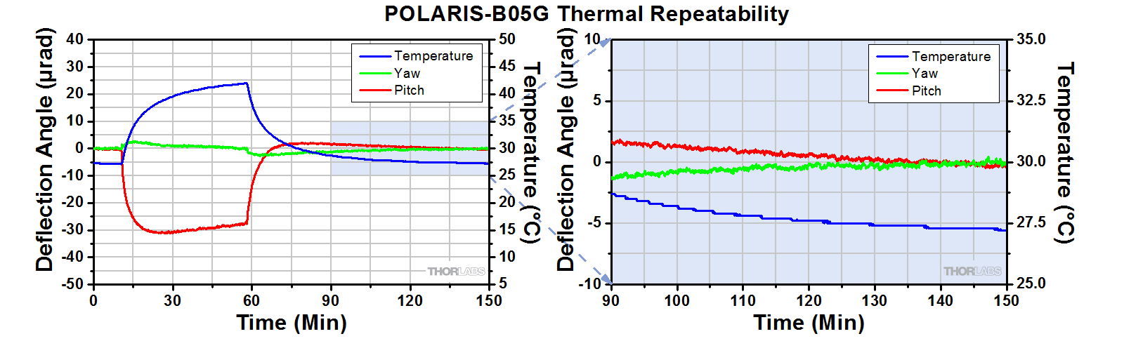
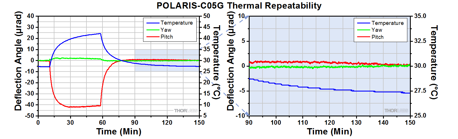
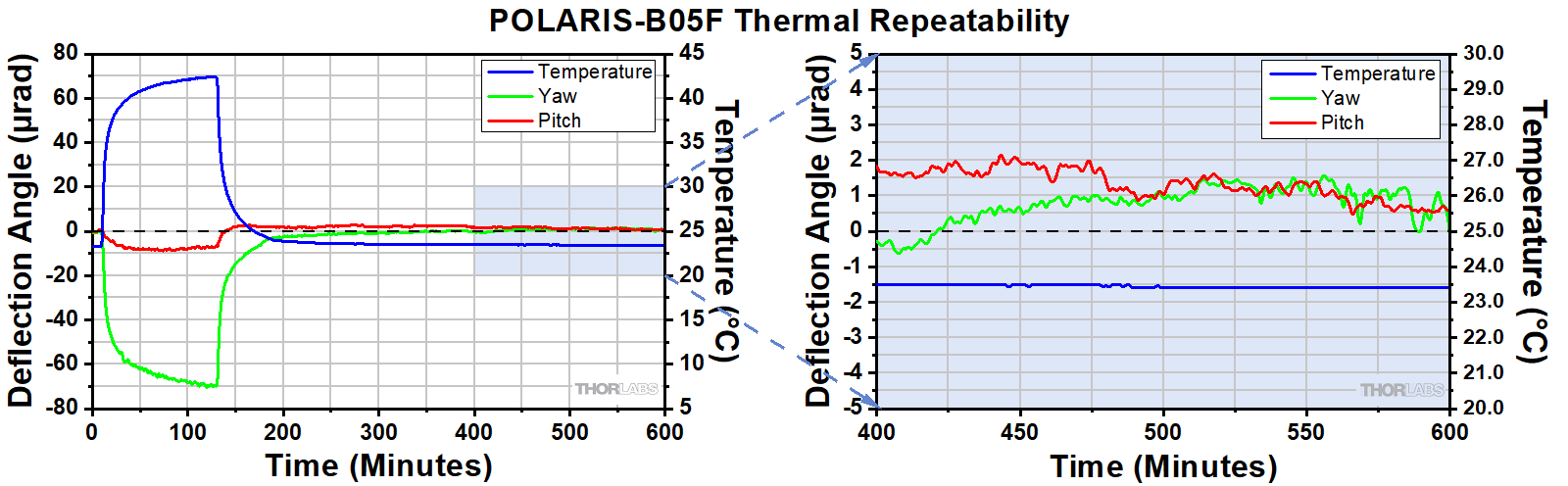
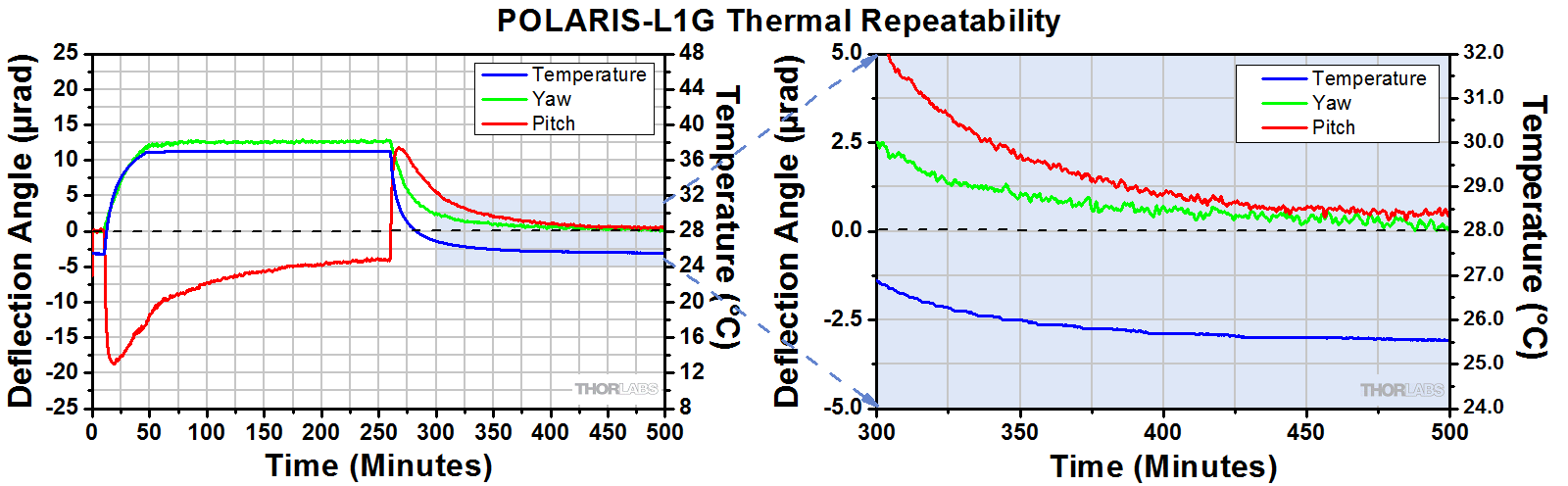
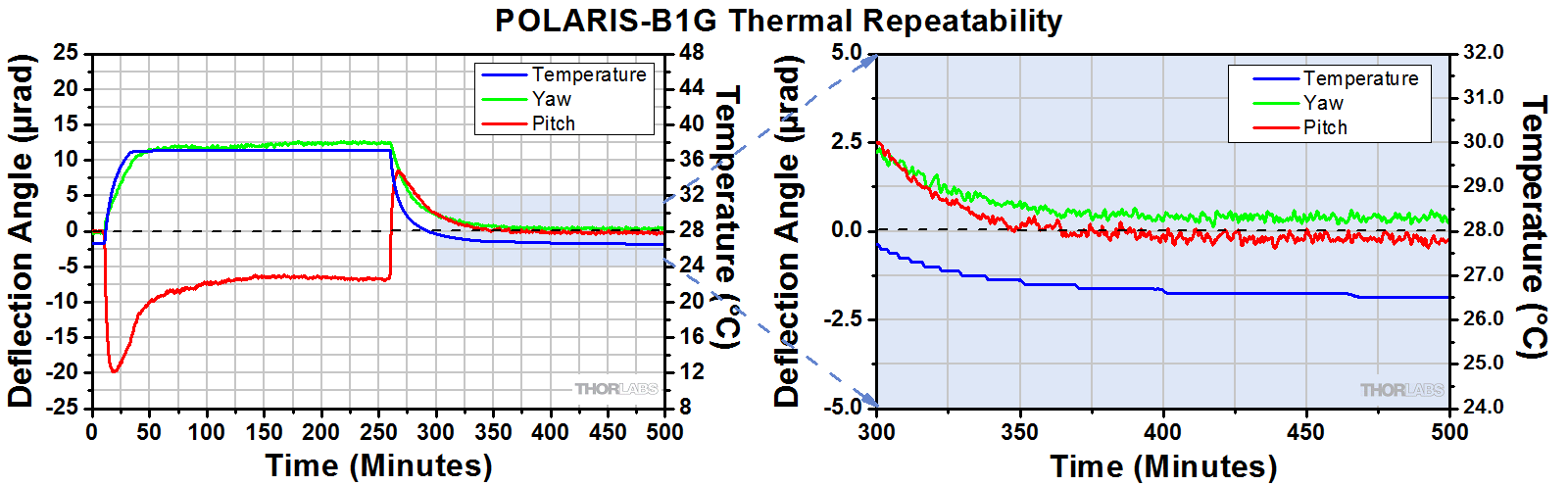
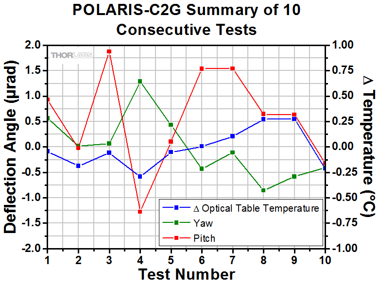
Positional Repeatability After Thermal Shock
This testing was done to determine how reliably the mount returns the mirror, without hysteresis, to its initial position so that the alignment of the optical system is unaffected by the temperature shock. During the testing phase, the Polaris mounts were attached to a PLS-P150 Ø1" Post and secured to a stainless steel optical breadboard using a POLARIS-CA1 clamping arm in a temperature-controlled environment. Each mount was secured to the post by an 8-32 cap screw with 16 in-lb of torque. The mirrors were installed in the mounts following the recommended mounting procedures. The beam from an independently temperature-stabilized diode laser was reflected off the mirror's surface onto a position sensing detector.
Procedure:
For these tests, a mirror was used in all mounts, regardless of the mount style. The temperature of each mount tested was raised by at least 10 °C. The elevated temperature was maintained in order to soak the mount at a constant ambient temperature. Then the temperature of the mount was returned to the starting temperature. The results of these tests are shown below.
Results:
The maximum beam deviation of each mount depends on the magnitude of the thermal shock applied to it. However, when the Polaris fixed optic mounts were returned to the initial temperature, the angular position (both pitch and yaw) of the mirrors returned to within 1 µrad of the initial position (within 2 µrad for Item #s POLARIS-C2G, POLARIS-B05F, POLARIS-B1F, and POLARIS-B2F). Expand the tables below to see plots showing this data.
For Comparison:
To get a 1 µrad change in the mount's position, the 100 TPI adjuster on the POLARIS-K1F kinematic mount needs to be rotated by only 0.05° (1/7200 of a turn). A highly skilled operator might be able to make an adjustment as small as 0.3° (1/1200 of a turn), which corresponds to 6 µrad.
| Ø1/2" Polaris Mirror Mounts Thermal Shock Data |
|---|


| Ø1" Polaris Mirror Mounts Thermal Shock Data |
|---|
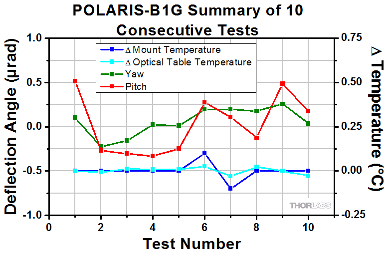


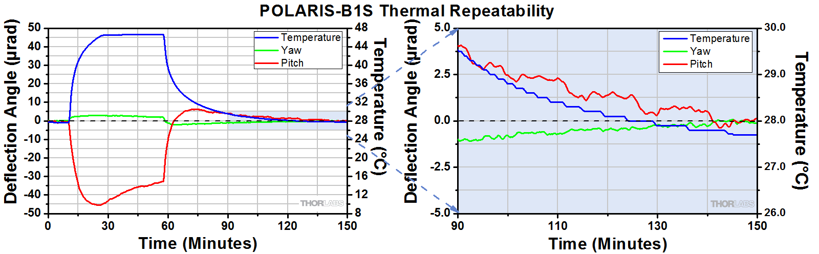
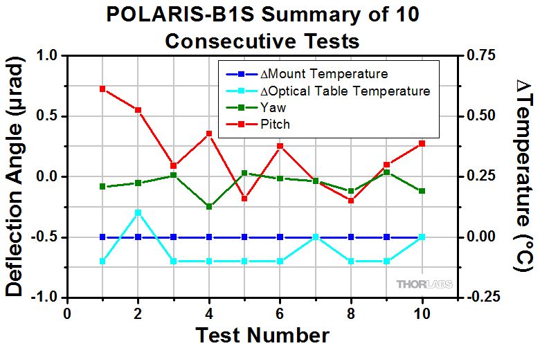

| Ø2" Polaris Mirror Mounts Thermal Shock Data |
|---|


Click to Enlarge
Preparing a Polaris fixed optic mount for testing with our ZYGO Interferometer.
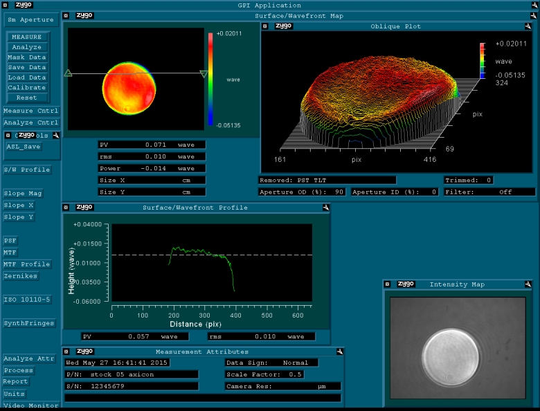
Optical Distortion Testing Using a ZYGO Phase-Shifting Interferometer
Mounting stresses are responsible for the strain that results in optical surface distortion. Minimizing distortion effects is crucial; any distortion of the optic affects the reflected wavefront. Polaris fixed optic mounts offer maximum stability while minimizing optic distortion for applications like laser cavity construction.
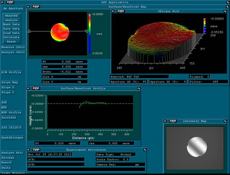
Glue-In Mounts
To determine the amount of optic distortion caused by the adhesive mounting process in our fixed glue-in mounts, a ZYGO Phase-Shifting Interferometer was used to measure the wavefront reflected from both unmounted and mounted mirrors (for testing purposes, a mirror was used in all three mounts). Based on results of the test, we can conclude that our glue-in Polaris mounts introduce a minimum amount of wavefront distortion.
Procedure:
A broadband dielectric mirror was loosely placed on a POLARIS-C1G mount without any adhesive. Measurements of the optic distortion were then recorded using the ZYGO interferometer. The mirror was then bonded to a POLARIS-C1G Ø1" mount using UV-curing Norland Optical Adhesive 61 (Item # NOA61, available below). Additional Zygo measurements of the fixed optic were then recorded to determine the amount of distortion induced by the mounting process. The remaining glue-in mounts were also tested with the optic bonded to the mount.
Results:
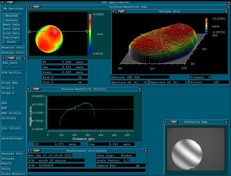
As shown in the images below, the surface of the mounted optic exhibited very little distortion. This result indicates that the optic mounting procedure results in virtually no change to the optical surface. Therefore, the Polaris fixed optic mounts are ideal for demanding applications that are sensitive to wavefront distortions.
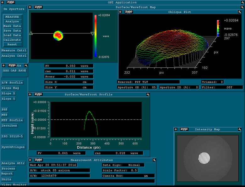
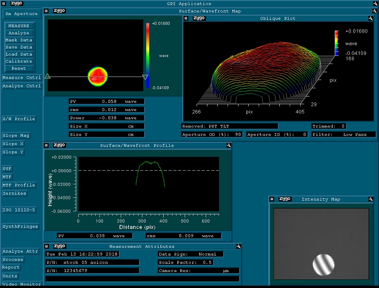
Fixed Optic in POLARIS-C05G
Click to Enlarge
Optical Surface Distortion of a Mirror Fixed in a
POLARIS-C05G Ø1/2" Mount with NOA61 Optical Adhesive
Fixed Optic in POLARIS-L05G

Click to Enlarge
Optical Surface Distortion of a Mirror Fixed in a
POLARIS-L05G Ø1/2" Mount with NOA61 Optical Adhesive
Fixed Optic in POLARIS-B05G
Click to Enlarge
Optical Surface Distortion of a Mirror Fixed in a
POLARIS-B05G Ø1/2" Mount with NOA61 Optical Adhesive
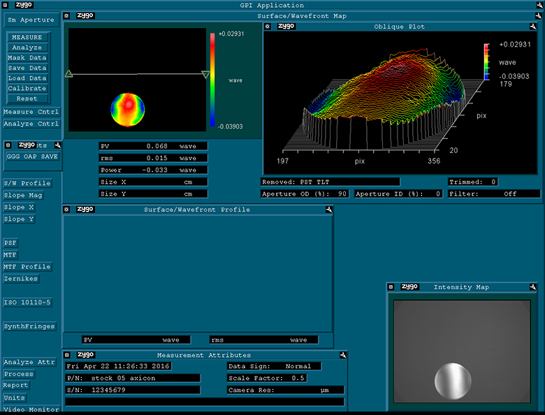
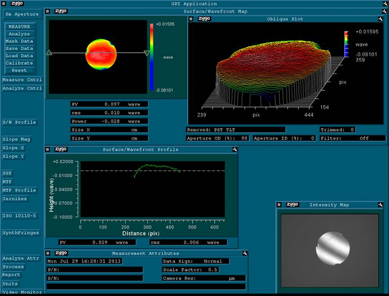
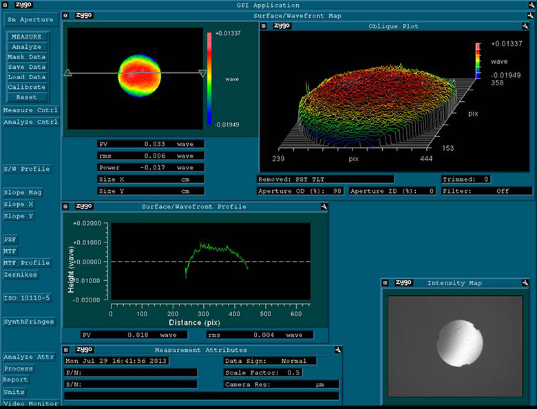
Loose Optic in POLARIS-C1G
Click to Enlarge
Optical Surface Distortion of a Loose Mirror Placed on a POLARIS-C1G Mount
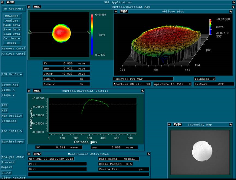
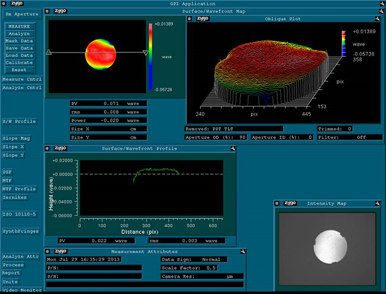
Fixed Optic in POLARIS-C1G

Click to Enlarge
Optical Surface Distortion of a Mirror Fixed in a
POLARIS-C1G Ø1" Mount with NOA61 Optical Adhesive
Fixed Optic in POLARIS-L1G
Click to Enlarge
Optical Surface Distortion of a Mirror Fixed in a
POLARIS-L1G Ø1" Mount with NOA61 Optical Adhesive
Fixed Optic in POLARIS-B1G

Click to Enlarge
Optical Surface Distortion of a Mirror Fixed in a
POLARIS-B1G Ø1" Mount with NOA61 Optical Adhesive
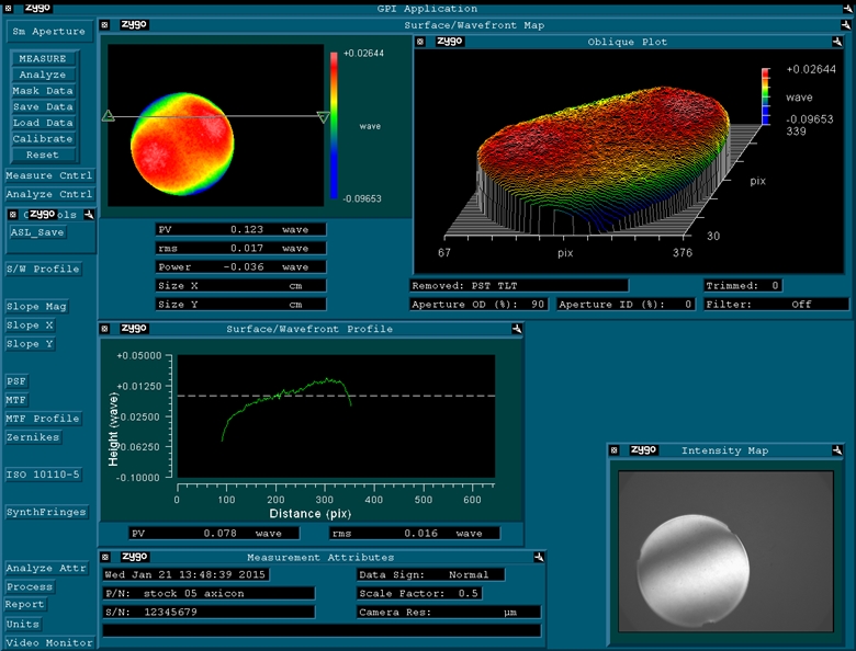
Fixed Optic in POLARIS-C2G
Click to Enlarge
Optical Surface Distortion of a Mirror Fixed in a
POLARIS-C2G Ø2" Mount with NOA61 Optical Adhesive
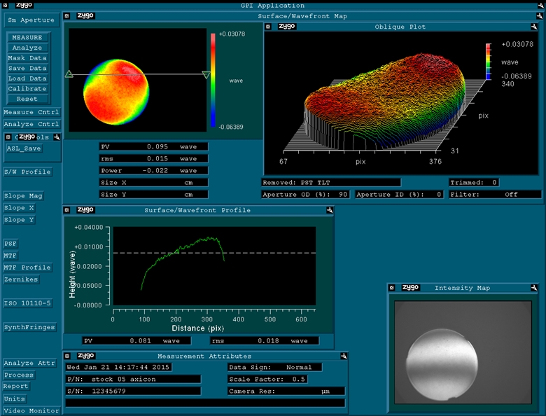
Flexure-Clamp Mounts
To determine the amount of optic distortion exerted on the mirror by the flexure arm, a ZYGO Phase-Shifting Interferometer was used to measure the wavefront distortion at different torque values (see the image below). Based on results of the tests seen below, we recommend a torque of 2 - 3 oz-in for our Ø1/2" flexure-clamp fixed mount, at which the optic wavefront distortion is ≤0.1λ. We recommend a torque of 2 - 4 oz-in to obtain a wavefront distortion of ≤0.1λ for optics in our Ø1" flexure-clamp fixed mount, and a torque of 6 - 8 oz-in to obtain a wavefront distortion of which was tested ≤0.1λ for optics in our Ø2" flexure-clamp fixed mount, using the same method.
Procedure:
A broadband dielectric mirror was installed into a Polaris mount using the setscrew to clamp down the flexure arm. Measurements of the optic distortion were then recorded using the ZYGO interferometer. Once each measurement was complete, the amount of force needed to push the optic out of the mount was measured to check optic retention. The wavefront distortion values shown here give peak-to-valley distortion across the entire optic, representing the worst-case scenario; the center of the optic exhibits significantly less distortion than the edge.
Results:
As shown in the images below, the surface of the mounted optic exhibited very little distortion. This result indicates that the optic mounting procedure results in virtually no change to the optical surface. Therefore, the Polaris fixed optic mounts are ideal for demanding applications that are sensitive to wavefront distortions.

Click to Enlarge
POLARIS-B05S Wavefront Distortion for Setscrew Torque of 3 oz-in (See Table to the Right for Other Torque Values)

Click to Enlarge
POLARIS-B2S Wavefront Distortion for Setscrew Torque of 6 oz-in
| POLARIS-B05S Wavefront Distortion | ||
|---|---|---|
| Torque (oz-in)a |
Push-Out Force (lbf)b |
Wavefront Distortion (Peak to Valley)c |
| 1.5 | >12 | 0.036λ to 0.052λ |
| 2 | 0.045λ to 0.083λ | |
| 2.5 | 0.077λ to 0.097λ | |
| 3 | 0.089λ to 0.100λ | |
| 3.5 | 0.118λ to 0.137λ | |
| 4 | 0.131λ to 0.185λ | |
| POLARIS-B1F & POLARIS-B2F Wavefront Distortiona | ||
|---|---|---|
| # of Turns Back the Retaining Ring was Loosenedb |
Wavefront Distortion (Peak to Valley)c | |
| -B1F | -B2Fd | |
| 1/4 Turn | 0.097λ | 0.123λ to 0.133λ |
| 1/2 Turn | 0.090λ | 0.122λ to 0.124λ |
| 3/4 Turn | 0.083λ | 0.111λ to 0.116λ |
| 1 Turn | 0.081λ | 0.100λ to 0.106λ |
| 1.25 Turns | 0.071λ | 0.094λ to 0.098λ |
| 1.5 Turns | 0.062λ | 0.095λ to 0.099λ |
| 1.75 Turns | 0.053λ | 0.086λ to 0.094λ |
| 2 Turns | 0.033λ | 0.082λ to 0.089λ |

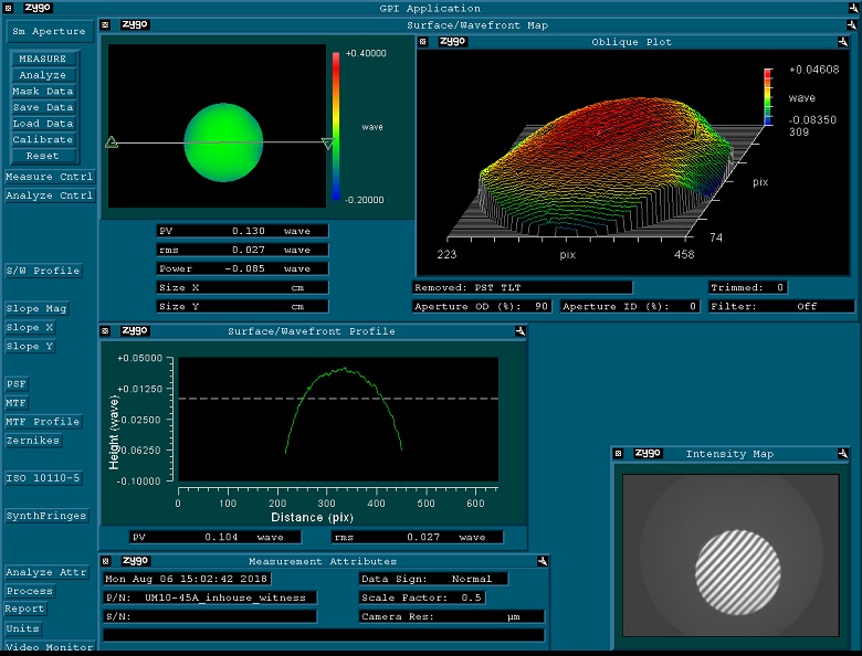
Click to Enlarge
POLARIS-K05F6 wavefront distortion with retaining ring turned back a 1/2 turn. We recommend the same procedure for the POLARIS-B05F Mount.
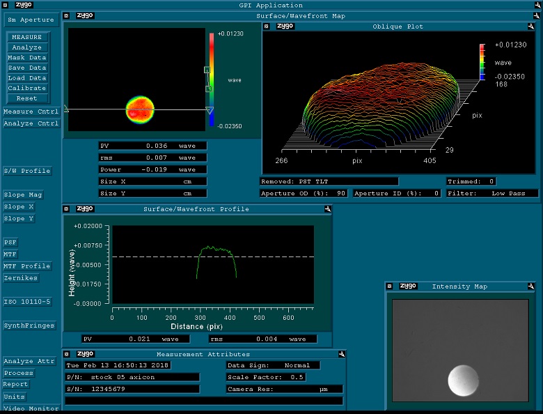
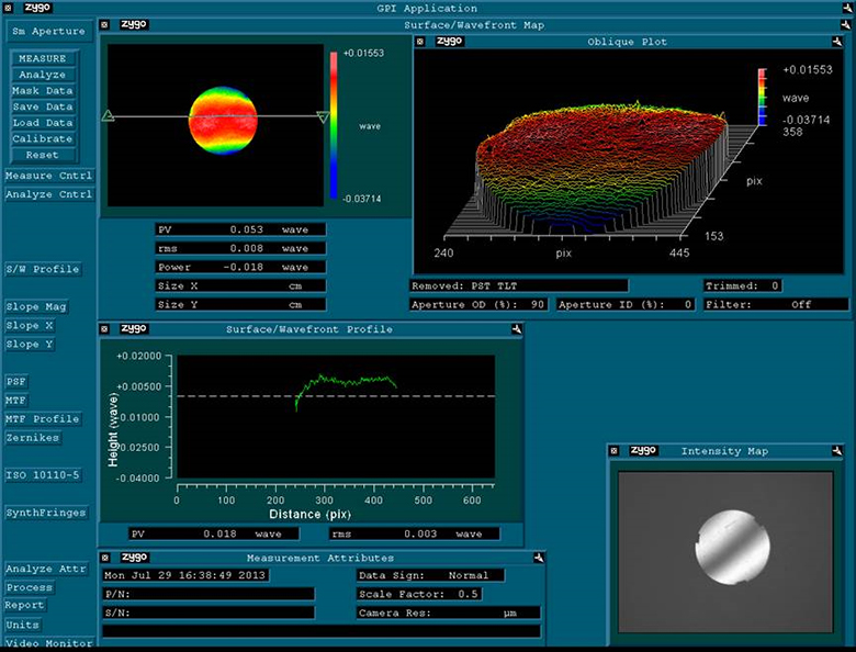
Low-Distortion Mounts
To determine the amount of optic distortion exerted on the mirror by the retaining ring, wave spring, and three contact points, a ZYGO Phase-Shifting Interferometer was used to measure the wavefront reflected from both unmounted and mounted mirrors. Based on results of the test, we can conclude that our low-distortion Polaris mounts introduce a minimal amount of wavefront distortion.
Procedure
For each test, a fused silica broadband dielectric mirror was installed into a Polaris low-distortion kinematic mirror mount using the procedures detailed on the Low Distortion tab; that is, the retaining ring was tightened until the spring was fully compressed, and then the retaining ring was loosened incrementally. The mount was then secured to a Ø1" stainless steel post using an 8-32 cap screw tightened to a torque of 16 in-lb. A ZYGO Phase-Shifting Interferometer was then used to perform wavefront distortion measurements with its aperture outer diameter set to 80% for the Ø1/2" mount and 90% for the Ø1" and Ø2" mounts. The optic cells of the Ø1/2", Ø1", and Ø2" low-distortion fixed mounts sold below have the same designs as the Ø1/2", Ø1", and Ø2" kinematic low-distortion mounts, respectively, and therefore will provide similar performance.
Results
As seen in the image and the table to the right, the wavefront distortion was found to remain at or below 0.1λ for the Ø1/2" and Ø1" mounts and 0.133λ for the Ø2" mount.
Optic Installation Procedure for a Polaris Glue-In Mirror Mount Using a UV-Curing Adhesive

Click to Enlarge
The glue plane is highlighted for each style of glue-in mount above.
Installing an Optic into a Polaris® Glue-In Mirror Mount
Ensure that there is no grease, dirt, or dust on the optic mounting plane or on the optic itself. Polaris mounts are thoroughly cleaned and then sealed inside two vacuum bag layers to ensure the mounts are free of any contaminants when the package is first opened. If the mount has been handled at all prior to installing the optic, remove any particulates with clean, compressed air and/or clean the mount with acetone or methanol.
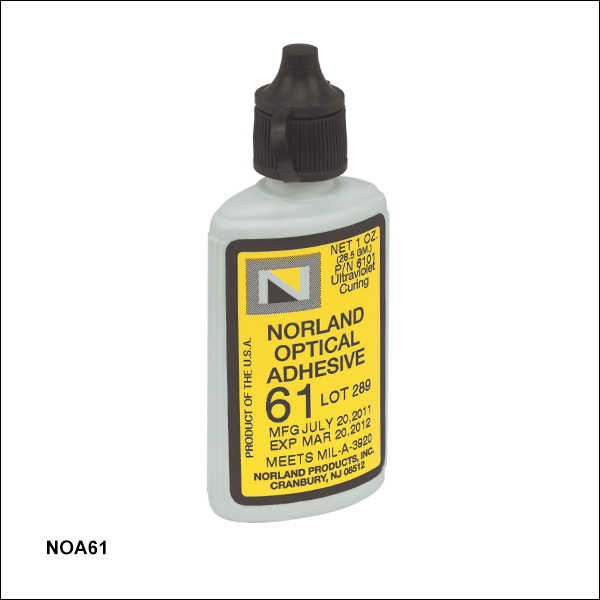
Using a clean stainless steel applicator or a syringe, apply a thin coating of optical adhesive to the entire optic glue plane (see photo to the right) in the area where the back surface of the optic will make contact. We recommend Norland Optical Adhesive 61 (item # NOA61, available below).
Then, slide the optic down the optic rim contact points until the back surface of the optic makes contact with the glue. The adhesive can then be cured with a UV curing LED system.
Optical Adhesives: We recommend Norland Optical Adhesive 61 (item # NOA61, available below) because of its ease of use. A 10-second pre-cure and a 10-minute final cure provides 3000 psi tensile strength, and the adhesive will maintain its performance over a wide temperature range of -150 °C to +125 °C. We also recommend EPO-TEK 301-2FL for operating temperatures up to 250 °C, at the cost of a slightly weaker bond than the NOA61. Other adhesives may be suitable depending on your application; contact Tech Support for assistance in choosing the appropriate one.
Single Plane Glue Bond: In order to minimize wavefront distortion, the adhesive layer should be confined to a single plane and should not contact the side of the optic. Polaris glue-in mounts offer relief cuts in the glue plane, allowing excess adhesive to flow away from the optic rather than onto the edges. The single plane bond prevents pockets or voids in the glue that reduce the bonding area and weaken the bond. Such pockets or voids are also more susceptible to misalignment due to fluctuations in temperature. In addition, allowing the glue to bond only to the back surface of the optic significantly reduces stress on the optic after the glue is cured.
Temperature while Curing: The temperature of the mount during the UV curing process should be controlled. UV ovens that significantly heat the mount should be avoided because the heat will cause thermal expansion of the mount, adhesive, and optic. Upon cooling, some residual stress will then develop in the glue bond and distort the optic.
See the Test Data tab for details on the low optic distortion provided by these mounts.
| Compatible Spannersa | ||
|---|---|---|
| Mount Size |
Spanner Wrench | Spanner Bitb |
| Ø1/2" | SPW603 or SPW603L | SPB05 |
| Ø1" | SPW606 or SPW602 | SPB1 |
| Ø2" | SPW604 | -c |
Installing an Optic into a Polaris Low-Distortion Fixed Mount
Ensure that there is no grease, dirt, or dust in the optic bore or on the optic itself. Remove any particulates with clean compressed air and/or clean with methanol, acetone, or ethanol. The optic, indexed retention spring, and retaining ring are installed from the back of the mount, as shown in the animation to the right. Be sure the index tab is in the key way and touching the retaining ring, otherwise there will be greater distortion of the optic. Gently turn the retaining ring using a spanner wrench (refer to table to the right for compatibility) until the optic makes contact with the three fingers on the faceplate. Note that at this point the retaining ring is about two turns away from compressing the wave spring and contacting the optic.
Securing an Optic by Turning Back the Retaining Ring (Recommended)
Continue to tighten until the spring is fully compressed into the pocket of the retaining ring, at which point the retaining ring will make slight contact with the back of the optic. Loosen the retaining ring by half a turn for the Ø1/2" mount or by 1.25 turns for the Ø1" and Ø2" mounts so that the spring pressure alone holds the optic in place. This will put the appropriate force on the optic, resulting in an additional distortion of a few hundredths of a wave for a mounted optic compared to the optic in its unmounted state, as shown in the graphs below.
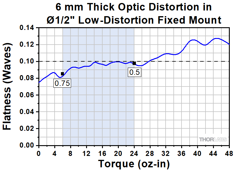
Securing an Optic with a Torque Driver
While we recommend using the method above for securing optics in our low-distortion mounts, the TD24 Torque Driver along with the appropriate spanner bit (see table above) can be used with our Ø1/2" and Ø1" mounts. For the proper torque setting, please refer to the graphs below. Optics can be secured with a force as low as 4 oz-in; for setups requiring long term stability, a force as high as 24 oz-in can be used while keeping the distortion ≤0.10λ.
Note: We do not recommend using a torque wrench for mounting an optic in our Ø2" Polaris low-distortion mounts. The increased diameter of the optic cell makes it difficult to get an accurate reading; this can lead to mounting an optic with too much force, resulting in increased distortion of the optic face, or too little force, leaving the optic loose in the mount.
Optic Distortion
The graphs below show the effects varying amounts of torque or retaining ring reverse turns have on the surface of mirrors mounted in our Polaris low-distortion mounts. The shaded regions illustrate the acceptable range of torque and turns back; the text labels indicate the amount of turns back corresponding to the recommended torque values. Minimal turns back should be used for setups that will be exposed to vibrations, while stationary setups may be able to accommodate more turns back. All flatness measurements are taken with a ZYGO interferometer, which uses a 633 nm beam. Please see the Test Data tab for more information on optic face distortion as a result of torque.
Click to Enlarge
The dashed line indicates 0.10λ for reference. The shaded region represents the recommended torque range. The black dots represent the torque and flatness yielded by using a standard spanner wrench and then loosening the retaining ring the number of turns indicated by the number below the dot. Data for torque values above the shaded region are given for reference and will yield distortion values significantly higher than 0.10λ.
Above 30 oz-in, the retaining ring contacts the optic; in situations where higher torque is desired, two wavesprings may be stacked to achieve the flatness indicated by the red line.

Click to Enlarge
The dashed line indicates 0.10λ for reference. 1.25 turns back from optic contact is recommended for secure mounting with minimal additional distortion caused by the mount. The error bars signify the standard deviation of the test results at every 0.25 turn interval. The spring will start to disengage from the optic at 3.25 turns back.
Several common factors typically lead to beam misalignment in an optical setup. For fixed optic mounts, these include temperature-induced hysteresis of the optic's position. Polaris® fixed mounts are designed specifically to minimize this misalignment factor and thus provide extremely stable performance. Hours of extensive research, multiple design efforts using sophisticated design tools, and months of rigorous testing went into choosing the best components to provide an ideal solution for experiments requiring ultra-stable performance from a fixed optic mount.
Thermal Hysteresis
The temperature in most labs is not constant due to factors such as air conditioning, the number of people in the room, and the operating states of equipment. Thus, it is necessary that all mounts used in an alignment-sensitive optical setup be designed to minimize any thermally induced alignment effects. Thermal effects can be minimized by choosing materials with a low coefficient of thermal expansion (CTE), such as stainless steel. However, even mounts made from a material with a low CTE do not typically return the optic to its initial position when the initial temperature is restored. Polaris fixed optic mounts are heat treated prior to assembly since this process removes internal stresses that can cause a temperature-dependent hysteresis. As a result, the alignment of the optical system will be restored when the temperature of the mirror mount is returned to the initial temperature.
The method by which the mirror is secured in the mount is another important design factor for Polaris mounts. Polaris mounts employ optic mounting designs that reduce optical surface distortion, minimize temperature sensitivity, and limit temperature-dependent hysteresis. Glue-in mounts rely on an adhesive to fix the optic in place. Flexure clamp mounts minimize distortion with three optic contact points and using controlled mounting setscrew torque. Low-distortion mounts employ three front contact points, a wave spring, and retaining ring to further minimize distortion, as described and illustrated in the Low-Distortion Optic Mounts section below.
Vacuum Compatible and Low Outgassing
The Polaris mounts sold on this page are designed to be compatible with cleanroom and vacuum chamber applications. They are chemically cleaned using the Carpenter AAA passivation method to remove sulfur, iron, and contaminants from the surface. After passivation, they are assembled in a clean environment and then double vacuum bagged to eliminate contamination when transported into a cleanroom. When operating at pressures below 10-5 Torr, we highly recommend using an appropriate bake out procedure prior to installing the mount in order to minimize contamination caused by outgassing. Please note that the 8-32 and M4 cap screws included with the Polaris mounts are not rated for pressures below 10-5 Torr.
Cleanroom-Compatible Packaging
Each vacuum-compatible Polaris mount is packaged within two vacuum bag layers after assembly in a clean environment. The vacuum-tight fit minimizes rubbing against the bag, preventing the introduction of bag material shavings that would contaminate the clean mount. In the vacuum-sealing process, moisture-containing air is drawn out of the packaging. This eliminates unwanted reactions on the surface of the mount without the need for desiccant materials.
The vacuum bags protect the mount from contamination by air or dust during transport and storage, and the double-vacuum bag configuration allows for a straightforward and effective cleanroom entry procedure. The outer bag can be removed outside of the cleanroom, allowing the contaminant-free inner bag to be placed into a clean container and transferred into the cleanroom while retaining the benefits of vacuum-bag packaging. Inside the cleanroom, the mount can be removed from the inner bag when ready for use.
Low-Distortion Optic Mounts
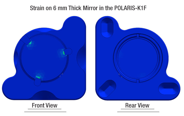
Mounting stresses are responsible for the strain on an optic that results in optic distortion. Minimizing distortion effects is crucial; any distortion to the optic is transmitted to the light that is reflected from it. The POLARIS-B05F, -B1F, and -B2F Low-Distortion Fixed Optics Mounts provide a low-distortion solution for stable mounting without permanently affixing the optic. Each mount uses an indexed wave spring, retaining ring with calibrated adjustment stop, and three retention fingers that contact the front surface of the optic.
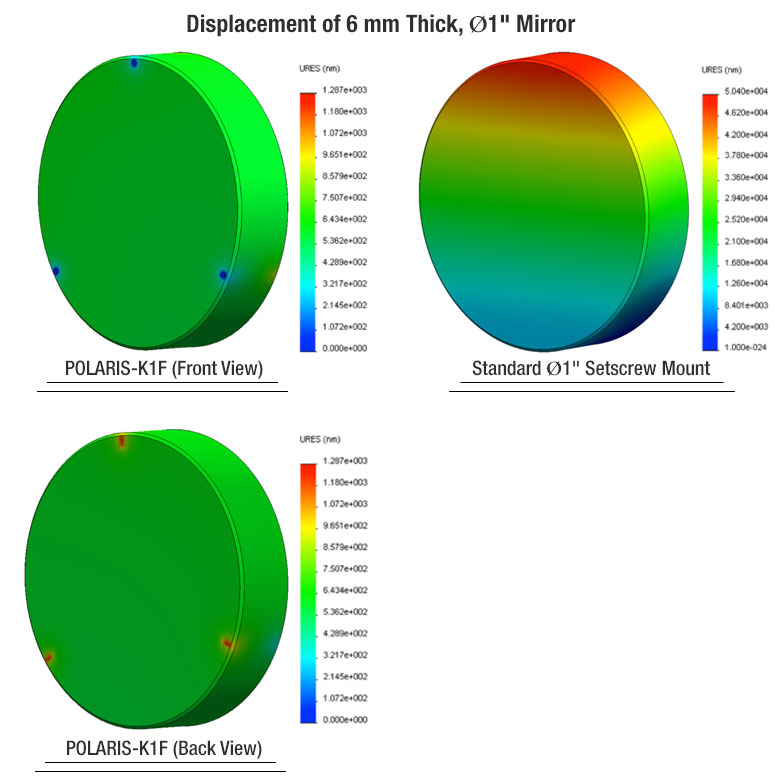
Placing the 3-point mounting forces perpendicular to the face of the optic and indexing them directly opposite each other minimizes bending moments on the optic, thus reducing optic distortion. Typical 360° face mounts and side-located setscrew mounts create bending moments that cause optic distortion as seen in the drawings below. Spring loading the optic allows one to gradually tune the retention force, dampening stresses caused by temperature changes, and it provides a soft means of compensating for variances in manufacturing that can further produce stress on the optic. The finite element analysis results shown below show the displacement, stress, and strain applied to the optic for 20 oz-in of torque applied to the retaining ring of our POLARIS-K1F mount and 10 oz-in of torque applied to the setscrew of the equivalent standard setscrew mount. The POLARIS-B05F, POLARIS-B1F, and and POLARIS-B2F mounts sold below also have similar designs and therefore will show similar performance to the POLARIS-K1F.
Click for Details
Results of finite element analysis comparing the displacement experienced by a Ø1" mirror installed in a POLARIS-K1F mount with 20 oz⋅in of torque applied to the retaining ring (left) to the same optic installed in an equivalent standard setscrew mount with 10 oz⋅in of torque applied to the setscrew (right). Note: the magnitude of the worst distortion of the Polaris mount is less than the smallest distortion on the standard mount, even though the false color map utilizes the same hue.

Click to Enlarge
Polaris Glue-In Fixed Optic Mounts on a Kinematic Platform Mount
Polaris® fixed optic mounts are specifically designed to provide excellent performance under thermal changes and vibrations. Below are some usage tips to ensure that the mount provides optimal performance.
Mounting Options
Due to its relatively low coefficient of thermal expansion, stainless steel was chosen as the material from which to fabricate these Polaris mounts. When mounting a Polaris to a post, we recommend using components fabricated from the same material, such as our Ø1" Posts for Polaris Mirror Mounts and our Polaris Clamping Arm. By choosing components fabricated from the same material as the mount itself, all expansions and contractions will occur at the same rate. In addition, it is best to use the shortest possible post. Alternatively, Polaris mounts can be mounted directly onto a flat surface like a breadboard using a 1/4"-20 to 8-32 thread adapter (Item # AE8E25E) or M6 to M4 thread adapter (Item # AE4M6M), resulting in even better performance. Ensure that the mounting surface is highly flat, polished, and free of debris or scratches.
Polaris Ø1/2" fixed mounts are compact and ideal for space-constrained setups, as shown in the photo to the right.
Polish and Clean the Points of Contact
We highly recommend that the points of contact between the mount and the post, as well as the post and the table, are clean and free of scratches or defects. For best results, we recommend using a polishing stone to clean the table’s surface and a polishing pad for the top and bottom of the post as well as the bottom of the mount.
| Posted Comments: | |
Iain Wilkinson
(posted 2023-10-19 15:26:14.98) Do you have plans to offer Polaris C3G or B3F mounts for 75 mm or 3" outer diameter optics? jdelia
(posted 2023-10-20 08:35:33.0) Thank you for contacting Thorlabs and for providing this feedback! While we do not currently have plans to release either of these products as 3" version, I could certainly forward along your request to our design engineers via our internal suggestion forum for consideration as future catalog products Jack Sparrow
(posted 2023-09-21 16:16:48.19) I want a SolidWorks file of previous version like 2020, and the same as many other mounts. jdelia
(posted 2023-09-21 01:14:26.0) Thank you for contacting Thorlabs. While this is unfortunately not something we can offer, you can download the Step file for the POLARIS-B1S here: https://www.thorlabs.com/_sd.cfm?fileName=TTN111763-E0W.step&partNumber=POLARIS-B1S. Additionally, you can download the Step files for all of our mounts directly on the product and product family pages here on the website. user
(posted 2023-03-30 17:17:06.027) I'd like to build a setup with these holders, but I can't find any SM05 or SM1 version. So I don't see any easy solution to embed small mounted lenses. cdolbashian
(posted 2023-04-10 02:40:46.0) Thank you for reaching out to us with this inquiry! We potentially do have some solutions using our glue-in optic mounts! I have contacted you directly to identify such a solution. Benjamin Stuhl
(posted 2023-02-10 14:08:15.81) It would be very nice if there was a 45deg pitched version of the C1G: the POLARIS-MA45 45deg adapter basically doubles the beam height compared to the C1G, which goes against the point of using the compact C1G in the first place. jdelia
(posted 2023-02-13 01:53:18.0) Thank you for contacting Thorlabs, and for providing this valuable feedback. While this is not something we currently offer, I could certainly pass your request along to our design engineers through our internal suggestion forum. seifahrt
(posted 2018-05-05 14:59:56.56) The screws provided with the Polaris-B1S/M are too long to fix the mount on a metric Polaris mounting post. They reach the bottom of the tapped hole before tightening the mount. Haven't checked the imperial version, but I think I had a similar problem there. Incidentally, the depth of the M4 (8-32) tapped hole in the Polaris mount posts is not specified in the drawings for the posts. llamb
(posted 2018-05-14 09:12:42.0) Thank you for your feedback. The #8-32 and M4 cap screws provided with the POLARIS-B1S have 0.5" and 12 mm long threads respectively. The bottom of the counterbore in the POLARIS-B1S is 0.15" thick where the cap screw sits. Given the counterbore thickness, at most only 0.35" of thread should be sticking out of the bottom of the -B1S. The Ø1" posts for Polaris mirror mounts (our PLS- series) have a #8-32 (M4) thread that is 0.375" deep, so you should not be able to bottom out in the PLS- post threads with the provided cap screws and the -B1S mount. I will reach out to you directly to troubleshoot and see if replacement parts need to be sent out. nicholsm
(posted 2018-03-30 00:42:04.937) I would definitely like to use these options in an optics setup, but is there an option optimized for 2" mirrors? That would be useful as well. llamb
(posted 2018-03-30 10:45:58.0) Hello, thank you for contacting Thorlabs. While we do not currently offer a standard Ø2" option for the Polaris fixed optic mounts, we may be able to offer a special custom product. I will add this new product idea to our internal forum and also reach out to you directly to discuss a quote. |
Thorlabs offers several different general varieties of Polaris mounts, including kinematic side optic retention, SM-threaded, low optic distortion, piezo-actuated, vertical drive, and glue-in optic mounts, a fixed monolithic mirror mount and fixed optic mounts, XY translation mounts, 5-axis kinematic mount, and a kinematic platform mount. Refer to the tables below for our complete line of Polaris mounts, grouped by mount type, optic bore size, and then arranged by optic retention method and adjuster type (or intended application in the case of fixed mounts). We also offer a line of accessories that have been specifically designed for use with our Polaris mounts; these are listed in the table to the lower right. Note that the tables below list Item # suffixes that omit the "POLARIS" prefix for brevity. Click the photos below for details.
| Polaris Mount Optic Retention Methods | |||
|---|---|---|---|
| Side Lock | SM Threaded | Low Distortion | Glue-In |
 |
 |
 |
 |
| Polaris Mount Adjuster Types | |||||
|---|---|---|---|---|---|
| Side Hole | Hex | Adjuster Knobs | Adjuster Lock Nuts |
Piezo Adjusters | Vertical-Drive Adjusters |
 |
 |
 |
 |
 |
 |
| Polaris Kinematic Mounts for Round Optics | ||||
|---|---|---|---|---|
| Optic Retention Method | Side Lock | SM Threaded | Low Distortion | Glue-In |
| Ø1/2" Optics | ||||
| 2 Side Hole Adjusters | - | - | - | -K05C4 -K05G4 |
| 2 Hex Adjusters | -K05S1 | -K05T1 | -K05F1 | - |
| 2 Adjusters with Lock Nuts | -K05S2 | -K05T2 | -K05F2 | - |
| 2 Piezoelectric Adjusters | -K05P2 | - | - | - |
| 2 Vertical Adjusters | -K05VS2 -K05VS2L |
- | - | - |
| 3 Hex Adjusters | -K05 | - | - | - |
| 3 Adjusters with Lock Nuts | - | -K05T6 | -K05F6 | - |
| 3 Adjuster Knobs (Tip/Tilt/Z) & 2 Hex Adjusters (X/Y) |
- | -K05XY | - | - |
| Ø19 mm (3/4") Optics | ||||
| 2 Side Hole Adjusters | -K19S4 | - | -K19F4/M | -K19G4 |
| Ø25 mm Optics | ||||
| 2 Side Hole Adjusters | -K25S4/M | - | -K25F4/M | - |
| Ø1" Optics | ||||
| 2 Side Hole Adjusters | -K1S4 | - | - | -K1C4 -K1G4 |
| 2 Hex Adjusters | -K1E2 -K1-2AH |
-K1T2 | -K1F2 | - |
| 2 Adjuster Knobs | - | -K1T1 | -K1F1 | - |
| 2 Piezoelectric Adjusters | -K1S2P | - | - | - |
| 2 Vertical Adjusters | -K1VS2 -K1VS2L |
- | - | - |
| 3 Side Hole Adjuster | -K1S5 | - | - | - |
| 3 Hex Adjusters | -K1E3 -K1-H |
-K1T3 | - | - |
| 3 Adjuster Knobs | -K1E -K1 |
-K1T | -K1F | - |
| 3 Piezoelectric Adjusters | -K1S3P | - | - | - |
| 3 Adjuster Knobs (Tip/Tilt/Z) & 2 Hex Adjusters (X/Y) |
- | -K1XY | - | - |
| Optic Retention Method | Side Lock | SM Threaded | Low Distortion | Glue-In |
| Ø1.5" Optics | ||||
| 2 Side Hole Adjusters | -K15S4 | - | -K15F4 | - |
| 2 Vertical Adjusters | -K15VS2 -K15VS2L |
- | - | - |
| 3 Adjuster Knobs (Tip/Tilt/Z) & 2 Hex Adjusters (X/Y) |
- | -K15XY | - | - |
| Ø50 mm Optics | ||||
| 2 Side Hole Adjusters | -K50S4/M | - | -K50F4/M | - |
| Ø2" Optics | ||||
| 2 Hex Adjusters | -K2S2 | -K2T2 | -K2F2 | - |
| 2 Adjuster Knobs | -K2S1 | -K2T1 | -K2F1 | - |
| 2 Piezoelectric Adjusters | -K2S2P | - | - | - |
| 2 Vertical Adjusters | -K2VS2 -K2VS2L |
- | - | - |
| 3 Hex Adjusters | -K2S3 | -K2T3 | -K2F3 | - |
| 3 Adjuster Knobs | -K2 | -K2T | -K2F | - |
| Ø3" Optics | ||||
| 2 Side Hole Adjusters | -K3S4 | - | - | - |
| 3 Side Hole Adjusters | -K3S5 | - | - | - |
| Ø4" Optics | ||||
| 2 Side Hole Adjusters | - | - | -K4F4 | - |
| Ø6" Optics | ||||
| 2 Side Hole Adjusters | - | - | -K6F4 | - |
| Polaris XY Translation Mounts for Round Optics | ||
|---|---|---|
| Optic Retention Method | SM Threaded | Representative Photos |
| Ø1/2" Optics | 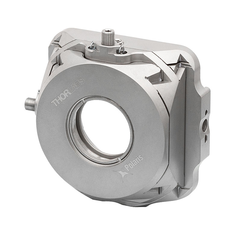 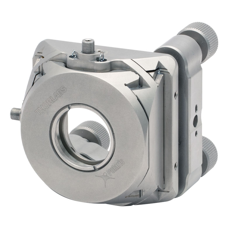 |
|
| 2 Hex Adjusters (X/Y) | -05XY | |
| 3 Adjuster Knobs (Tip/Tilt/Z) & 2 Hex Adjusters (X/Y) |
-K05XY | |
| Ø1" Optics | ||
| 2 Hex Adjusters (X/Y) | -1XY | |
| 3 Adjuster Knobs (Tip/Tilt/Z) & 2 Hex Adjusters (X/Y) |
-K1XY | |
| Ø1.5" Optics | ||
| 2 Hex Adjusters (X/Y) & 3 Adjuster Knobs (Tip/Tilt/Z) |
-K15XY | |
| Polaris Fixed Mounts for Round Optics | ||||||
|---|---|---|---|---|---|---|
| Optic Retention Method | Side Lock | Low Distortion |
Glue-In | Representative Photos |
||
| Ø1/2" Optics |  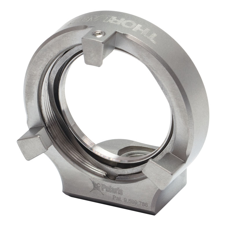  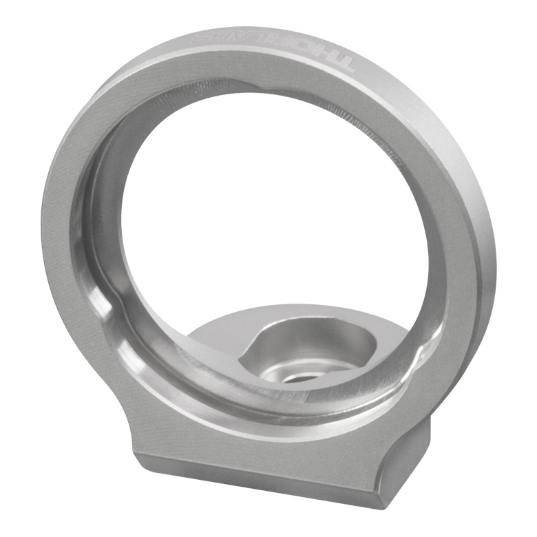 |
|||||
| Optimized for Mirrors | - | -B05F | -C05G | |||
| Optimized for Beamsplitters | -B05S | - | -B05G | |||
| Optimized for Lenses | - | - | -L05G | |||
| Ø19 mm (Ø3/4") Optics | ||||||
| Optimized for Mirrors | -19S50/M | - | - | |||
| Ø1" Optics | ||||||
| Optimized for Mirrors | - | -B1F | -C1G | |||
| Optimized for Beamsplitters | -B1S | - | -B1G | |||
| Optimized for Lenses | - | - | -L1G | |||
| Ø2" Optics | ||||||
| Optimized for Mirrors | - | -B2F | -C2G | |||
| Optimized for Beamsplitters | -B2S | - | - | |||
| Polaris Kinematic 1.8" x 1.8" Platform Mount | ||
|---|---|---|
| Optomech Retention Method | Tapped Holes & Counterbores |
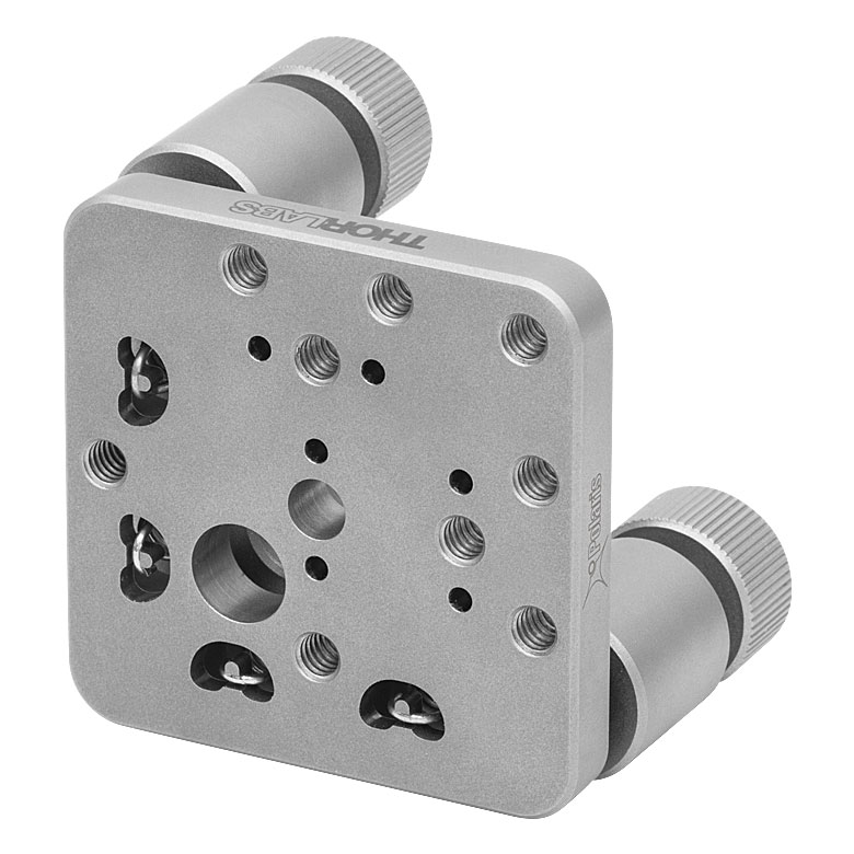 |
| 2 Adjuster Knobs | -K1M4(/M) | |
| Accessories for Polaris Mounts | |
|---|---|
| Description | Representative Photos |
| Ø1" Posts for Polaris Mounts | 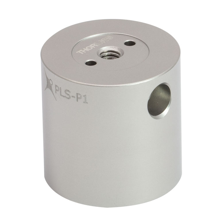 |
| Polaris Non-Bridging Clamping Arms | 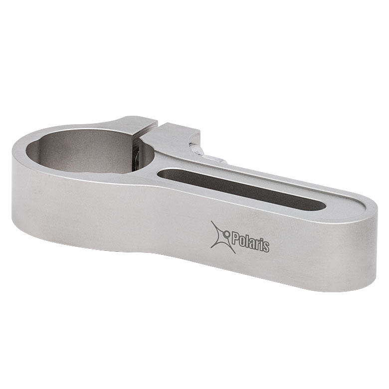 |
| Polaris 45° Mounting Adapter |  |

 Zoom
Zoom
Click to Enlarge
POLARIS-L05G with a Plano-Convex Lens
| Key Specsa | ||
|---|---|---|
| Item # | POLARIS-L05G | POLARIS-L1G |
| Optic Size | Ø1/2"b | Ø1"b |
| Transmissive Clear Aperture | Ø0.39" (Ø10.0 mm) | Ø0.88" (Ø22.3 mm) |
| Beam Deviation | <1 µradc | |
| Mounting | #8 (M4) Counterbored Slot, 0.22" (5.6 mm) Adjustment Range, Two Ø2 mm Alignment Pin Holes |
|
- Lens-Optimized Glue-In Mounts for Ø1/2" or Ø1" Optics
- Counterbored Mounting Slot Allows 0.22" (5.6 mm) Coarse Focusing Adjustment of Lenses
- Mounting Cell with Glue Relief for Minimal Wavefront Distortion
- Three Optic Locating Points for Precise Optic Centering
The POLARIS-L05G and POLARIS-L1G Glue-In Fixed Optic Mounts feature a glue-in optic cell with three optic rim locating points for precise centration of the mounted optic. The adhesive optic mounting method ensures minimal optic surface distortion, providing optimum performance for applications like laser cavity construction. We recommend Norland Optical Adhesive 61 (Item # NOA61, available below) for gluing optics to these mounts. See the Optic Installation tab above for details. The Ø1/2" mount centers the optic at 0.50" above the bottom of the mount, while the Ø1" mount centers the optic at 0.75" above the bottom of the mount.
The mounts feature a #8 (M4) counterbored slot for mounting. The slot allows for a screw to be slightly tightened and then a final focusing adjustment to be made prior to final tightening, ideal for positioning lenses in a setup. In custom mounting configurations, we suggest placing the mount next to a machined flat or removable straight edge to maintain the mount's alignment during the focusing adjustment. For custom mounting configurations where the focusing adjustment is not necessary, two Ø2 mm alignment pin holes are located next to the slot for setting a precise location and mounting angle. We recommend using these mounts with a stainless steel post that also has Ø2 mm alignment pin holes, such as our Ø1" Posts for Polaris Mounts. Standard DIN 7-m6 ground dowel pins are recommended (to view the mechanical drawings, click on the red Docs icons below).

 Zoom
Zoom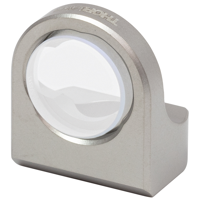
Click to Enlarge
POLARIS-B05G Glue-In Mount with a Plate Beamsplitter

Click to Enlarge
Two cutouts in the optic bore of the Polaris beamsplitter mounts increase the transmissive clear aperture when used at 45° AOI.
| Key Specsa | ||
|---|---|---|
| Item # | POLARIS-B05G | POLARIS-B1G |
| Optic Size | Ø1/2"b | Ø1"b |
| Transmissive Clear Aperture | Ø0.39" (Ø10.0 mm) | Ø0.88" (Ø22.3 mm) |
| Beam Deviation | <1 µradc | |
| Mounting | One #8 (M4) Counterbored Hole & Two Ø2 mm Alignment Pin Holes | |
- Beamsplitter-Optimized Glue-In Mounts for Ø1/2" or Ø1" Optics
- Cut-Outs in the Mounting Plane Maximize Transmissive Clear Aperture
- Mounting Cell with Glue Relief for Minimal Wavefront Distortion
- Three Optic Locating Points for Precise Optic Centering
The POLARIS-B05G and POLARIS-B1G Glue-In Fixed Optic Mounts feature a glue-in optic cell with cut-outs to maximize the transmissive clear aperture, as shown in the images to the right. This feature is especially useful for mounting beamsplitters at a 45° angle of incidence. They may also be used to mount mirrors.
The adhesive optic mounting method ensures minimal optic surface distortion, providing optimum performance for applications like laser cavity construction. We recommend Norland Optical Adhesive 61 (Item # NOA61, available below) for gluing optics to this mount. See the Optic Installation tab above for details. The POLARIS-B05G has two Ø0.25" cutouts aligned horizontally with the center of the mount and centers the optic at 0.50" above the bottom of the mount. The POLARIS-B1G has two Ø0.51" cutouts aligned horizontally with the center of the mount and centers the optic at 0.75" above the bottom of the mount.
The mounts feature a #8 (M4) counterbore for post mounting. For custom mounting configurations, two Ø2 mm alignment pin holes are located next to the counterbore for setting a precise location and mounting angle. We recommend using these mounts with a stainless steel post that also has Ø2 mm alignment pin holes, such as our Ø1" Posts for Polaris Mounts. Standard DIN 7-m6 ground dowel pins are recommended (to view the mechanical drawings, click on the red Docs icons below).

 Zoom
Zoom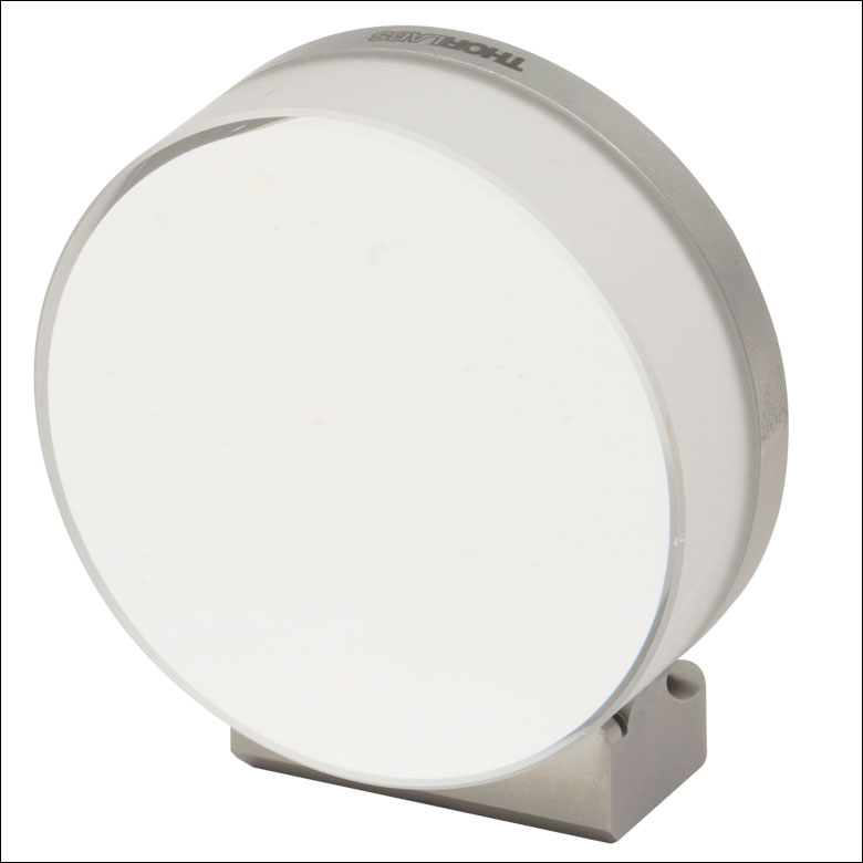
Click to Enlarge
POLARIS-C2G with a Mirror

| Key Specsa | |||
|---|---|---|---|
| Item # | POLARIS-C05G | POLARIS-C1G | POLARIS-C2G |
| Optic Size | Ø1/2"b | Ø1"b | Ø2"b |
| Clear Edge | 180° | 252° | 270° |
| Transmissive Clear Aperture | Ø0.39" (Ø10.0 mm) | Ø0.88" (Ø22.3 mm) | Ø1.80" (Ø45.7 mm) |
| Beam Deviation | <1 µradc | <2 µradd | |
| Mounting | One #8 (M4) Counterbored Hole Two Ø2 mm Alignment Pin Holes |
Three #8 (M4) Counterbored Holes Two Ø2 mm Alignment Pin Holes |
|
- Mirror-Optimized Glue-In Mounts for Ø1/2", Ø1", or Ø2" Optics
- Clear Edge Ideal for Mirrors at Low Angles of Incidence
- Mounting Cell with Glue Relief for Minimal Wavefront Distortion
- Smallest Form Factor of Our Polaris Fixed Optic Mounts
Mirror-Optimized Polaris Glue-In Fixed Mounts feature a 180° (Ø1/2" mount), 252° (Ø1" mount), or 270° (Ø2" mount) clear edge and an optic cell that allows optics to be glued in place. The
The mounts feature #8 (M4) counterbores for post mounting. The Ø1/2" and Ø1" mounts feature one counterbore, while the Ø2" mount features three counterbores for setups requiring extra stability. For custom mounting configurations, two Ø2 mm alignment pin holes are located next to the central counterbore on each mount for setting a precise location and mounting angle. We recommend using these mounts with a stainless steel post that also has Ø2 mm alignment pin holes, such as our Ø1" Posts for Polaris Mounts. Standard DIN 7-m6 ground dowel pins are recommended (to view the mechanical drawings, click on the red Docs icons below).

 Zoom
Zoom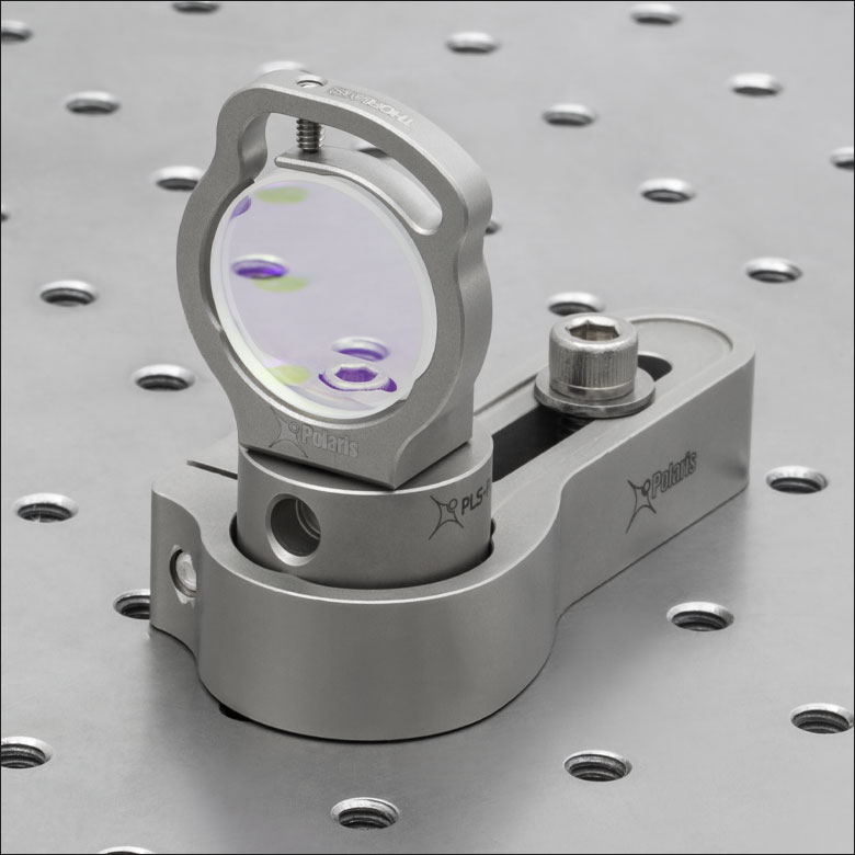
Click to Enlarge
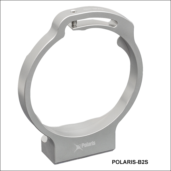
POLARIS-B1S Flexure-Clamp Mount with a Plate Beamsplitter
| Key Specsa | |||
|---|---|---|---|
| Item # | POLARIS-B05S | POLARIS-B1S | POLARIS-B2S |
| Optic Size | Ø1/2" | Ø1" | Ø2" |
| Optic Thickness (Min) | 0.12" (3.0 mm) | 0.15" (3.8 mm) | |
| Transmissive Clear Aperture | Ø0.45" (Ø11.4 mm)b | Ø0.90" (Ø22.9 mm) | Ø1.80" (Ø45.7 mm) |
| Beam Deviation | <1 µradc | ||
| Mounting | One #8 (M4) Counterbored Hole Two Ø2 mm Alignment Pin Holes |
Three #8 (M4) Counterbored Holes Two Ø2 mm Alignment Pin Holes |
|
- Beamsplitter-Optimized Flexure Clamp Mounts for Ø1/2", Ø1", or Ø2" Optics
- Cut-Outs in the Mounting Plane Maximize Transmissive Clear Aperture
- Three Optic Locating Points for Precise Optic Centering
These Beamsplitter-Optimized Flexure Clamp Mounts feature an optic cell with cut-outs to maximize the transmissive clear aperture, as shown in the photos to the right. This feature is especially useful for mounting beamsplitters at a 45° angle of incidence. They may also be used to mount mirrors.
The design features a setscrew and flexure arm combination that provides stable mounting without permanently affixing the optic. When securing the optic in the mount using a 0.05" (1.3 mm) hex key, a torque of 2 - 3 oz-in should be used for the POLARIS-B05S Ø1/2" mount, a torque of 2 - 4 oz-in should be used for the POLARIS-B1S Ø1" mount, and a torque of 6 - 8 oz-in should be used for the POLARIS-B2S Ø2" mount. Use a torque driver to avoid excessive tightening, which leads to optic distortion. The POLARIS-B05S centers the optic 0.50" above the bottom of the mount, the
The mounts feature #8 (M4) counterbores for post mounting. The Ø1/2" and Ø1" mounts feature one counterbore, while the Ø2" mount features three counterbores for setups requiring extra stability. For custom mounting configurations, two Ø2 mm alignment pin holes are located next to the counterbore for setting a precise location and mounting angle. We recommend using these mounts with a stainless steel post that also has Ø2 mm alignment pin holes, such as our Ø1" Posts for Polaris Mounts. Standard DIN 7-m6 ground dowel pins are recommended (to view the mechanical drawings, click on the red Docs icons below). The three #8 (M4) counterbores on the POLARIS-B2S mount are intended for mounting to PLS-T series posts.
The POLARIS-B05S, POLARIS-B1S, and POLARIS-B2S mounts should not be used with Ø12.5 mm, Ø25 mm, or Ø50 mm optics.

 Zoom
Zoom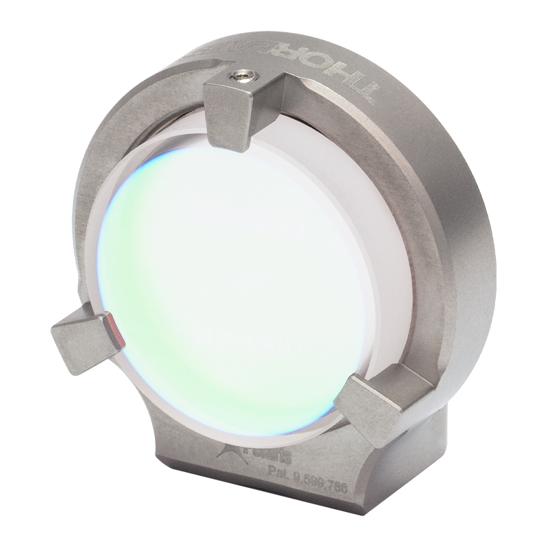
Click to Enlarge
POLARIS-B1F Ø1" Low-Distortion Mount with a Laser Line Mirror

Click to Enlarge
POLARIS-B1F Ø1" Mount
Cutaway Diagram
Click to Enlarge
Wave Spring with Indexing Tab

| Key Specsa | |||
|---|---|---|---|
| Item # | POLARIS-B05F | POLARIS-B1F | POLARIS-B2F |
| Optic Size | Ø1/2" or Ø12.5 mm | Ø1" | Ø2" |
| Optic Thicknessb | 0.09" - 0.28" (2.3 mm - 7 mm) |
0.15" - 0.32" (4 mm - 8.0 mm) |
0.12" - 0.52" (3 mm - 13.3 mm) |
| Transmissive Clear Apertureb |
Ø0.36" (Ø9.1 mm) | Ø0.83" (Ø21.0 mm) | Ø1.73" (Ø43.9 mm) |
| Beam Deviation | <2 µradc | ||
| Mounting | One #8 (M4) Counterbored Hole Two Ø2 mm Alignment Pin Holes |
Three #8 (M4) Counterbored Holes Two Ø2 mm Alignment Pin Holes |
|
| Wave Spring (Included)d | POLARIS-K05WS | POLARIS-K1WS | POLARIS-K2WS |
| Retaining Ring (Included)d | POLARIS-SM05RRS40 | POLARIS-SM1RRS40 | POLARIS-SM2RRS70 |
- Mirror-Optimized Low-Distortion Mounts for Ø1/2", Ø1", or Ø2" Optics
- Wave Spring, Retaining Ring, and Three-Point-Contact Face Plate for Ultra-Low Optic Distortion
Polaris Low-Distortion Optic Mounts (US Patent 9,599,786) provide long-term pointing stability while minimizing optic surface distortion introduced by the mount. Each mount includes one indexed optic retention spring and one retaining ring (see the table below for details) that provides a low-distortion solution for stable mounting without permanently affixing the optic. The indexed optic retention spring makes contact with the optic at three locations, while the retaining ring has a calibrated adjustment stop to assist in providing the correct mounting torque. The Ø1" and Ø2" mounts are also fitted with an additional spring-loaded ball contact for additional stability control; this ball contact is factory set and it should not be adjusted or removed. See the Optic Installation tab above for details and mounting instructions.
These Ø1/2", Ø1", and Ø2" mounts can also be used with POLARIS-SM05RR, POLARIS-SM1RR, and POLARIS-SM2RR retaining rings, respectively, to mount a thicker optic with a larger clear aperture; note that the mount will not provide the same low-distortion performance when used this way.
The mounts feature #8 (M4) counterbores for post mounting. The Ø1/2" and Ø1" mounts feature one counterbore, while the Ø2" mount features three counterbores for setups requiring extra stability. For custom mounting configurations, two Ø2 mm alignment pin holes are located next to the counterbore for setting a precise location and mounting angle. We recommend using these mounts with a stainless steel post that also has Ø2 mm alignment pin holes, such as our Ø1" Posts for Polaris Mounts. Standard DIN 7-m6 ground dowel pins are recommended (to view the mechanical drawings, click on the red Docs icons below). The three #8 (M4) counterbores on the POLARIS-B2F mount are intended for mounting to PLS-T series posts.
The POLARIS-B1F and POLARIS-B2F mounts should not be used with Ø25 mm or Ø50 mm optics, respectively.

 Zoom
ZoomPolaris Recommended Optical Adhesive
NOA61 is recommended for use with our Polaris mounts because of its excellent glass-metal adhesion and low-stress mounting. However, other UV-curing adhesives are available that provide faster curing times or greater flexibility for environments with large temperature fluctuations. Please see our complete presentation for details.
- Low Shrinkage (1.5%) and Low Stress
- Strong Glass-Metal Bond is Ideal for Use with Optics
- Recommended UV Curing Intensity >2 mW/cm2 @ 365 nm
The NOA61 Optical Adhesive is a clear, one-part adhesive that contains no solvents. When exposed to UV light, it gels in seconds and cures fully in minutes to give a tough resilient bond. It has been optimized to adhere optical glass to metal with very little stress, making it ideal for use with our Polaris Glue-In Mounts. To cure these optical adhesives, they must be exposed to UV light. Thorlabs offers a UV curing system that provides an intensity up to 600 mW/cm2.
NOA61 optical adhesive is designed to give the best possible bond to glass surfaces and may be polished after curing. It meets Federal Specification MIL-A-3920 for optical adhesives and is approved for use on all government contracts specifying such adhesives. This adhesive has excellent adhesion to metal, fiberglass and glass-filled plastic.
Shelf Life
These UV-curing adhesives have a shelf life of approximately 8 months. This time frame begins on the date the epoxy was packaged at the manufacturer. Upon receipt by the end user, Thorlabs guarantees that the remaining shelf life will be at least 3 months.
| Item # | Adhesion | Viscosity @ 25 °C | na | Tensile Strength | Shore D Hardness |
Net Weightb | ||
|---|---|---|---|---|---|---|---|---|
| Glass | Metal | Plastic | ||||||
| NOA61 | Excellent | Excellent | Fair | 300 CPS | 1.56 | 3000 psi | 85 | 1 ± 0.07 oz (28 ± 2 g) |

 Zoom
Zoom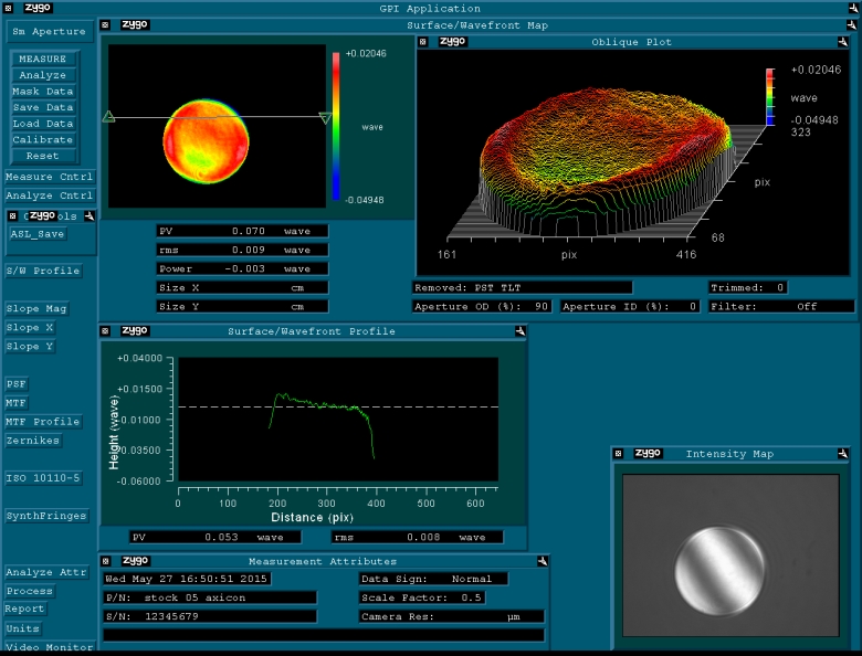
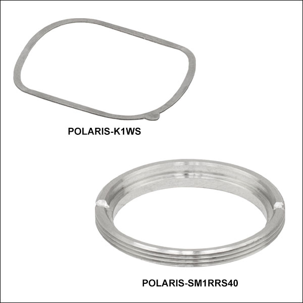
| Item # Suffix | Description | Compatible Fixed Mount |
|---|---|---|
| -K05WS | Ø1/2" Indexed Wave Spring | POLARIS-B05F |
| -K1WS | Ø1" Indexed Wave Spring | POLARIS-B1F |
| -K2WS | Ø2" Indexed Wave Spring | POLARIS-B2F |
| -SM05RRS40 | SM05 Retaining Ring with 0.04" Adj. Stop | POLARIS-B05F |
| -SM1RRS40 | SM1 Retaining Ring with 0.04" Adj. Stop | POLARIS-B1F |
| -SM2RRS70 | SM2 Retaining Ring with 0.07" Adj. Stop | POLARIS-B2F |
- Replacements for Optic Retention Components Included with Low-Distortion Fixed Mounts Sold Above
- Stainless Steel Indexed Wave Spring
- Stainless Steel Retaining Rings with Adjustment Stops
The low-distortion fixed mounts sold above each include one indexed optic retention spring and one retaining ring with an adjustment stop. These items are also available for purchase separately should replacements be required.